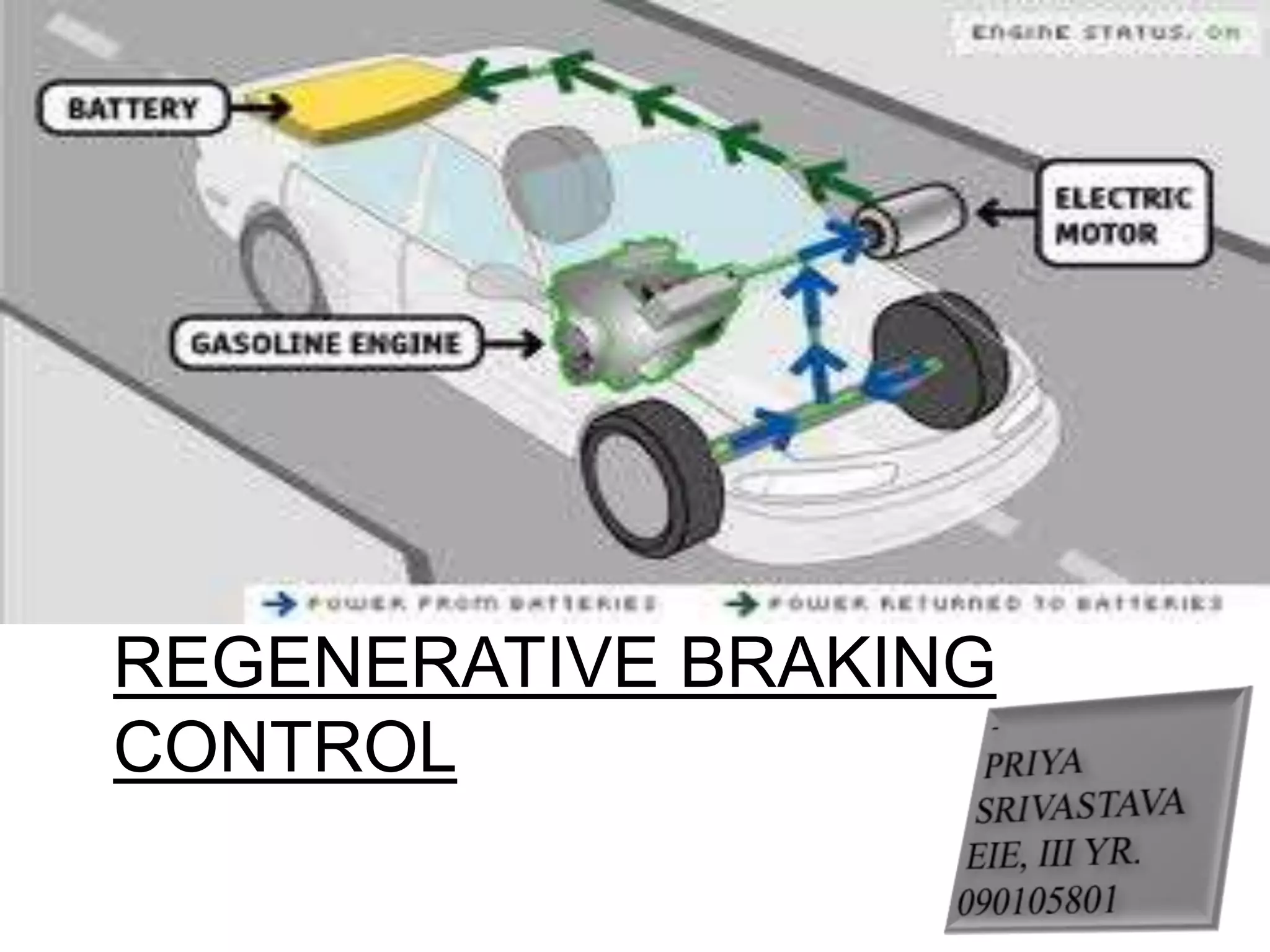
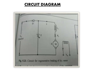
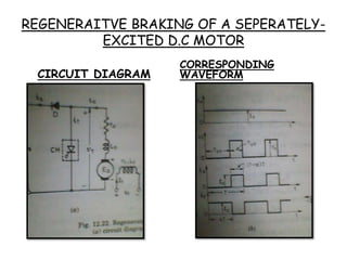
REGENERATIVE BRAKING
CONTROL
DEFINITION
A regenerative brake is
an energy recovery
mechanism which slows
a vehicle or object down
by converting its kinetic
energy into another
form, which can be
either used immediately
or stored until needed.
BRIEF
The mode of operation of a d.c motor changes from motoring action to
regenerative braking when the motor is already rotating with a high inertia load
& it is intended to apply a brake to stop the motor.
Instead of wasting the energy due to inertia of motion by applying either a
mechanical brake or wasting the energy through a resistance, the inertia of the
load is allowed to drive the motor as a generator & spend its inertial energy.
The motor thus will be able to return energy to the source & this will lead to
energy saving.
For regenerative
braking, the
thyristor
connections have to
be changed.
The motor is
separately excited.
This may happen in
situations like when
inertia of a running
train or a vehicle
would be rotating
the motor.
Let the motor
load(may be a fly
wheel) rotating the
motor due to inertia
& the motor is free
for regenerative
braking operation
CIRCUIT DIAGRAM
WORKING
At that time if the thyristor switch, T(or
we could use a power transistor switch)
is made ON, the motor terminals will
virtually get short circuited and a very
heavy current will flow through the
armature & T.
Energy will be stored in the inductance
of the armature circuit. Now, if the
chopper switch is made OFF diode, D
will be turned ON & the energy stored
in the inductance would be returned to
the source of supply.
REGENERAITVE BRAKING OF A SEPERATELY-
EXCITED D.C MOTOR
CIRCUIT DIAGRAM
CORRESPONDING
WAVEFORM
Rheostatic Braking
In rheostat
braking the
kinetic energy
of the motor
load rotates
the motor as a
generator.
The energy, so
generated,
instead of
returning to the
source of supply
is allowed to be
dissipated in a
rheostat.
This resistance Rl
could be a
heater oil in a
car or in an
electric train or
in a Mass Rapid
Transit(MRT)
system.
The heat
generated is
utilized in
heating the
chambers/com
partments of
the vehicle in
winter season.
CIRCUIT DIAGRAM
THANK
YOU!!!..

Pe,ppt

  • 1.
  • 2.
    DEFINITION A regenerative brakeis an energy recovery mechanism which slows a vehicle or object down by converting its kinetic energy into another form, which can be either used immediately or stored until needed.
  • 3.
    BRIEF The mode ofoperation of a d.c motor changes from motoring action to regenerative braking when the motor is already rotating with a high inertia load & it is intended to apply a brake to stop the motor. Instead of wasting the energy due to inertia of motion by applying either a mechanical brake or wasting the energy through a resistance, the inertia of the load is allowed to drive the motor as a generator & spend its inertial energy. The motor thus will be able to return energy to the source & this will lead to energy saving.
  • 4.
    For regenerative braking, the thyristor connectionshave to be changed. The motor is separately excited. This may happen in situations like when inertia of a running train or a vehicle would be rotating the motor. Let the motor load(may be a fly wheel) rotating the motor due to inertia & the motor is free for regenerative braking operation
  • 5.
  • 6.
    WORKING At that timeif the thyristor switch, T(or we could use a power transistor switch) is made ON, the motor terminals will virtually get short circuited and a very heavy current will flow through the armature & T. Energy will be stored in the inductance of the armature circuit. Now, if the chopper switch is made OFF diode, D will be turned ON & the energy stored in the inductance would be returned to the source of supply.
  • 7.
    REGENERAITVE BRAKING OFA SEPERATELY- EXCITED D.C MOTOR CIRCUIT DIAGRAM CORRESPONDING WAVEFORM
  • 8.
    Rheostatic Braking In rheostat brakingthe kinetic energy of the motor load rotates the motor as a generator. The energy, so generated, instead of returning to the source of supply is allowed to be dissipated in a rheostat. This resistance Rl could be a heater oil in a car or in an electric train or in a Mass Rapid Transit(MRT) system. The heat generated is utilized in heating the chambers/com partments of the vehicle in winter season.
  • 9.
  • 10.