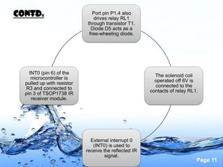
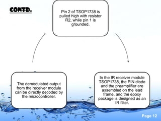
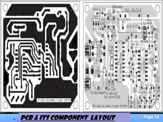
Download to read offline


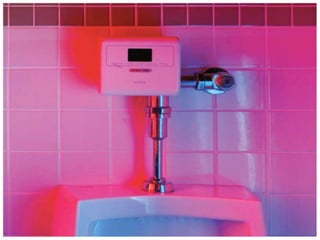
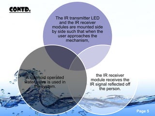
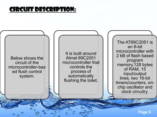
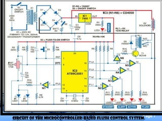
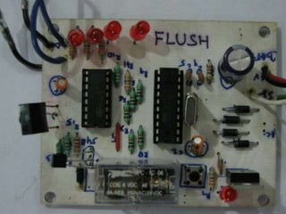

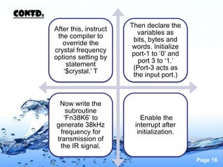
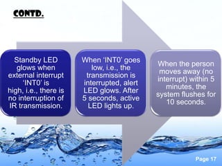


1) This document describes a microcontroller-based automatic flush system that uses an infrared sensor to detect a user's presence and then waits until they depart to flush the toilet. 2) A solenoid is used to actuate the flush from a 6V power supply, which is also powered by a battery backup and controls the sensor circuitry. 3) The system is controlled by a microcontroller and also flushes before the person departs if they are present for more than five minutes.