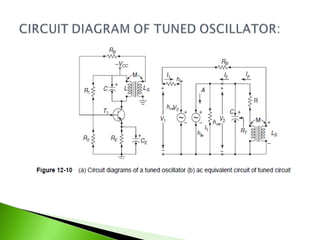
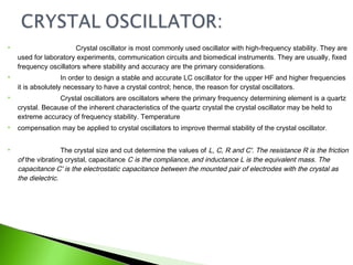
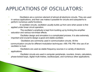
SUBMITTED BY :-
POOJA VISHWAKARMA
SUBMITTED TO :-
Mr. GYAN RAO DHOTE
PHYSICS
Oscillator
 12-1 Introduction
 12-2 Classifications of Oscillators
 12-3 Circuit Analysis of a General Oscillator
 12-4 Conditions for Oscillation: Barkhausen- Criteria
 12-5 Tuned Oscillator
 12-6 Crystal Oscillator
 12-7 Applications of Oscillators
 In this chapter we will explore the working principle of the
oscillator. Generally speaking, the oscillator produces sinusoidal and
other waveforms.
 Beginning with a detailed circuit analysis of the oscillator, we will
proceed to discuss the conditions and frequency of oscillation.
 Following this, the different types of oscillators—Tuned
oscillator, Hartley oscillator, Colpitts oscillator, Clapp
oscillator, Phase-shift oscillator, Crystal oscillator and
Wien-bridge oscillator—will be examined with detailed
mathematical analysis and illustrations.
 The chapter ends with an overview of the applications of the
oscillator.
 An oscillator is an electronic system.
 It comprises active and passive circuit elements and
sinusoidal produces repetitive waveforms at the output without the
application of a direct external input signal to the circuit.
 It converts the dc power from the source to ac power in the
load. A rectifier circuit converts ac to dc power, but an oscillator converts dc
noise signal/power to its ac equivalent.
 The general form of a harmonic oscillator is an electronic
amplifier with the output attached to a narrow-band electronic filter, and the
output of the filter attached to the input of the amplifier.
 In this chapter, the oscillator analysis is done in two methods
—first by a general analysis, considering all other circuits are the special
form of a common generalized circuit and second, using the individual
circuit KVL analysis.
 Oscillators are classified based on the type of the output
waveform.
 If the generated waveform is sinusoidal or close to sinusoidal
(with a certain frequency) then the oscillator is said to be a Sinusoidal
Oscillator.
If the output waveform is non-sinusoidal, which refers to
square/saw-tooth waveforms, the oscillator is said to be a
Relaxation Oscillator.
 An oscillator has a positive feedback with the loop gain
infinite. Feedback-type sinusoidal oscillators can be classified as LC
(inductor-capacitor) and RC (resistor-capacitor) oscillators.
 The classification of various oscillators is shown in Table 12-1.
 This section discusses the general oscillator circuit with a simple
generalized analysis using the transistor, as shown in Fig. 12-2.
 An impedance z1 is connected between the base B and the emitter E, an
impedance z2 is connected between the collector C and emitter E. To apply a
positive feedback z3 is connected between
 the collector and the base terminal.
 All the other different oscillators can be analyzed as a special case of the
generalized analysis of oscillator.
 The above generalized circuit of an oscillator is considered using a simple transistor-equivalent circuit
model. The current voltage expressions are expressed as follows:
 Advantages of Wien-Bridge Oscillator:
 1. The frequency of oscillation can be easily varied just by changing RC
network
 2. High gain due to two-stage amplifier
 3. Stability is high
 Disadvantages of Wien-Bridge Oscillator
 The main disadvantage of the Wien-bridge oscillator is that a high
frequency of oscillation cannot be generated.
 Nyquist criterion states that if this closed curve passes through or
encloses the point (1 + j0), the amplifier becomes unstable and oscillates.
 It is important to note that a positive feedback amplifier will not oscillate
unless the Nyquist criterion is satisfied.
 In the steady state condition the loop gain becomes unity and the
oscillations are sustained, the frequency of oscillations is controlled by the
frequency-determining network of the oscillator.
 The RC and a LC combination circuits are used in oscillators to serve
as the frequency-determining network.
 Let us summarize the key necessities of a feedback oscillator.
1. Amplifier with positive feedback produces a negative resistance in the
system.
2. A frequency-determining network creates oscillations at certain required
frequencies.
3. System non-linearity introduced by the devices contain the amplitude of
oscillation.
 The circuit diagram of a tuned oscillator is shown in Fig. 12-10(a). The emitter by pass
capacitor CE shunts the ac so that RE is omitted from the ac equivalent circuit of Fig. 12-10(b).
 The dc operating point of the transistor is determined by the resistances R1, R2 and
RE, and supply voltage. The transistor gives a phase-shift of 1800
.
Circuit Analysis of Tuned Oscillator:
 Crystal oscillator is most commonly used oscillator with high-frequency stability. They are
used for laboratory experiments, communication circuits and biomedical instruments. They are usually, fixed
frequency oscillators where stability and accuracy are the primary considerations.
 In order to design a stable and accurate LC oscillator for the upper HF and higher frequencies
it is absolutely necessary to have a crystal control; hence, the reason for crystal oscillators.
 Crystal oscillators are oscillators where the primary frequency determining element is a quartz
crystal. Because of the inherent characteristics of the quartz crystal the crystal oscillator may be held to
extreme accuracy of frequency stability. Temperature
 compensation may be applied to crystal oscillators to improve thermal stability of the crystal oscillator.
 The crystal size and cut determine the values of L, C, R and C'. The resistance R is the friction
of the vibrating crystal, capacitance C is the compliance, and inductance L is the equivalent mass. The
capacitance C' is the electrostatic capacitance between the mounted pair of electrodes with the crystal as
the dielectric.
 Oscillators are a common element of almost all electronic circuits. They are used
in various applications, and their use makes it possible for circuits and subsystems to
perform numerous useful functions.
 In oscillator circuits, oscillation usually builds up from zero when power is first
applied under linear circuit operation.
 The oscillator’s amplitude is kept from building up by limiting the amplifier
saturation and various non-linear effects.
 Oscillator design and simulation is a complicated process. It is also extremely
important and crucial to design a good and stable oscillator.
 Oscillators are commonly used in communication circuits. All the
communication circuits for different modulation techniques—AM, FM, PM—the use of an
oscillator is must.
 Oscillators are used as stable frequency sources in a variety of electronic
applications.
 Oscillator circuits are used in computer peripherals, counters, timers, calculators,
phase-locked loops, digital multi-metres, oscilloscopes, and numerous other applications.
 A common oscillator implementation is the voltage-controlled
oscillator (VCO) circuit, where an input tuning voltage is applied to an oscillator circuit
and the tuning voltage adjusted to set the frequency at which the circuit oscillates.
 The VCO is the most widely used oscillator circuit and it produces an
oscillatory output voltage.
 It provides a periodic signal, where the frequency of the periodic signal is
related to the level of an input voltage control signal supplied to the VCO.
 A VCO is simply an oscillator having a frequency output that is proportional
to an applied voltage.
 The centre frequency of a VCO is the frequency of the periodic output
signal formed by the VCO when the input
control voltage is set to a nominal level.
 The cascode crystal oscillator is composed of a Colpitts crystal
oscillator and a base-common buffer amplifier in mobile circuits.
 In the cascode crystal oscillator, a temparature-independent voltage
source biases the buffer amplifier and the bypass capaciter gets eliminated.
 GSM phones, set-top boxes and digital audio broadcasting
equipments use oscillators. and digital audio roadcasting equipment use
oscillators.
 1. Oscillator converts dc to ac.
 2. Oscillator has no input signal.
 3. Oscillator behaviour is opposite to that of a rectifier.
 4. The conditions and frequencies of oscillation are classified as:
OSCILLATOR Chapter+12

OSCILLATOR Chapter+12

  • 1.
    SUBMITTED BY :- POOJAVISHWAKARMA SUBMITTED TO :- Mr. GYAN RAO DHOTE PHYSICS
  • 2.
  • 3.
     12-1 Introduction 12-2 Classifications of Oscillators  12-3 Circuit Analysis of a General Oscillator  12-4 Conditions for Oscillation: Barkhausen- Criteria  12-5 Tuned Oscillator  12-6 Crystal Oscillator  12-7 Applications of Oscillators
  • 4.
     In thischapter we will explore the working principle of the oscillator. Generally speaking, the oscillator produces sinusoidal and other waveforms.  Beginning with a detailed circuit analysis of the oscillator, we will proceed to discuss the conditions and frequency of oscillation.  Following this, the different types of oscillators—Tuned oscillator, Hartley oscillator, Colpitts oscillator, Clapp oscillator, Phase-shift oscillator, Crystal oscillator and Wien-bridge oscillator—will be examined with detailed mathematical analysis and illustrations.  The chapter ends with an overview of the applications of the oscillator.
  • 5.
     An oscillatoris an electronic system.  It comprises active and passive circuit elements and sinusoidal produces repetitive waveforms at the output without the application of a direct external input signal to the circuit.  It converts the dc power from the source to ac power in the load. A rectifier circuit converts ac to dc power, but an oscillator converts dc noise signal/power to its ac equivalent.  The general form of a harmonic oscillator is an electronic amplifier with the output attached to a narrow-band electronic filter, and the output of the filter attached to the input of the amplifier.  In this chapter, the oscillator analysis is done in two methods —first by a general analysis, considering all other circuits are the special form of a common generalized circuit and second, using the individual circuit KVL analysis.
  • 7.
     Oscillators areclassified based on the type of the output waveform.  If the generated waveform is sinusoidal or close to sinusoidal (with a certain frequency) then the oscillator is said to be a Sinusoidal Oscillator. If the output waveform is non-sinusoidal, which refers to square/saw-tooth waveforms, the oscillator is said to be a Relaxation Oscillator.  An oscillator has a positive feedback with the loop gain infinite. Feedback-type sinusoidal oscillators can be classified as LC (inductor-capacitor) and RC (resistor-capacitor) oscillators.
  • 8.
     The classificationof various oscillators is shown in Table 12-1.
  • 9.
     This sectiondiscusses the general oscillator circuit with a simple generalized analysis using the transistor, as shown in Fig. 12-2.  An impedance z1 is connected between the base B and the emitter E, an impedance z2 is connected between the collector C and emitter E. To apply a positive feedback z3 is connected between  the collector and the base terminal.  All the other different oscillators can be analyzed as a special case of the generalized analysis of oscillator.
  • 10.
     The abovegeneralized circuit of an oscillator is considered using a simple transistor-equivalent circuit model. The current voltage expressions are expressed as follows:
  • 31.
     Advantages ofWien-Bridge Oscillator:  1. The frequency of oscillation can be easily varied just by changing RC network  2. High gain due to two-stage amplifier  3. Stability is high  Disadvantages of Wien-Bridge Oscillator  The main disadvantage of the Wien-bridge oscillator is that a high frequency of oscillation cannot be generated.
  • 33.
     Nyquist criterionstates that if this closed curve passes through or encloses the point (1 + j0), the amplifier becomes unstable and oscillates.  It is important to note that a positive feedback amplifier will not oscillate unless the Nyquist criterion is satisfied.  In the steady state condition the loop gain becomes unity and the oscillations are sustained, the frequency of oscillations is controlled by the frequency-determining network of the oscillator.  The RC and a LC combination circuits are used in oscillators to serve as the frequency-determining network.  Let us summarize the key necessities of a feedback oscillator. 1. Amplifier with positive feedback produces a negative resistance in the system. 2. A frequency-determining network creates oscillations at certain required frequencies. 3. System non-linearity introduced by the devices contain the amplitude of oscillation.
  • 36.
     The circuitdiagram of a tuned oscillator is shown in Fig. 12-10(a). The emitter by pass capacitor CE shunts the ac so that RE is omitted from the ac equivalent circuit of Fig. 12-10(b).  The dc operating point of the transistor is determined by the resistances R1, R2 and RE, and supply voltage. The transistor gives a phase-shift of 1800 . Circuit Analysis of Tuned Oscillator:
  • 39.
     Crystal oscillatoris most commonly used oscillator with high-frequency stability. They are used for laboratory experiments, communication circuits and biomedical instruments. They are usually, fixed frequency oscillators where stability and accuracy are the primary considerations.  In order to design a stable and accurate LC oscillator for the upper HF and higher frequencies it is absolutely necessary to have a crystal control; hence, the reason for crystal oscillators.  Crystal oscillators are oscillators where the primary frequency determining element is a quartz crystal. Because of the inherent characteristics of the quartz crystal the crystal oscillator may be held to extreme accuracy of frequency stability. Temperature  compensation may be applied to crystal oscillators to improve thermal stability of the crystal oscillator.  The crystal size and cut determine the values of L, C, R and C'. The resistance R is the friction of the vibrating crystal, capacitance C is the compliance, and inductance L is the equivalent mass. The capacitance C' is the electrostatic capacitance between the mounted pair of electrodes with the crystal as the dielectric.
  • 43.
     Oscillators area common element of almost all electronic circuits. They are used in various applications, and their use makes it possible for circuits and subsystems to perform numerous useful functions.  In oscillator circuits, oscillation usually builds up from zero when power is first applied under linear circuit operation.  The oscillator’s amplitude is kept from building up by limiting the amplifier saturation and various non-linear effects.  Oscillator design and simulation is a complicated process. It is also extremely important and crucial to design a good and stable oscillator.  Oscillators are commonly used in communication circuits. All the communication circuits for different modulation techniques—AM, FM, PM—the use of an oscillator is must.  Oscillators are used as stable frequency sources in a variety of electronic applications.  Oscillator circuits are used in computer peripherals, counters, timers, calculators, phase-locked loops, digital multi-metres, oscilloscopes, and numerous other applications.
  • 44.
     A commonoscillator implementation is the voltage-controlled oscillator (VCO) circuit, where an input tuning voltage is applied to an oscillator circuit and the tuning voltage adjusted to set the frequency at which the circuit oscillates.  The VCO is the most widely used oscillator circuit and it produces an oscillatory output voltage.  It provides a periodic signal, where the frequency of the periodic signal is related to the level of an input voltage control signal supplied to the VCO.  A VCO is simply an oscillator having a frequency output that is proportional to an applied voltage.  The centre frequency of a VCO is the frequency of the periodic output signal formed by the VCO when the input control voltage is set to a nominal level.
  • 45.
     The cascodecrystal oscillator is composed of a Colpitts crystal oscillator and a base-common buffer amplifier in mobile circuits.  In the cascode crystal oscillator, a temparature-independent voltage source biases the buffer amplifier and the bypass capaciter gets eliminated.  GSM phones, set-top boxes and digital audio broadcasting equipments use oscillators. and digital audio roadcasting equipment use oscillators.
  • 46.
     1. Oscillatorconverts dc to ac.  2. Oscillator has no input signal.  3. Oscillator behaviour is opposite to that of a rectifier.  4. The conditions and frequencies of oscillation are classified as: