Download to read offline

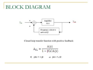
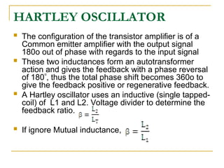
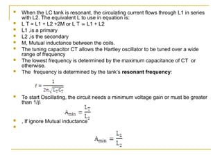
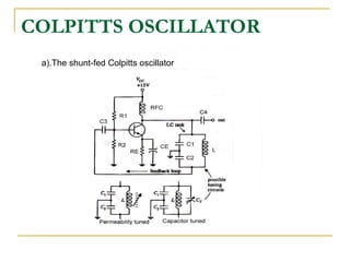
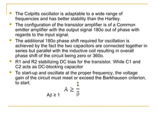

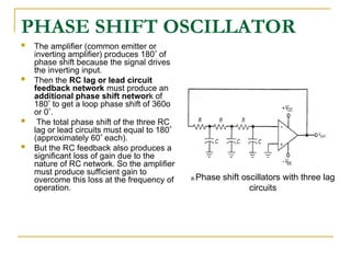


This document discusses the principles and types of electronic oscillators, which convert DC to AC energy at high frequencies using positive feedback for signal oscillation. It details various types of oscillators such as LC, RC, Hartley, Colpitts, and crystal oscillators, including their configurations, operational conditions, and applications in digital devices. The document also explains the Barkhausen criterion for oscillation, emphasizing the importance of phase shift and feedback in maintaining stable oscillations.


![RF Module Design - [Chapter 7] Voltage-Controlled Oscillator](https://cdn.slidesharecdn.com/ss_thumbnails/rfch7-150613070347-lva1-app6892-thumbnail.jpg?width=640&height=640&fit=bounds)