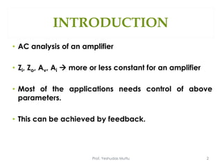
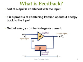
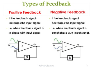
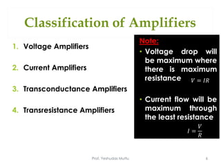
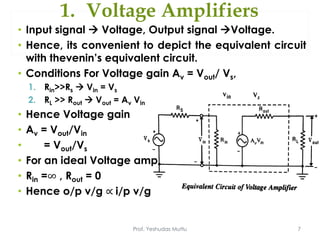
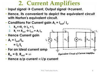
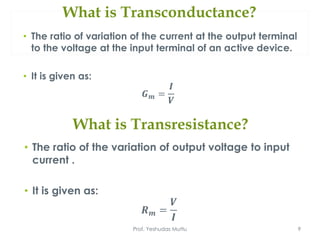
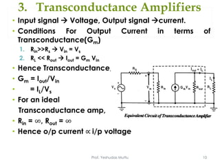
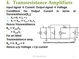
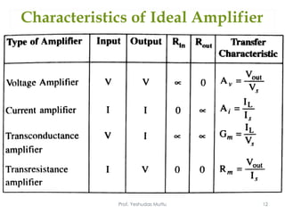
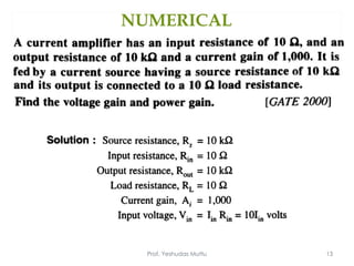
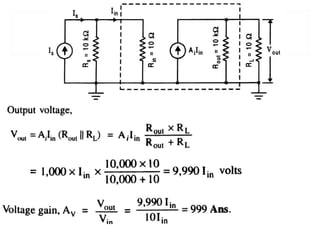
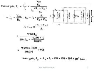
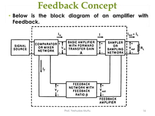
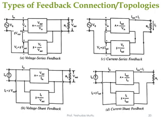
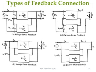
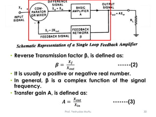
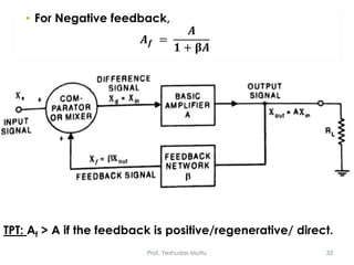
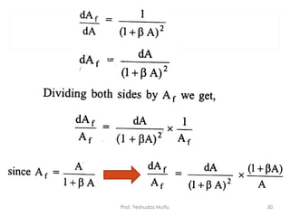
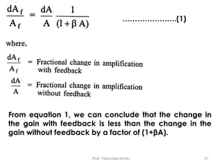
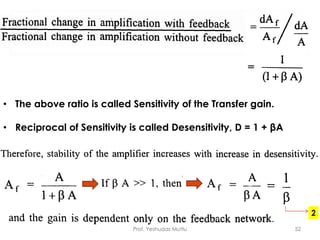
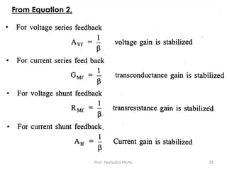
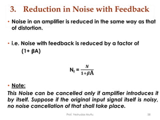
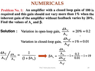
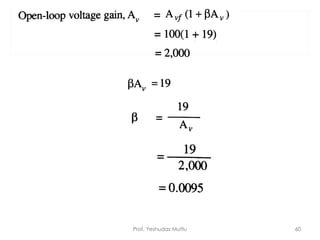
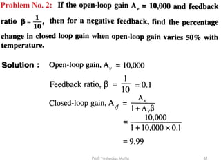
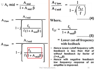
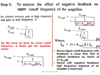
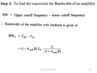
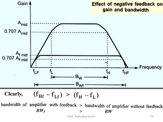
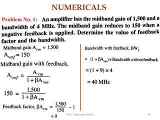
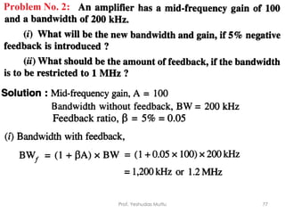
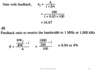
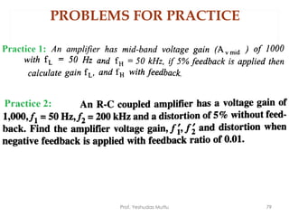
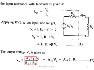
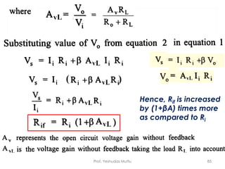
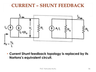
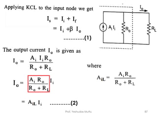
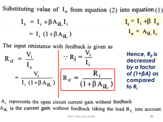
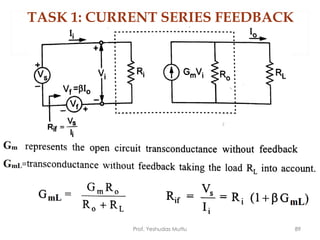
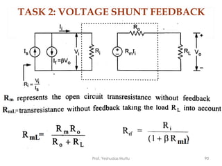
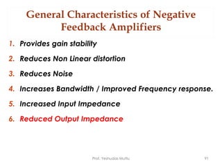
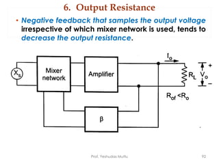
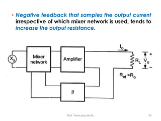
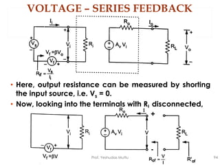
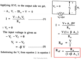
This presentation contains the basics of feedback, types of feedback connection & properties of the negative feedback amplifier. Numericals based on the properties are solved & given for practice.
This presentation contains the basic information you need to know about operational amplifier.
I have tried to cover all the basic info. If anything is left out or you have any suggestions i will appreciate it.
This presentation contains the basics of oscillators, types of oscillators & its mathematical Analysis. Numericals based on each type of oscillator are solved & given for practice.
Field Effect Transistor, JFET, Metal Oxide Semiconductor Field Effect Transistor, Depletion MOSFET, Enhancement MoSFET, Construction, Basic operation, Regions of Operation, Drain Characteristics, Transfer Characteristics, Biasing, Non-Ideal Characteristics of E-MOSFET, DC Analysis, AC equivalent circuit and Parameters, E-MOSFET as an Amplifier, AC analysis, MOSFET as a Switch, MOSFET as a diode, MOSFET as a resistor, High frequency equivalent circuit, Miller Capacitance, Frequency Response, NMOS and CMOS inverter
Oscillators introduction and its types, phase shift oscillators and wein bridge oscillators,difference between phase shift and wein bridge, frequency stability, oscillators principle and conditions, block diagram of oscillators, block diagram of phase shift oscillators
Negative amplifiers and its types Positive feedback and Negative feedbackimtiazalijoono
Negative amplifiers
What is Feedback?
Positive feedback
Negative feedback
Feedback Circuit
Principles of Negative Voltage Feedback In Amplifiers
Gain of Negative Voltage Feedback Amplifier
Advantages of Negative Voltage Feedback
Principles of Negative Current Feedback
Current Gain with Negative Current Feedback
this presentation is based on basic description of inverting and non-inverting amplifiers using op-amps and their medical use, hope it helps students :)
A novel dual-band, dual-polarized antenna-duplexer scheme is intended to use for
WLAN 802.11a and ISM band applications using Substrate Integrated Waveguide (SIW) Technology. The antenna consists of two planar SIW cavities of different dimensions where a smaller sized
diamond-shaped cavity is inserted inside the larger rectangular cavity to share the common aperture
area. The diamond-ring shaped slots are etched in each cavity for radiation. The larger diamondring slot is excited with a microstrip feedline to operate at 5.2 GHz while the smaller slot is excited
with a coaxial probe to operate at 5.8 GHz. The antenna produces linear polarization at 5.2 GHz
(5.1–5.3 GHz) due to the merging of TE110 and TE120 cavity modes while circular polarization
around 5.8 GHz due to orthogonally excited TM100and TM010modes (5.68–5.95 GHz). The slots
are excited in an orthogonal fashion to maintain a better decoupling between the ports (i.e. –23 dB).
The performance of the antenna has been verified in free space as well as in the vicinity of the
human body. The antenna offers the gain of 6.2 dBi /6.6 dBi in free space and 5.8 dBi / 6.4 dBi
on-body at lower-/ higher frequency-bands, respectively. Also, the specific absorption rate (SAR)
is obtained<0.245 W/Kg for 0.5 W input power averaged over 10 mW/g mass of the tissue. The
proposed design is a low-profile, compact single-layered design, which is a suitable option for
off-body communication.
An amplifier is one of the most important applications of transistor. Generally, transistor in CE configuration was used for faithful amplification of signal due to high gain, high input impedance and high power gain. But it has been observed that feedback in an amplifier introduces significant improvement in gain and gives amplified output in required form.
An electronic oscillator is an electronic circuit that produces a periodic, oscillating electronic signal, often a sine wave or a square wave. Oscillators convert direct current (DC) from a power supply to an alternating current (AC) signal. They are widely used in many electronic devices. Common examples of signals generated by oscillators include signals broadcast by radio and television transmitters, clock signals that regulate computers and quartz clocks, and the sounds produced by electronic beepers and video games.
Oscillators designed to produce a high-power AC output from a DC supply are usually called inverters.
There are two main types of electronic oscillator: the linear or harmonic oscillator and the nonlinear or relaxation oscillator.
Automobile Management System Project Report.pdfKamal Acharya
The proposed project is developed to manage the automobile in the automobile dealer company. The main module in this project is login, automobile management, customer management, sales, complaints and reports. The first module is the login. The automobile showroom owner should login to the project for usage. The username and password are verified and if it is correct, next form opens. If the username and password are not correct, it shows the error message.
When a customer search for a automobile, if the automobile is available, they will be taken to a page that shows the details of the automobile including automobile name, automobile ID, quantity, price etc. “Automobile Management System” is useful for maintaining automobiles, customers effectively and hence helps for establishing good relation between customer and automobile organization. It contains various customized modules for effectively maintaining automobiles and stock information accurately and safely.
When the automobile is sold to the customer, stock will be reduced automatically. When a new purchase is made, stock will be increased automatically. While selecting automobiles for sale, the proposed software will automatically check for total number of available stock of that particular item, if the total stock of that particular item is less than 5, software will notify the user to purchase the particular item.
Also when the user tries to sale items which are not in stock, the system will prompt the user that the stock is not enough. Customers of this system can search for a automobile; can purchase a automobile easily by selecting fast. On the other hand the stock of automobiles can be maintained perfectly by the automobile shop manager overcoming the drawbacks of existing system.
Vaccine management system project report documentation..pdfKamal Acharya
The Division of Vaccine and Immunization is facing increasing difficulty monitoring vaccines and other commodities distribution once they have been distributed from the national stores. With the introduction of new vaccines, more challenges have been anticipated with this additions posing serious threat to the already over strained vaccine supply chain system in Kenya.
About
Indigenized remote control interface card suitable for MAFI system CCR equipment. Compatible for IDM8000 CCR. Backplane mounted serial and TCP/Ethernet communication module for CCR remote access. IDM 8000 CCR remote control on serial and TCP protocol.
• Remote control: Parallel or serial interface.
• Compatible with MAFI CCR system.
• Compatible with IDM8000 CCR.
• Compatible with Backplane mount serial communication.
• Compatible with commercial and Defence aviation CCR system.
• Remote control system for accessing CCR and allied system over serial or TCP.
• Indigenized local Support/presence in India.
• Easy in configuration using DIP switches.
Technical Specifications
Indigenized remote control interface card suitable for MAFI system CCR equipment. Compatible for IDM8000 CCR. Backplane mounted serial and TCP/Ethernet communication module for CCR remote access. IDM 8000 CCR remote control on serial and TCP protocol.
Key Features
Indigenized remote control interface card suitable for MAFI system CCR equipment. Compatible for IDM8000 CCR. Backplane mounted serial and TCP/Ethernet communication module for CCR remote access. IDM 8000 CCR remote control on serial and TCP protocol.
• Remote control: Parallel or serial interface
• Compatible with MAFI CCR system
• Copatiable with IDM8000 CCR
• Compatible with Backplane mount serial communication.
• Compatible with commercial and Defence aviation CCR system.
• Remote control system for accessing CCR and allied system over serial or TCP.
• Indigenized local Support/presence in India.
Application
• Remote control: Parallel or serial interface.
• Compatible with MAFI CCR system.
• Compatible with IDM8000 CCR.
• Compatible with Backplane mount serial communication.
• Compatible with commercial and Defence aviation CCR system.
• Remote control system for accessing CCR and allied system over serial or TCP.
• Indigenized local Support/presence in India.
• Easy in configuration using DIP switches.
Overview of the fundamental roles in Hydropower generation and the components involved in wider Electrical Engineering.
This paper presents the design and construction of hydroelectric dams from the hydrologist’s survey of the valley before construction, all aspects and involved disciplines, fluid dynamics, structural engineering, generation and mains frequency regulation to the very transmission of power through the network in the United Kingdom.
Author: Robbie Edward Sayers
Collaborators and co editors: Charlie Sims and Connor Healey.
(C) 2024 Robbie E. Sayers
Hybrid optimization of pumped hydro system and solar- Engr. Abdul-Azeez.pdffxintegritypublishin
Advancements in technology unveil a myriad of electrical and electronic breakthroughs geared towards efficiently harnessing limited resources to meet human energy demands. The optimization of hybrid solar PV panels and pumped hydro energy supply systems plays a pivotal role in utilizing natural resources effectively. This initiative not only benefits humanity but also fosters environmental sustainability. The study investigated the design optimization of these hybrid systems, focusing on understanding solar radiation patterns, identifying geographical influences on solar radiation, formulating a mathematical model for system optimization, and determining the optimal configuration of PV panels and pumped hydro storage. Through a comparative analysis approach and eight weeks of data collection, the study addressed key research questions related to solar radiation patterns and optimal system design. The findings highlighted regions with heightened solar radiation levels, showcasing substantial potential for power generation and emphasizing the system's efficiency. Optimizing system design significantly boosted power generation, promoted renewable energy utilization, and enhanced energy storage capacity. The study underscored the benefits of optimizing hybrid solar PV panels and pumped hydro energy supply systems for sustainable energy usage. Optimizing the design of solar PV panels and pumped hydro energy supply systems as examined across diverse climatic conditions in a developing country, not only enhances power generation but also improves the integration of renewable energy sources and boosts energy storage capacities, particularly beneficial for less economically prosperous regions. Additionally, the study provides valuable insights for advancing energy research in economically viable areas. Recommendations included conducting site-specific assessments, utilizing advanced modeling tools, implementing regular maintenance protocols, and enhancing communication among system components.
NO1 Uk best vashikaran specialist in delhi vashikaran baba near me online vas...Amil Baba Dawood bangali
Contact with Dawood Bhai Just call on +92322-6382012 and we'll help you. We'll solve all your problems within 12 to 24 hours and with 101% guarantee and with astrology systematic. If you want to take any personal or professional advice then also you can call us on +92322-6382012 , ONLINE LOVE PROBLEM & Other all types of Daily Life Problem's.Then CALL or WHATSAPP us on +92322-6382012 and Get all these problems solutions here by Amil Baba DAWOOD BANGALI
#vashikaranspecialist #astrologer #palmistry #amliyaat #taweez #manpasandshadi #horoscope #spiritual #lovelife #lovespell #marriagespell#aamilbabainpakistan #amilbabainkarachi #powerfullblackmagicspell #kalajadumantarspecialist #realamilbaba #AmilbabainPakistan #astrologerincanada #astrologerindubai #lovespellsmaster #kalajaduspecialist #lovespellsthatwork #aamilbabainlahore#blackmagicformarriage #aamilbaba #kalajadu #kalailam #taweez #wazifaexpert #jadumantar #vashikaranspecialist #astrologer #palmistry #amliyaat #taweez #manpasandshadi #horoscope #spiritual #lovelife #lovespell #marriagespell#aamilbabainpakistan #amilbabainkarachi #powerfullblackmagicspell #kalajadumantarspecialist #realamilbaba #AmilbabainPakistan #astrologerincanada #astrologerindubai #lovespellsmaster #kalajaduspecialist #lovespellsthatwork #aamilbabainlahore #blackmagicforlove #blackmagicformarriage #aamilbaba #kalajadu #kalailam #taweez #wazifaexpert #jadumantar #vashikaranspecialist #astrologer #palmistry #amliyaat #taweez #manpasandshadi #horoscope #spiritual #lovelife #lovespell #marriagespell#aamilbabainpakistan #amilbabainkarachi #powerfullblackmagicspell #kalajadumantarspecialist #realamilbaba #AmilbabainPakistan #astrologerincanada #astrologerindubai #lovespellsmaster #kalajaduspecialist #lovespellsthatwork #aamilbabainlahore #Amilbabainuk #amilbabainspain #amilbabaindubai #Amilbabainnorway #amilbabainkrachi #amilbabainlahore #amilbabaingujranwalan #amilbabainislamabad
TECHNICAL TRAINING MANUAL GENERAL FAMILIARIZATION COURSEDuvanRamosGarzon1
AIRCRAFT GENERAL
The Single Aisle is the most advanced family aircraft in service today, with fly-by-wire flight controls.
The A318, A319, A320 and A321 are twin-engine subsonic medium range aircraft.
The family offers a choice of engines
Welcome to WIPAC Monthly the magazine brought to you by the LinkedIn Group Water Industry Process Automation & Control.
In this month's edition, along with this month's industry news to celebrate the 13 years since the group was created we have articles including
A case study of the used of Advanced Process Control at the Wastewater Treatment works at Lleida in Spain
A look back on an article on smart wastewater networks in order to see how the industry has measured up in the interim around the adoption of Digital Transformation in the Water Industry.
CFD Simulation of By-pass Flow in a HRSG module by R&R Consult.pptxR&R Consult
CFD analysis is incredibly effective at solving mysteries and improving the performance of complex systems!
Here's a great example: At a large natural gas-fired power plant, where they use waste heat to generate steam and energy, they were puzzled that their boiler wasn't producing as much steam as expected.
R&R and Tetra Engineering Group Inc. were asked to solve the issue with reduced steam production.
An inspection had shown that a significant amount of hot flue gas was bypassing the boiler tubes, where the heat was supposed to be transferred.
R&R Consult conducted a CFD analysis, which revealed that 6.3% of the flue gas was bypassing the boiler tubes without transferring heat. The analysis also showed that the flue gas was instead being directed along the sides of the boiler and between the modules that were supposed to capture the heat. This was the cause of the reduced performance.
Based on our results, Tetra Engineering installed covering plates to reduce the bypass flow. This improved the boiler's performance and increased electricity production.
It is always satisfying when we can help solve complex challenges like this. Do your systems also need a check-up or optimization? Give us a call!
Work done in cooperation with James Malloy and David Moelling from Tetra Engineering.
More examples of our work https://www.r-r-consult.dk/en/cases-en/
2. INTRODUCTION
• AC analysis of an amplifier
• Zi, Zo, Av, Ai more or less constant for an amplifier
• Most of the applications needs control of above
parameters.
• This can be achieved by feedback.
Prof. Yeshudas Muttu 2
3. What is Feedback?
• Part of output is combined with the input.
• It is a process of combining fraction of output energy
back to the input.
• Output energy can be voltage or current.
Prof. Yeshudas Muttu 3
4. Types of Feedback
Positive Feedback
• If the feedback signal
increases the input signal
• i.e. when feedback signal is
in phase with input signal
Negative Feedback
• If the feedback signal
decreases the input signal
• i.e. when feedback signal is
out of phase w.r.t input signal.
Prof. Yeshudas Muttu 4
5. Types of Feedback
Positive Feedback
• Causes excessive distortion
& instability, hence not used
in amplifiers.
• It has capability of
increasing the power of
original signal, hence used
in oscillators.
Negative Feedback
• Reduces but stabilizes the
amplifier gain & offers many
other advantages.
• This can be compensated by
increasing the number of
stages.
Prof. Yeshudas Muttu 5
6. Classification of Amplifiers
1. Voltage Amplifiers
2. Current Amplifiers
3. Transconductance Amplifiers
4. Transresistance Amplifiers
Prof. Yeshudas Muttu 6
Note:
• Voltage drop will
be maximum where
there is maximum
resistance
• Current flow will be
maximum through
the least resistance.
𝑉 = 𝐼𝑅
𝐼 =
𝑉
𝑅
7. 1. Voltage Amplifiers
Prof. Yeshudas Muttu 7
• Input signal Voltage, Output signal Voltage.
• Hence, its convenient to depict the equivalent circuit
with thevenin’s equivalent circuit.
• Conditions For Voltage gain Av = Vout/ Vs,
1. Rin>>Rs Vin = Vs
2. RL >> Rout Vout = Av Vin
• Hence Voltage gain
• Av = Vout/Vin
• = Vout/Vs
• For an ideal Voltage amp
• Rin =∞ , Rout = 0
• Hence o/p v/g ∝ i/p v/g
8. 2. Current Amplifiers
Prof. Yeshudas Muttu 8
• Input signal Current, Output signal current.
• Hence, its convenient to depict the equivalent circuit
with Norton's equivalent circuit.
• Conditions For Current gain Ai = Iout/ Is,
1. Rin<<Rs Iin = Is
2. RL << Rout Iout = Ai Iin
• Hence Current gain
• Ai = Iout/Iin
• = IL/Is
• For an ideal current amp
• Rin = 0, Rout = ∞
• Hence o/p current ∝ i/p current
9. What is Transconductance?
• The ratio of variation of the current at the output terminal
to the voltage at the input terminal of an active device.
• It is given as:
𝑮 𝒎 =
𝑰
𝑽
Prof. Yeshudas Muttu 9
What is Transresistance?
• The ratio of the variation of output voltage to input
current .
• It is given as:
𝑹 𝒎 =
𝑽
𝑰
10. 3. Transconductance Amplifiers
Prof. Yeshudas Muttu 10
• Input signal Voltage, Output signal current.
• Conditions For Output Current in terms of
Transconductance(Gm)
1. Rin>>Rs Vin = Vs
2. RL << Rout Iout = Gm Vin
• Hence Transconductance,
• Gm = Iout/Vin
• = IL/Vs
• For an ideal
Transconductance amp,
• Rin = ∞, Rout = ∞
• Hence o/p current ∝ i/p voltage
11. 4. Transresistance Amplifiers
Prof. Yeshudas Muttu 11
• Input signal Current, Output signal Voltage.
• Conditions For Output Current in terms of
Transresistance(Rm)
1. Rin<<Rs Iin = Is
2. RL >> Rout Vout = Rm Iin
• Hence Transresistance,
• Rm = Vout/Iin
• = Vout/Is
• For an ideal
Transresistance amp,
• Rin = 𝟎, Rout = 𝟎
• Hence o/p Voltage ∝ i/p current
17. Prof. Yeshudas Muttu 17
Signal Source
• It can be either a Voltage source, Vs in series with a
resistor Rs or
• A Current source Is, in parallel with Rs
Feedback Network
• It is a two port network which may be formed with R, L,
C (most often R).
• Its function is to return the part of output energy(V or I)
to the input of the amplifier.
Explanation of each block
18. Explanation of each block
Voltage/Node
Sampling Network
Current/Loop
Sampling Network
Prof. Yeshudas Muttu 18
Sampling Network
It can be divided into two types:
• Output signal is sampled by
connecting feedback
network in shunt across the
output.
• Output signal is sampled by
connecting feedback
network in series across the
output.
19. Prof. Yeshudas Muttu 19
Comparator/Mixer Network
• It can be divided into two types: Series Mixer & Shunt
Mixer.
• Differential amplifier (Dual i/p, single output) provides
Output proportional to difference i/p signal is used as
a mixer.
Explanation of each block
21. Explanation for Feedback Connections
• The four types are:
1. Voltage Series Feedback
2. Voltage Shunt Feedback
3. Current Series Feedback
4. Current Shunt Feedback
• Voltage refers to Output voltage is fed to the
feedback network. It is taken in parallel.
• Current refers to Output current is fed to the feedback
network. It is measured in series.
• Series refers to connecting the feedback signal in
series with input signal.
• Shunt refers to connecting the feedback signal in
parallel with an input current source.
Prof. Yeshudas Muttu 21
22. Explanation for Feedback Connections
Series Feedback Connection
• It opposes the applied
voltage causing input
current to fall that makes
Zi to increase.
Shunt Feedback Connection
• Current drawn from the
signal source is increased
by amount = If, hence Zi
falls.
Prof. Yeshudas Muttu 22
Voltage Feedback Connection
• Reduces o/p impedance
Current Feedback Connection
• Increases o/p impedance
In cascaded amplifiers, mostly high Zi & low Zo are desired.
This property is provided by Voltage series feedback, hence
they are commonly used.
23. Prof. Yeshudas Muttu
23
Series Feedback Connection Shunt Feedback Connection
Rin = 0,
Rout = ∞
Rin = ∞,
Rout = ∞
Rin = 𝟎,
Rout = 𝟎
Rin =∞ ,
Rout = 0
Current
Shunt
Feedback
Voltage
Series
Feedback
Voltage
Shunt
Feedback
Current
Series
Feedback
VFC
VFC
CFC
CFC
25. Parameters of Amplifier without Feedback
• Transfer gain of basic amplifier without feedback = A
(Output/ Input of basic amplifier).
1. Transfer ratio or Gain, Av = Vout/Vin
2. Current Gain, Ai = Iout/Iin
3. Transconductance, Gm = Iout/Vin
4. Transresistance, Rm = Vout/Iin
Prof. Yeshudas Muttu 25
26. Parameters of Amplifier with Feedback
• Transfer gain of the amplifier with feedback = Af
(Output/ Input of the amplifier).
1. Transfer ratio or Gain with feedback, Avf = Vout/Vs
2. Current Gain with feedback, Aif = Iout/Is
3. Transconductance with feedback, Gmf = Iout/Vs
4. Transresistance with feedback, Rmf = Vout/Is
Prof. Yeshudas Muttu 26
27. To derive relation between A & Af
• Above diagram is generalized feedback amplifier.
• The basic amplifier may be an ideal voltage,
Transresistance, Transconductance or current
amplifier.
• Rs is considered to be part of the amplifier.
Prof. Yeshudas Muttu 27
28. • Transfer gain A includes effect of Loading from
feedback network β, as well as load resistance RL.
• The input signal Xs, the output signal Xout, the
feedback signal Xf & the difference signal Xd, each
represents either voltage or a current.
Prof. Yeshudas Muttu 28
29. • From figure, mixing network’s output is the sum of the
inputs considering the sign indicated at each input.
• Hence Difference signal can be given as:
Xd = Xs – Xf = Xin
Xd is also known as error/comparison signal.
• Hence, Xs = 𝑿𝒊𝒏 + 𝑿 𝒇 -----(1)
Prof. Yeshudas Muttu 29
30. • Reverse Transmission factor β, is defined as:
𝜷 =
𝑿 𝒇
𝑿 𝒐𝒖𝒕
------(2)
• It is usually a positive or negative real number.
• In general, β is a complex function of the signal
frequency.
• Transfer gain A, is defined as:
𝑨 =
𝑿 𝒐𝒖𝒕
𝑿 𝒊𝒏
-------(3)
Prof. Yeshudas Muttu 30
31. • The expression for the transfer gain with feedback
can be given as:
𝑨 𝒇 =
𝑿 𝒐𝒖𝒕
𝑿 𝒔
-------(4)
• Hence, from equations 1 & 4,
𝑨 𝒇 =
𝑿 𝒐𝒖𝒕
𝑿𝒊𝒏 + 𝑿 𝒇
=
𝑿 𝒐𝒖𝒕
𝑿 𝒊𝒏(𝟏+
𝑿 𝒇
𝑿 𝒊𝒏
)
=
𝑿 𝒐𝒖𝒕
𝑿 𝒊𝒏
𝟏+
𝑿 𝒇
𝑿 𝒊𝒏
×
𝑿 𝒐𝒖𝒕
𝑿 𝒐𝒖𝒕
Prof. Yeshudas Muttu 31
32. 𝑨 𝒇 =
𝑿 𝒐𝒖𝒕
𝑿 𝒊𝒏
𝟏+
𝑿 𝒇
𝑿 𝒊𝒏
×
𝑿 𝒐𝒖𝒕
𝑿 𝒐𝒖𝒕
=
𝑿 𝒐𝒖𝒕
𝑿 𝒊𝒏
𝟏+
𝑿 𝒇
𝑿 𝒐𝒖𝒕
×
𝑿 𝒐𝒖𝒕
𝑿 𝒊𝒏
• From equations 2 & 3,
𝑨 𝒇 =
𝑨
𝟏 + 𝛃𝑨
• Af < A if the feedback is negative/degenerative/
Inverse.
Prof. Yeshudas Muttu 32
33. • For Negative feedback,
𝑨 𝒇 =
𝑨
𝟏 + 𝛃𝑨
• For Positive feedback,
Prof. Yeshudas Muttu 33
TPT: Af > A if the feedback is positive/regenerative/ direct.
35. Prof. Yeshudas Muttu 35
𝑨 𝒇 =
𝑨
𝟏 − 𝛃𝑨
𝑨 𝒇 =
𝑿 𝒐𝒖𝒕
𝑿 𝒊𝒏
𝟏−
𝑿 𝒇
𝑿 𝒊𝒏
×
𝑿 𝒐𝒖𝒕
𝑿 𝒐𝒖𝒕
=
𝑿 𝒐𝒖𝒕
𝑿𝒊𝒏
𝟏 −
𝑿 𝒇
𝑿 𝒐𝒖𝒕
×
𝑿 𝒐𝒖𝒕
𝑿𝒊𝒏
Hence, For Positive feedback,
𝑨 𝒇 =
𝑨
𝟏 − 𝛃𝑨
Af > A if the feedback is positive/regenerative/ direct.
36. Prof. Yeshudas Muttu
36
Series Feedback Connection Shunt Feedback Connection
Rin = 0,
Rout = ∞
Rin = ∞,
Rout = ∞
Rin = 𝟎,
Rout = 𝟎
Rin =∞ ,
Rout = 0
Current
Shunt
Feedback
Voltage
Series
Feedback
Voltage
Shunt
Feedback
Current
Series
Feedback
VFC
VFC
CFC
CFC
38. • For Negative feedback,
𝑨 𝒇 =
𝑨
𝟏 + 𝛃𝑨
• For Positive feedback,
𝑨 𝒇 =
𝑨
𝟏 − 𝛃𝑨
Prof. Yeshudas Muttu 38
39. LOOP GAIN/RETURN RATIO
• Difference signal Xd is multiplied with basic amplifier
gain A which is later multiplied with feedback gain β,
that is later multiplied with ‘ – 1’ that results in:
Xd x A x β x (– 1) = –βA Xd
• Where (–βA) is the Loop gain/ Return ratio
• Return difference, D = 1 – (–βA) = 1 + βA
• Amount of feedback introduced in the amplifier is
expressed in decibels.
N = dB of feedback = 20 log10
𝑨 𝒇
𝑨
= 20 log10
𝑨
𝟏+𝛃𝑨
𝑨
N = 20 log10
𝟏
𝟏+𝛃𝑨
Prof. Yeshudas Muttu 39
Where,
N will be
negative
number for
Negative
feedback
40. • Generally, A & β are phasor quantities. i.e. they
have magnitude & phase.
• Every amplifier stage introduces some phase shift.
Eg: Common Emitter amplifier o/p produces 180o
phase shift.
• For 3 – stage amplifier, total phase shift will be:
180 x 3 = 5400
• β usually has phase value of 00 or 1800. i.e. either in
phase with the i/p or in phase opposition to it.
• Hence, (1 – βA) is a complex quantity.
Prof. Yeshudas Muttu 40
48. General Characteristics of Negative
Feedback Amplifiers
1. Provides gain stability
2. Reduces Non Linear distortion
3. Reduces Noise
4. Increases Bandwidth / Improved Frequency response.
5. Increased Input Impedance
6. Reduced Output Impedance
Prof. Yeshudas Muttu 48
49. 1. Stabilization of Gain with Negative Feedback
OR
Desensitivity of Gain
• The transfer gain of the amplifier is not constant as it
depends on the factors such as Operating point,
temperature, etc.
• This lack of stability in amplifiers can be reduced by
introducing negative feedback.
Differentiating with respect to A, (using u/v rule)
Prof. Yeshudas Muttu 49
U
V
51. Prof. Yeshudas Muttu 51
………………….(1)
From equation 1, we can conclude that the change in
the gain with feedback is less than the change in the
gain without feedback by a factor of (1+βA).
52. Prof. Yeshudas Muttu 52
• The above ratio is called Sensitivity of the Transfer gain.
• Reciprocal of Sensitivity is called Desensitivity, D = 1 + βA
54. 2. a) Reduction in Frequency Distortion
• For negative feedback, 𝑨 𝒇 =
𝑨
𝟏+𝛃𝑨
• If 𝛃𝑨>>1, 𝑨f = 𝑨/ 𝛃𝑨 = 1/ 𝛃
• Hence, Gain here, doesn't depend on A, but
depends on 𝛃.
• If feedback network is purely resistive, the overall
gain will be frequency independent. (even though
A is frequency dependent as its eliminated from the
equation)
• Practically, frequency distortion that arises due to
variations in amplifier gain with frequency, is
reduced considerably due to negative feedback.
Prof. Yeshudas Muttu 54
55. 2. b)Reduction in Non-linear Distortion with Feedback
• Consider an amplifier with open loop gain ‘A’ &
closed loop gain ‘Af’ with negative feedback.
• Let this amplifier produce a distortion ‘D’ without
any feedback.
• Let this amplifier produce a distortion ‘Df’ with
feedback.
Prof. Yeshudas Muttu 55
56. Prof. Yeshudas Muttu 56
• With feedback, a part of distortion 𝛃𝐃𝐟 is fed back & is
amplified to get A𝛃𝐃𝐟
• Hence net distortion, Df = D - A𝛃𝐃𝐟 (since –ve feedback
is in phase opposition)
57. D = Df + A𝛃𝐃𝐟
= Df (1+𝛃A)
Hence, Df =
𝑫
𝟏+𝛃A
Therefore, Distortion with feedback is reduced by a
factor of (1+ 𝛃A)
• Note:
This distortion can be cancelled only if amplifier
introduces it by itself.
Suppose if the original input signal itself is distorted,
no distortion cancellation of that shall take place.
Prof. Yeshudas Muttu 57
58. 3. Reduction in Noise with Feedback
• Noise in an amplifier is reduced in the same way as that
of distortion.
• i.e. Noise with feedback is reduced by a factor of
(1+ 𝛃A)
Nf =
𝑵
𝟏+𝜷A
• Note:
This Noise can be cancelled only if amplifier introduces it
by itself. Suppose if the original input signal itself is noisy,
no noise cancellation of that shall take place.
Prof. Yeshudas Muttu 58
66. General Characteristics of Negative
Feedback Amplifiers
1. Provides gain stability
2. Reduces Non Linear distortion
3. Reduces Noise
4. Increases Bandwidth / Improved Frequency response.
5. Increased Input Impedance
6. Reduced Output Impedance
Prof. Yeshudas Muttu 67
67. 4. Frequency Response & Bandwidth
Prof. Yeshudas Muttu 68
• Frequency Response is a variation in the amplitude
level of its output signal when the frequency is changed.
71. Prof. Yeshudas Muttu 72
…………(4)
…………(5)
• Hence Lower cutoff frequency with
feedback is less than that of
without feedback by factor of
(1+Amidβ).
• Hence with negative feedback
low frequency response of an
amplifier is improved.
72. Prof. Yeshudas Muttu 73
Do the same as done for Lower cutoff
frequency & finally get the equation
below
…………(6)
…………(7)
• Hence Upper cutoff frequency with
feedback is more than that of
without feedback by factor of
(1+Amidβ).
• Hence with negative feedback
high frequency response of an
amplifier is improved.
79. General Characteristics of Negative
Feedback Amplifiers
1. Provides gain stability
2. Reduces Non Linear distortion
3. Reduces Noise
4. Increases Bandwidth / Improved Frequency response.
5. Increased Input Impedance
6. Reduced Output Impedance
Prof. Yeshudas Muttu 80
80. 5. Input Resistance
Prof. Yeshudas Muttu 81
• If the feedback signal is added to the input in series
with the applied voltage irrespective of which
sampling is used, it increases the input resistance.
• Since feedback Vf opposes Vs, the input current Ii is
less than what it would have been if Vf was absent.
Hence, Input
resistance with
feedback,
is greater than
the input
resistance (Ri)
without
feedback.
81. Prof. Yeshudas Muttu 82
• If the feedback signal is added to the input in shunt
with the applied voltage irrespective of which
sampling is used, it decreases the input resistance.
• Since Is = Ii + If, current Is drawn from the source is
increased, than what it would have been if If was
absent
Hence, Input
resistance with
feedback,
is less than the
input resistance
(Ri) without
feedback for this
circuit.
82. VOLTAGE – SERIES FEEDBACK
• Voltage series feedback topology is replaced by its
Thevenin’s equivalent circuit.
Prof. Yeshudas Muttu 83
90. General Characteristics of Negative
Feedback Amplifiers
1. Provides gain stability
2. Reduces Non Linear distortion
3. Reduces Noise
4. Increases Bandwidth / Improved Frequency response.
5. Increased Input Impedance
6. Reduced Output Impedance
Prof. Yeshudas Muttu 91
91. 6. Output Resistance
Prof. Yeshudas Muttu 92
• Negative feedback that samples the output voltage
irrespective of which mixer network is used, tends to
decrease the output resistance.
92. Prof. Yeshudas Muttu 93
• Negative feedback that samples the output current
irrespective of which mixer network is used, tends to
increase the output resistance.
93. VOLTAGE – SERIES FEEDBACK
• Here, output resistance can be measured by shorting
the input source, i.e. Vs = 0.
• Now, looking into the terminals with RL disconnected,
Prof. Yeshudas Muttu 94
+
-
96. CURRENT – SHUNT FEEDBACK
• Here, output resistance can be measured by Open
circuiting the input source. i.e. Is = 0.
• Now, looking into the terminals with RL disconnected,
97Prof. Yeshudas Muttu