Downloaded 1,799 times
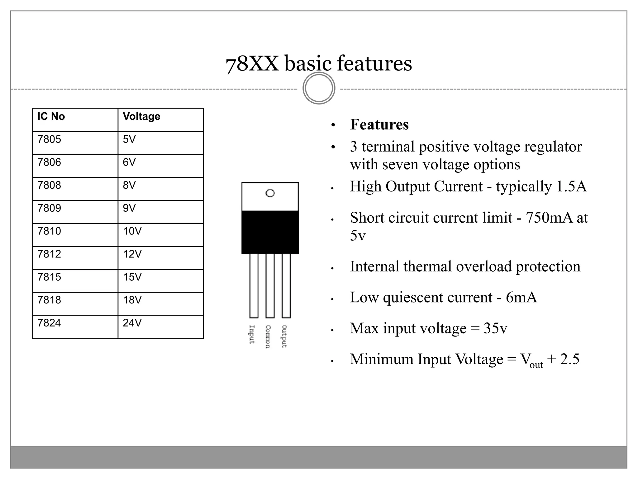
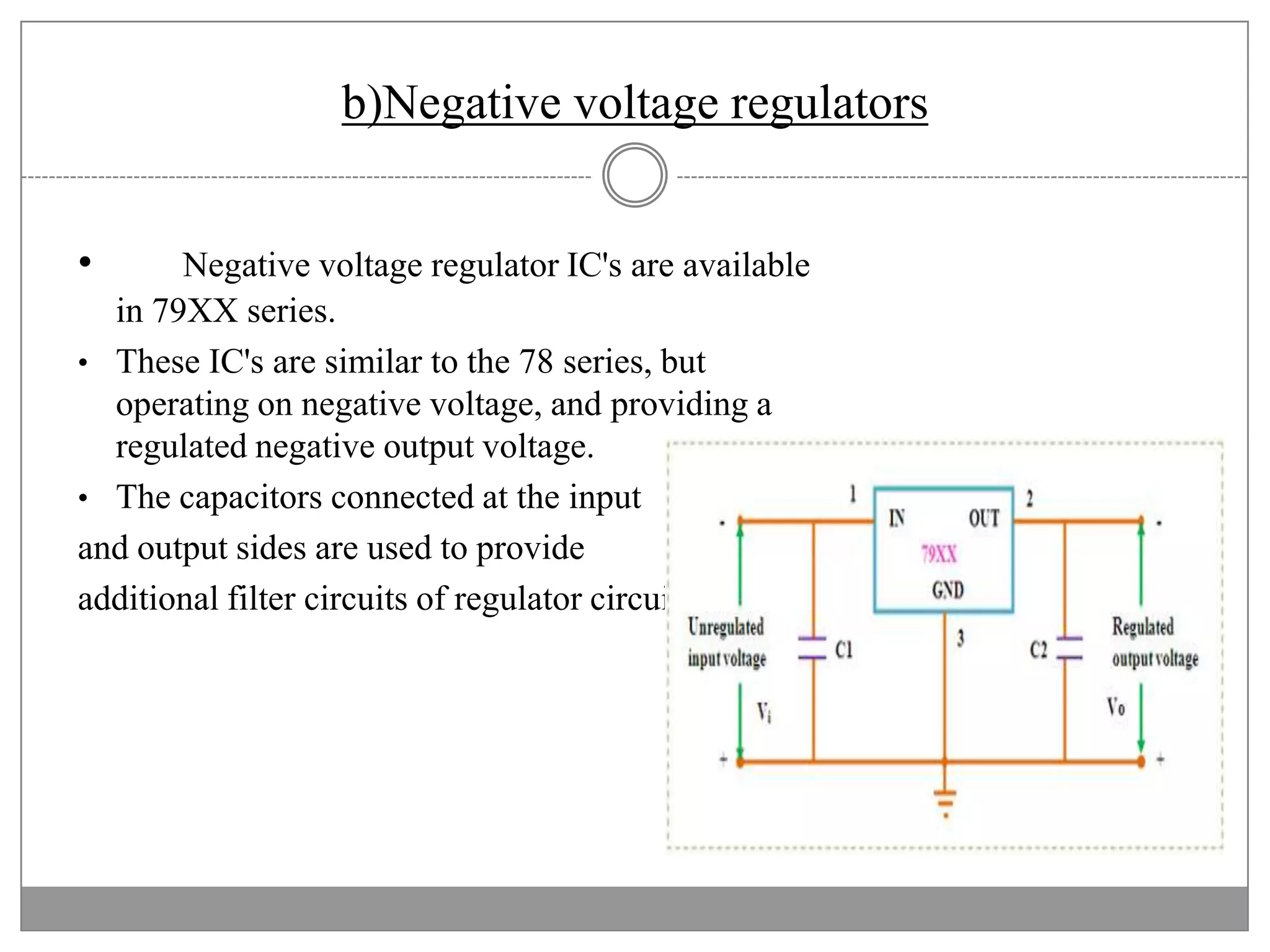
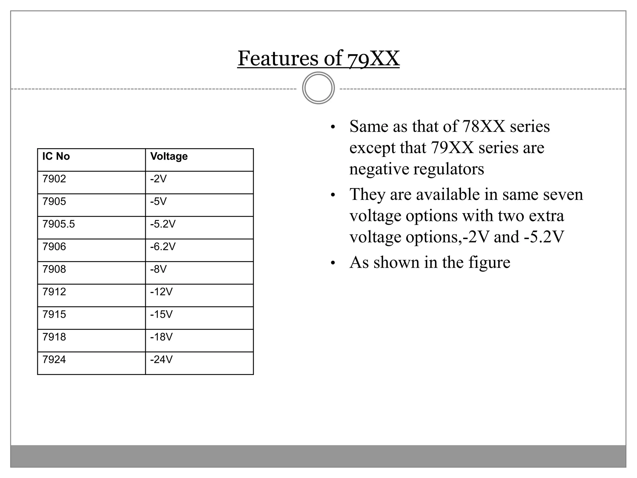
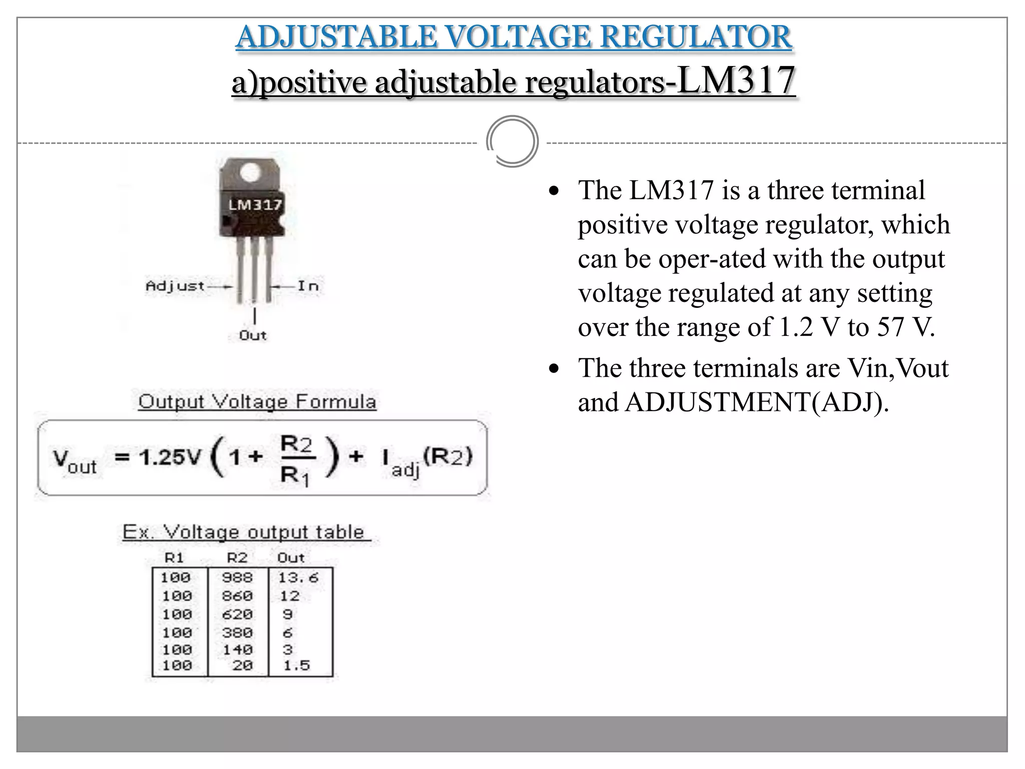
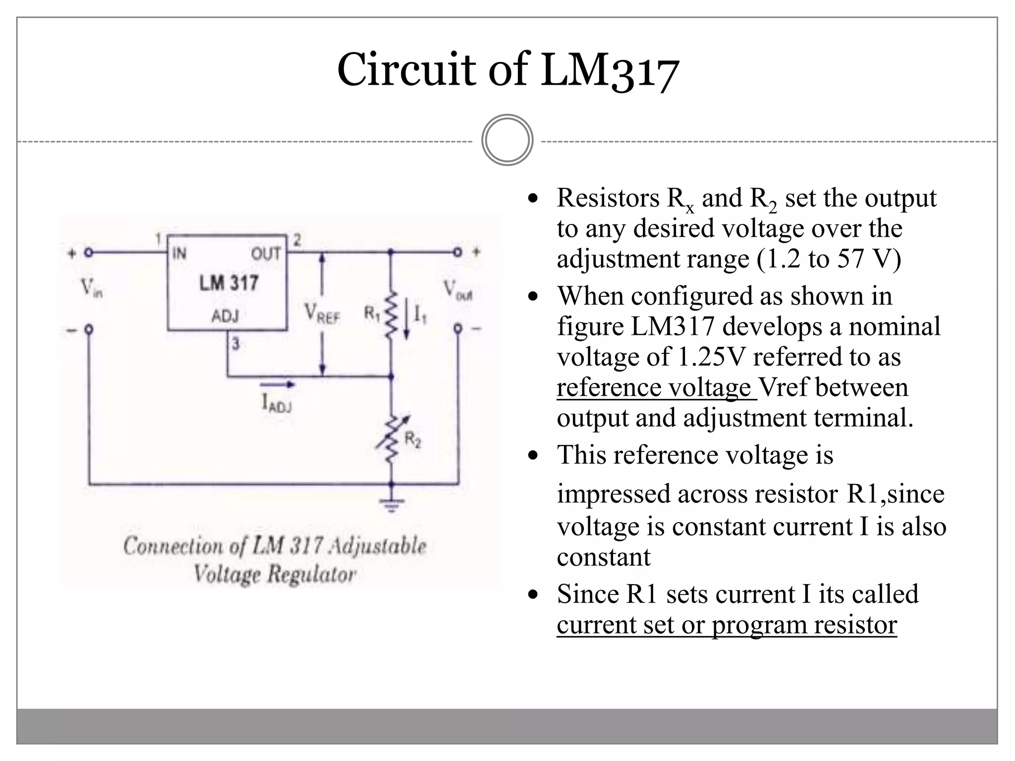
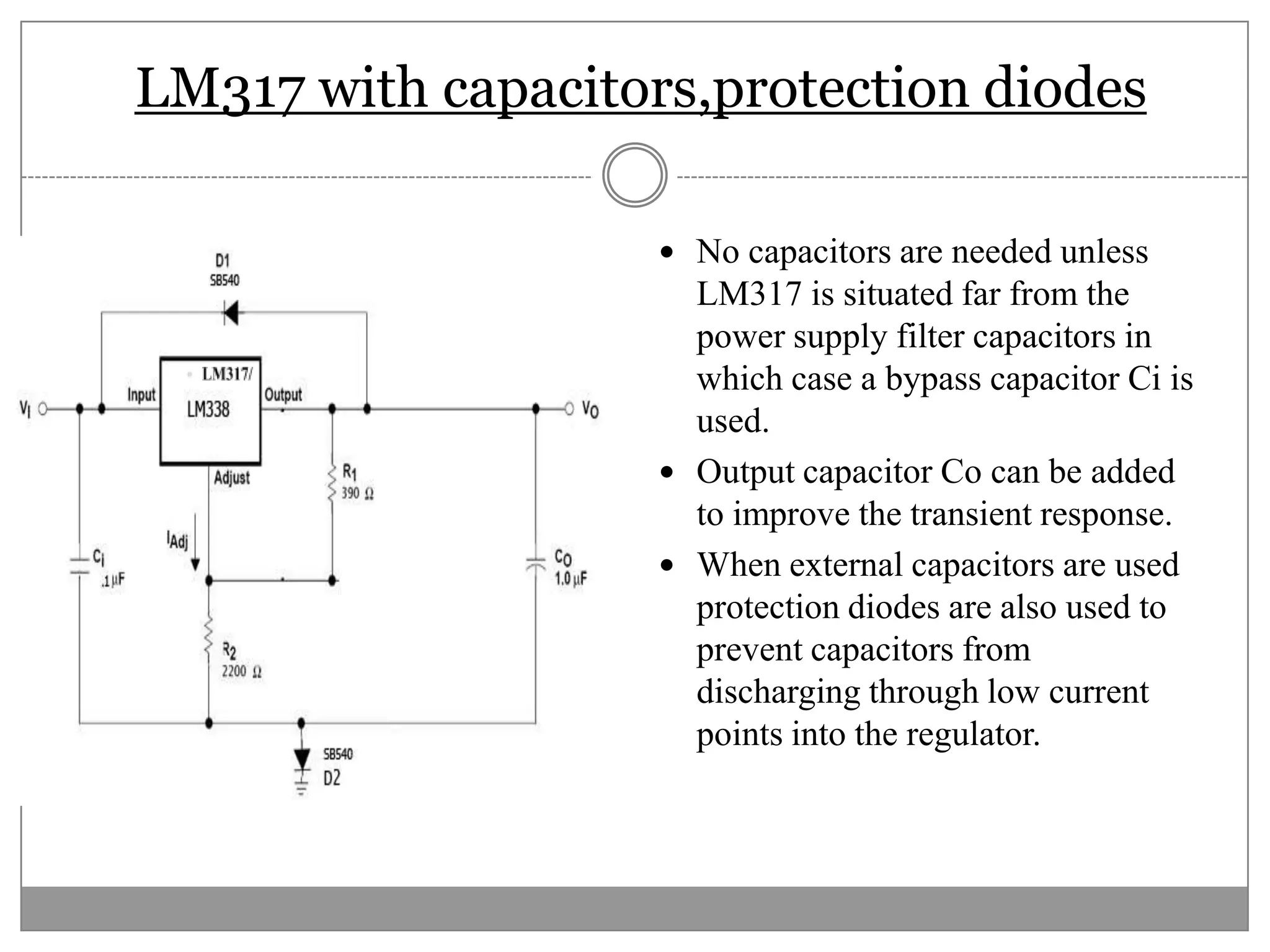
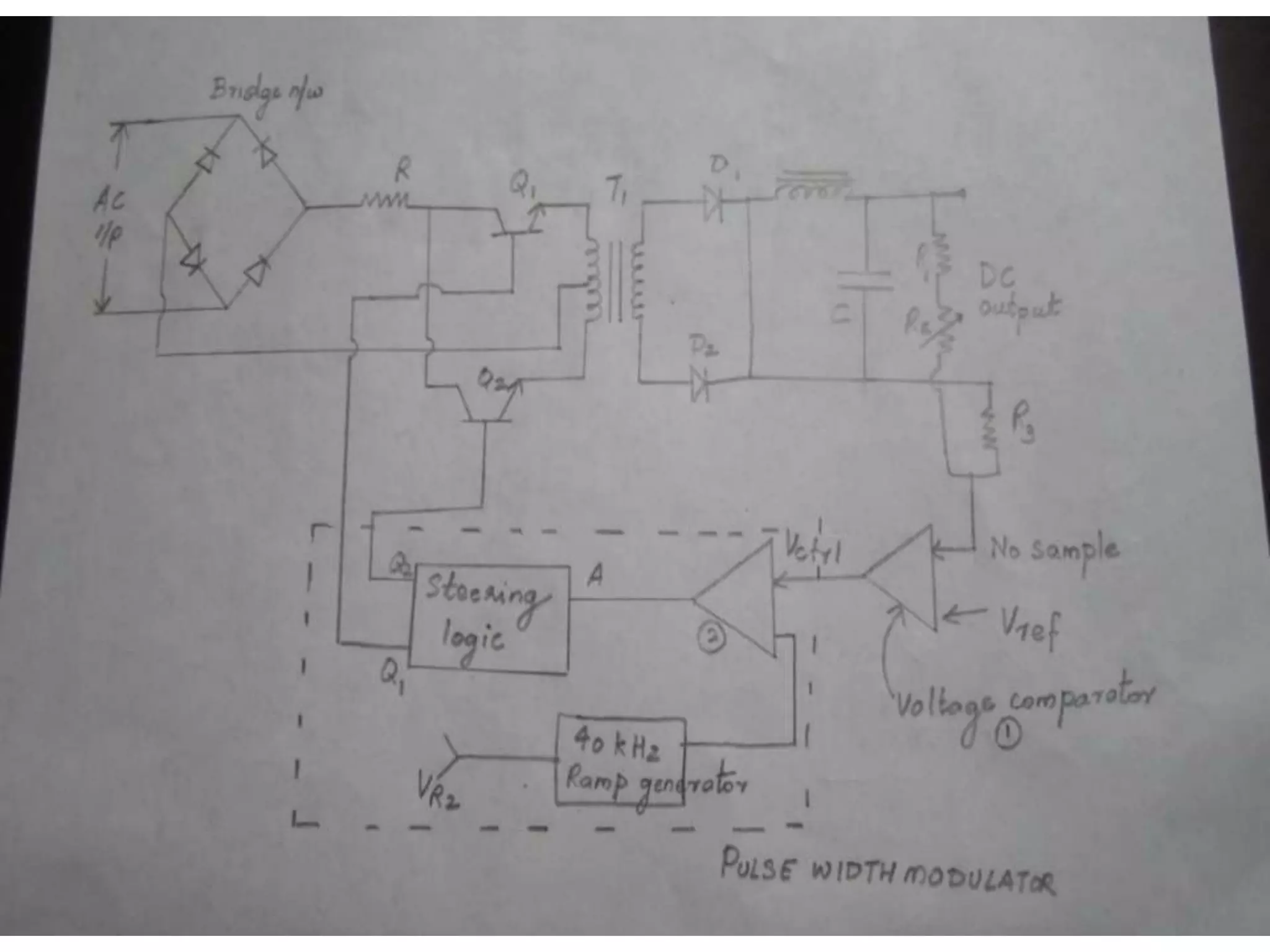
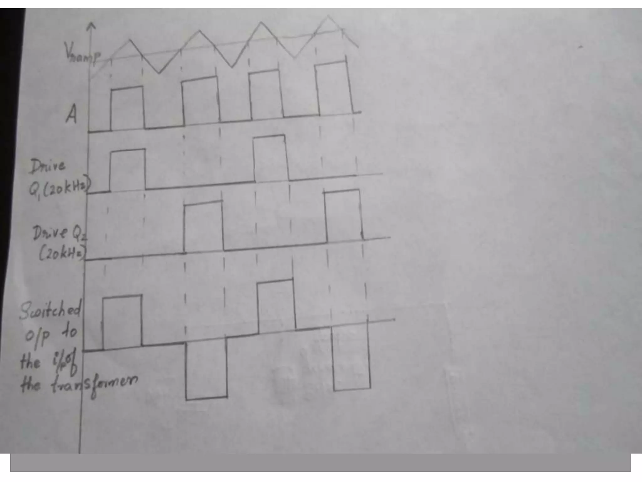
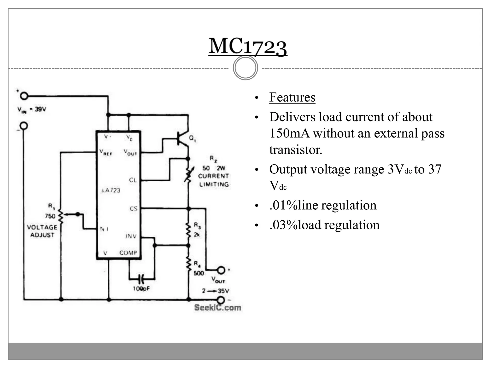
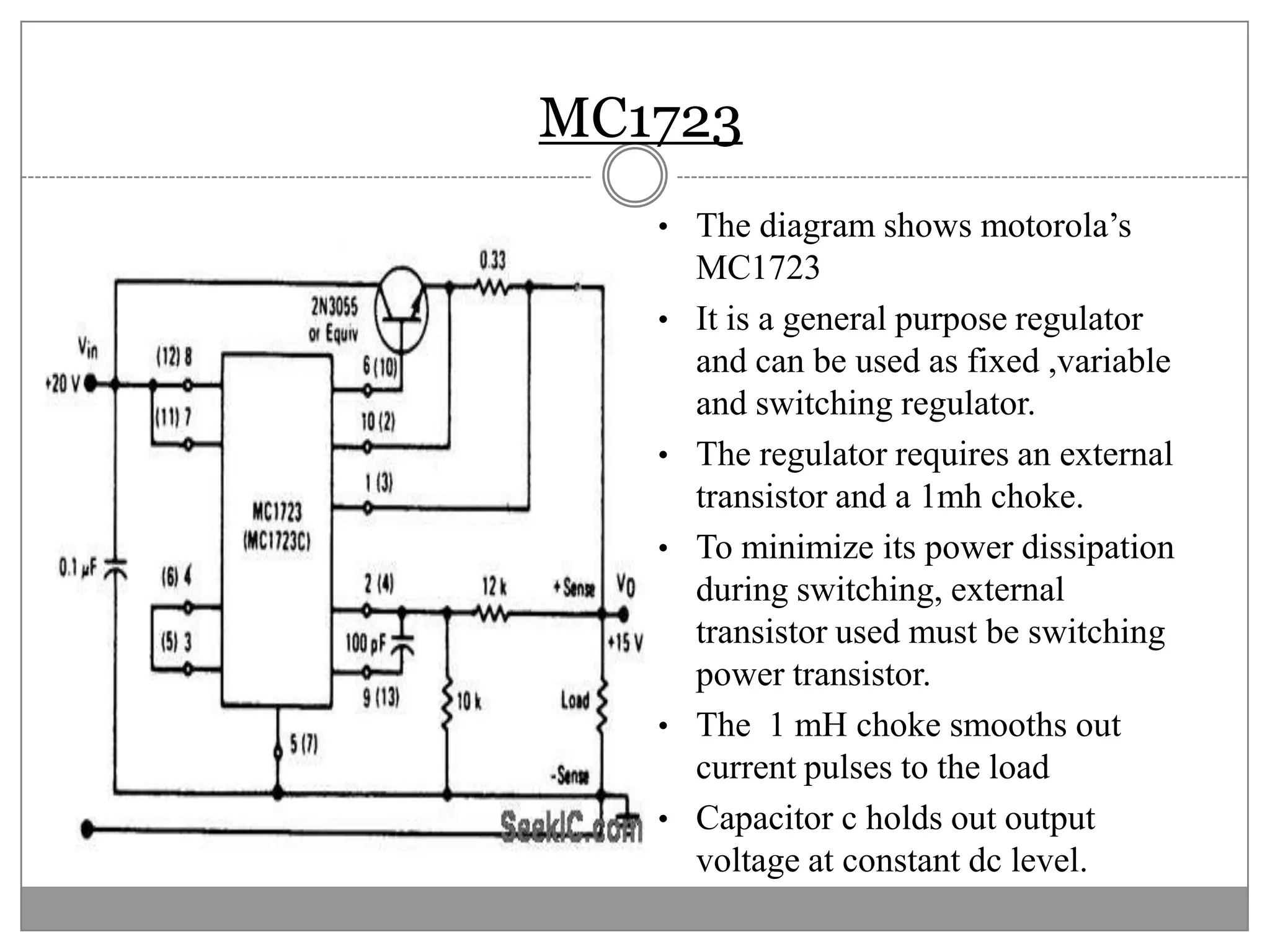


This document discusses different types of integrated circuit voltage regulators. It describes fixed voltage regulators like the 78XX and 79XX series, which provide positive and negative fixed output voltages, respectively. Adjustable voltage regulators like the LM317 allow the output voltage to be varied. Switching regulators like the MC1723 and LM723 are also covered. Key features and applications of IC voltage regulators are explained, along with basic regulator circuits and their operating principles. Performance parameters like line and load regulation are defined.