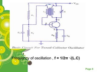
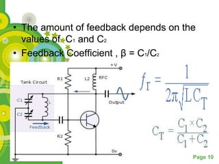
The document discusses different types of harmonic oscillators. Harmonic oscillators produce a sinusoidal output through a positive feedback loop using an electronic amplifier and filter. Key components include a tank circuit, transistor amplifier, and feedback circuit. Several oscillator circuits are described, including tuned collector, Colpitts, Hartley, phase shift, Wein bridge, and crystal oscillators. Crystal oscillators provide very stable frequencies controlled by a vibrating crystal such as quartz.
2. What is an oscillator…???
An oscillator is an electronic circuit that
produces a repetitive electronic
signal, often a sine wave or a square
wave. They are widely used in electronic
devices .
Page 2
3. Harmonic Oscillators
• The harmonic, or linear, oscillators are
those oscillators that produces
a sinusoidal output.
• The basic form of a harmonic oscillator is
an electronic amplifier connected in a
positive feedback loop with its output fed
back into its input through a filter.
Page 3
4. Essential Parts of any Oscillator
• Tank Circuit (R-C , L-C , etc.)
• Transistor Amplifier (180 phase shift)
• Feedback Circuit
Page 4
5. Barkhausen Stability Criteria
• The loop gain should be unity.
i.e Aβ = 1
• Phase shift around loop is zero or an
integral multiple of 2π (Positive
Feedback).
Page 5
6. Some Harmonic Oscillators…
Tuned Collector Oscillator
• It is called the tuned-collector oscilla-tor
because the tuned circuit (L-C circuit) is
connected to the collector of the transistor.
• The tuned circuit constitutes of the
capacitor C and inductor L.
Page 6
7. • When the supply is switched on, a transient
current is produced in the tuned L-C circuit.
• It induces voltage in L1 by mutual induction
which causes corresponding vari-ations in
base current.
• These variations in base current are
amplified β times and appear in the
collector circuit.
• A part of this amplified energy is used to
meet the losses that occur in the tank circuit
and the rest is radiated out.
Page 7
9. Colpitt’s Oscillator
• In this type of oscillator , the transistor
amplifier’s emitter is connected to the
junction of capacitors, C1 and C2 which are
connected in series and act as a simple
voltage divider.
• When the power supply is firstly
applied, capacitors C1 and C2 charge up
and then discharge through the coil L.
Page 9
10. • The amount of feedback depends on the
values of C1 and C2
• Feedback Coefficient , β = C1/C2
Page 10
11. Hartley’s Oscillator
• Widely used as local oscillator in radio
receivers.
• Hartley oscillator circuit is similar to
Colpitt’s oscillator circuit, except that
phase-shift network consists of two
inductors L1 and L2 and a capacitor C
instead of two capacitors and one
inductor.
• Feedback Fraction , β = L1/L2
Page 11
13. Phase Shift Oscillator
• The phase shift oscillator
produces positive feedback by using an
inverting amplifier and adding another
180 of phase shift with the three high-
pass filter circuits.
• The most common way of achieving this
kind of oscillation is using three identical
cascaded resistor-capacitor filters.
Page 13
15. Wein-Bridge Oscillator
• It is one of the most popular type of
oscillators used in audio frequency ranges.
• It is a two-stage amplifier with an R-C
bridge circuit.
• This type of oscillator is simple in
design, compact in size, and remarkably
stable in its frequency output.
• Furthermore, its output is relatively free
from distortion and its fre-quency can be
varied easily.
Page 15
16. • The overall gain is high because of use of
two transistors.
• When C1 = C2 = C
and R1 = R2 = R
Page 16
17. Crystal Oscillator
• This is a type of oscillator that is controlled
by a crystal.
• The big advantage of a crystal oscillator is
high frequency stablility. Common crystals
used are Rochelle salts and quartz.
• The natural frequency of a crystal's
vibrations is found to be more constant
than the oscillations in a LC circuit.
Natural Ferquency = K/T
where K = cut angle constant
and T = thickness of crystal
Page 17
18. • The LC circuit is the electricial equilavent of
the crystal.
• It has limited power output.
• Crystals will overheat or crack when fed
with too much voltage. The current flowing
through a crystal generally should not be
more than 100mA (.1A)
• Frequencies :-
• Series resonant Frequency , fs =1/2π √(L.C)
• Parallel Resonant Frequency
Page 18