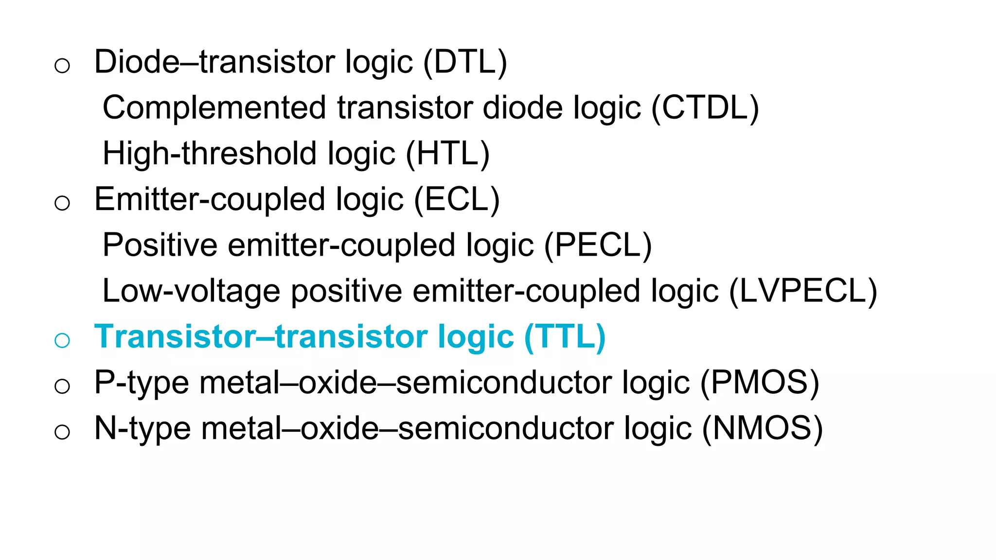
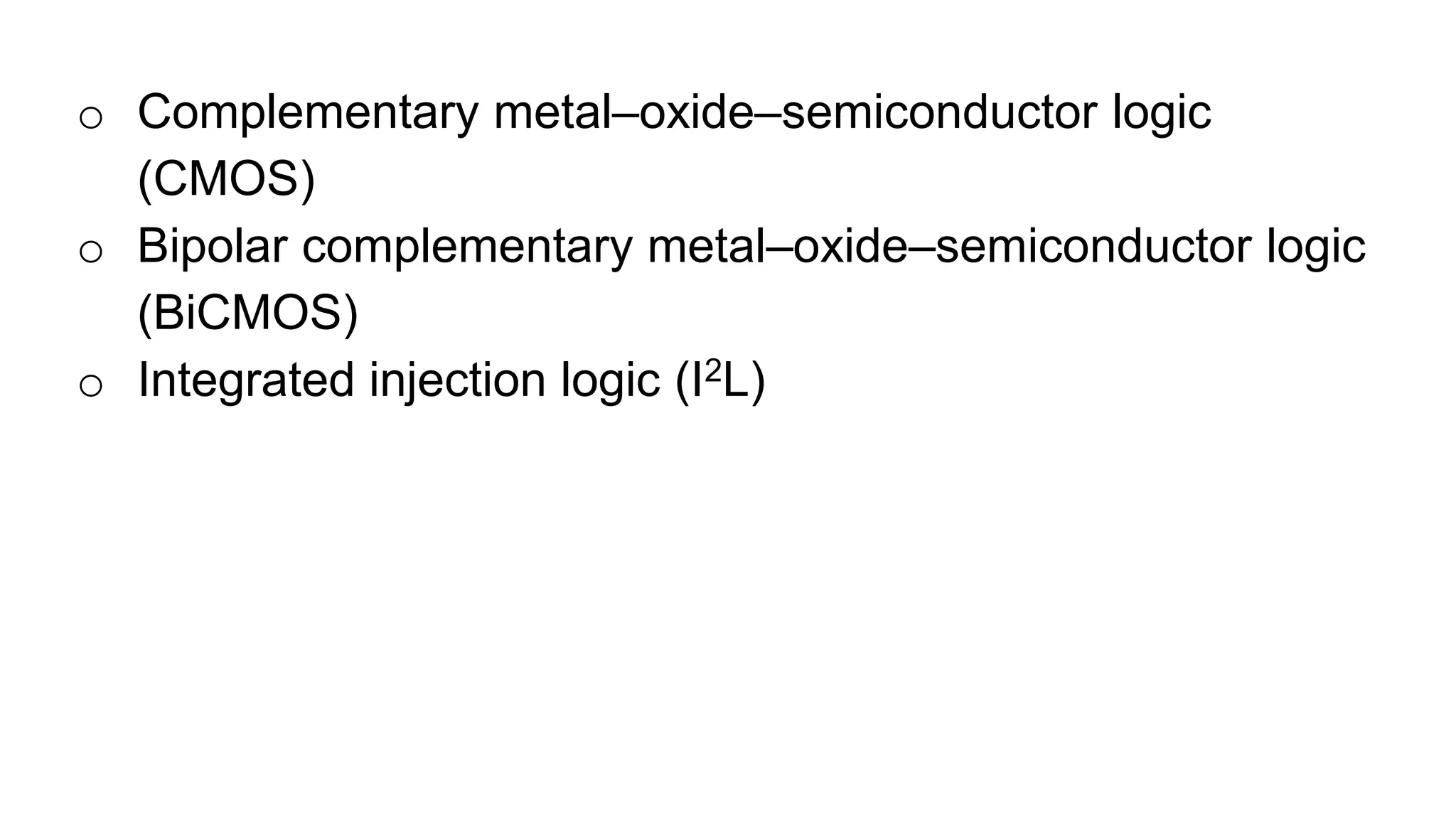
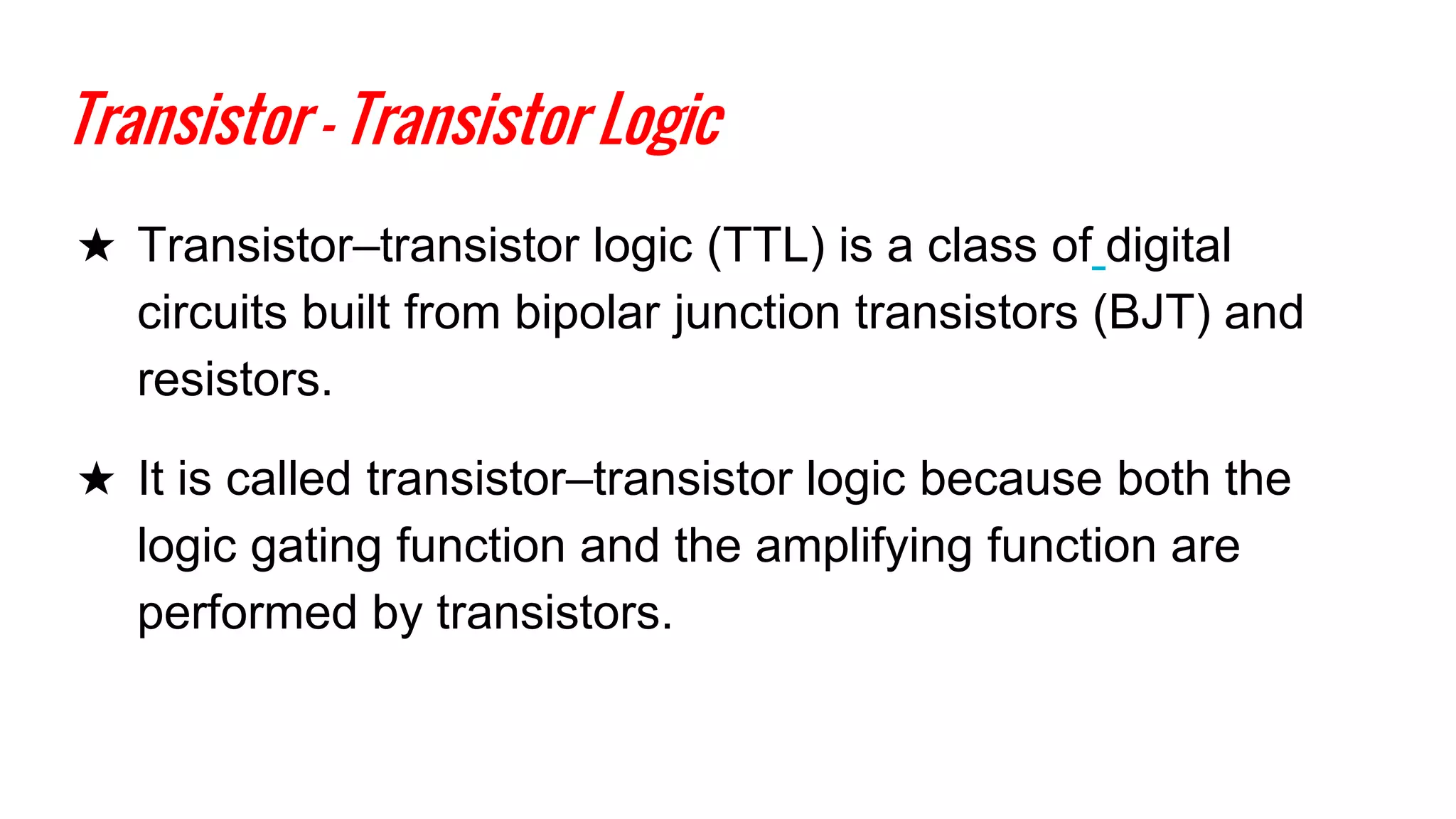
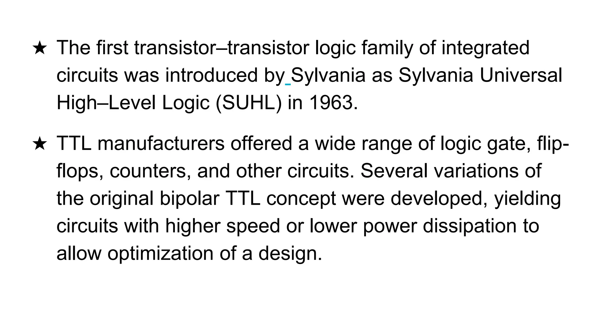
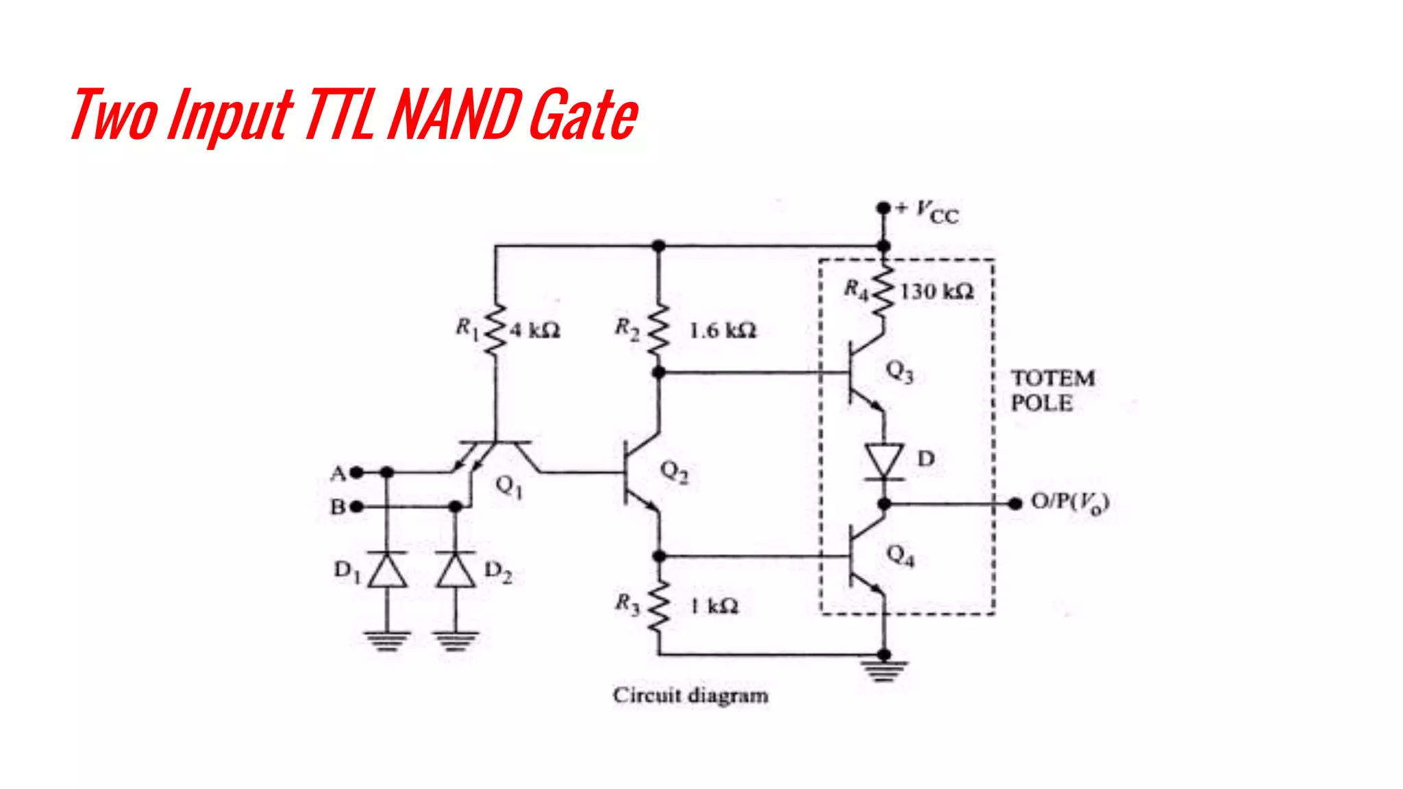
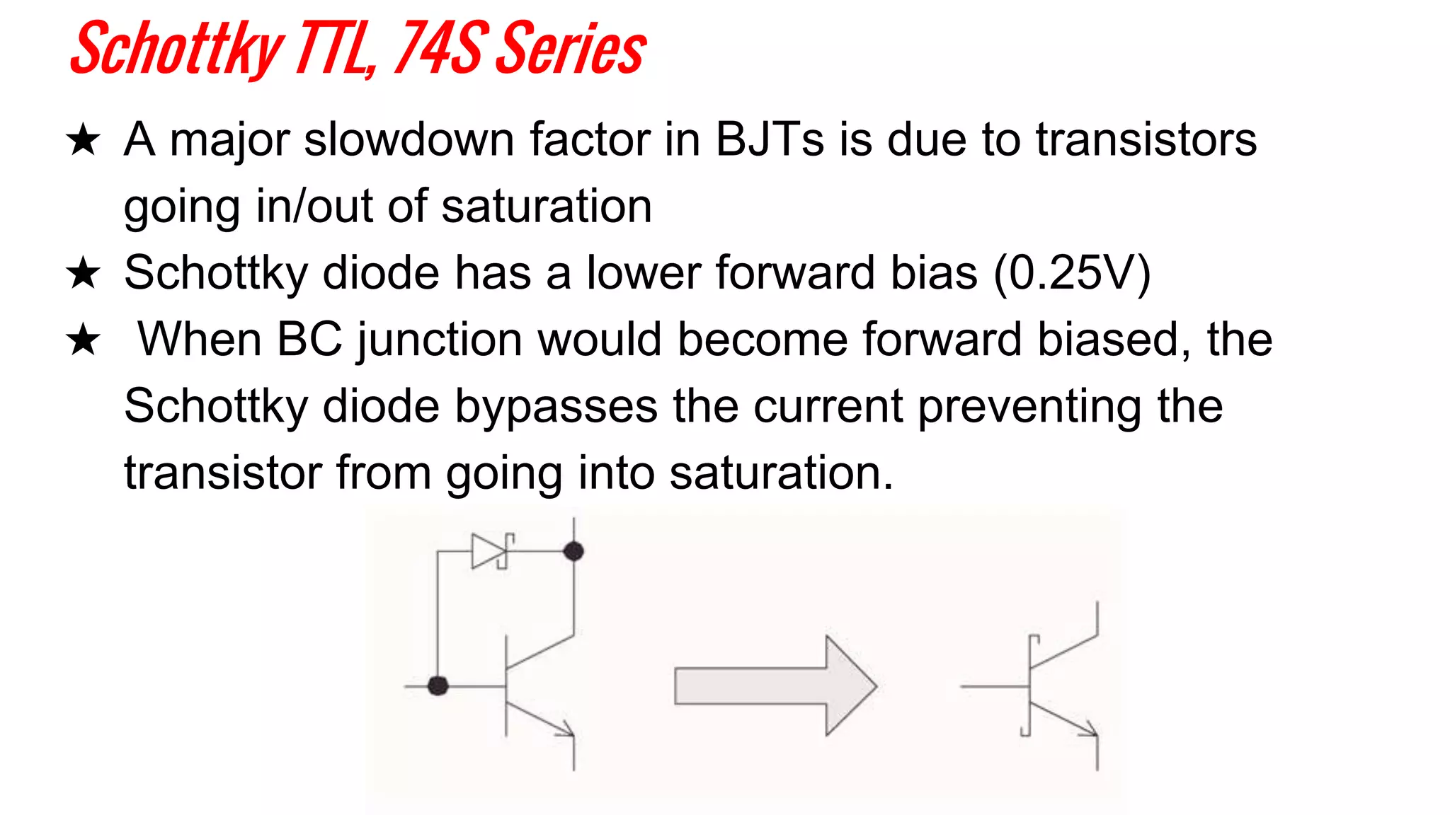
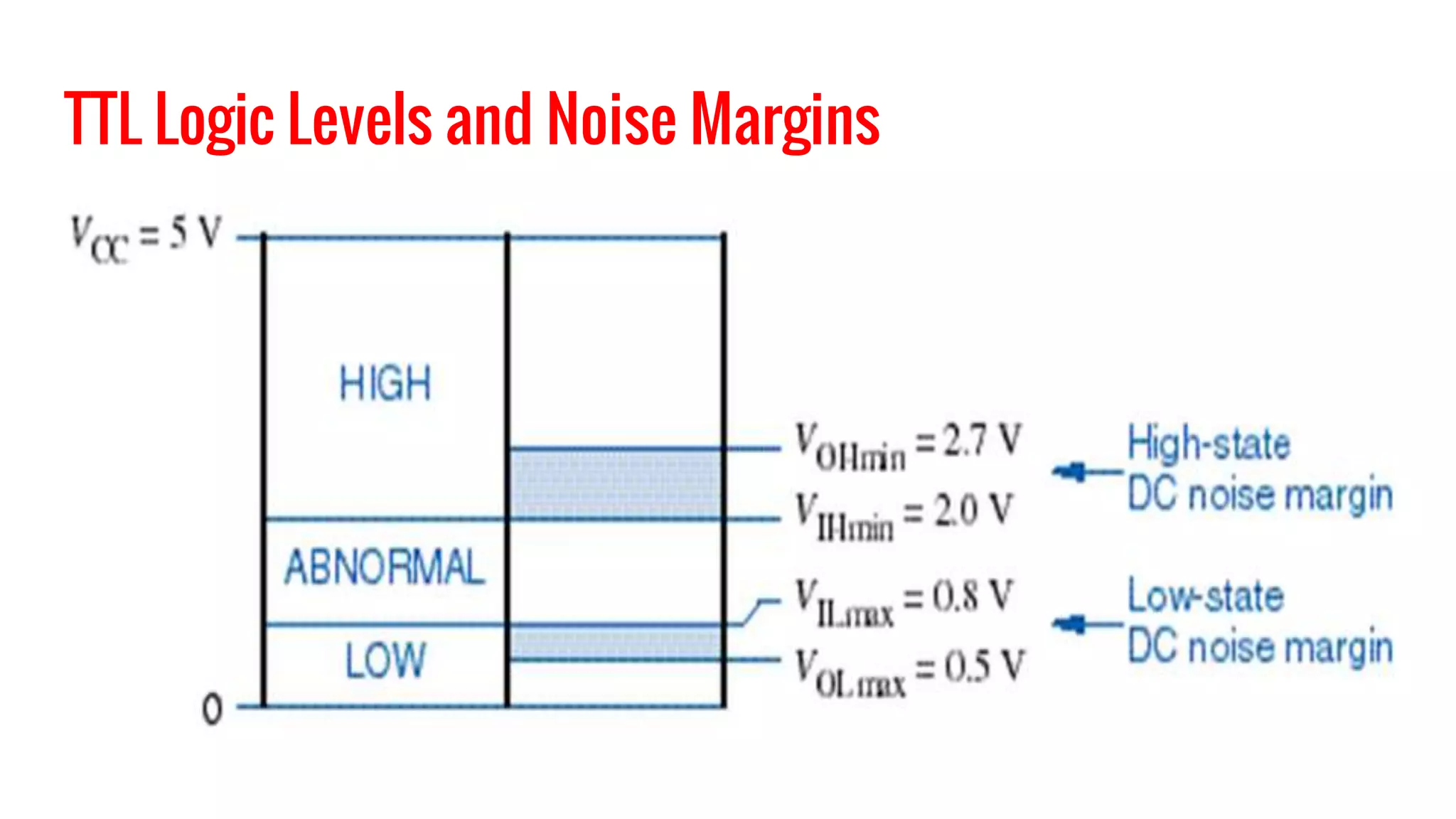
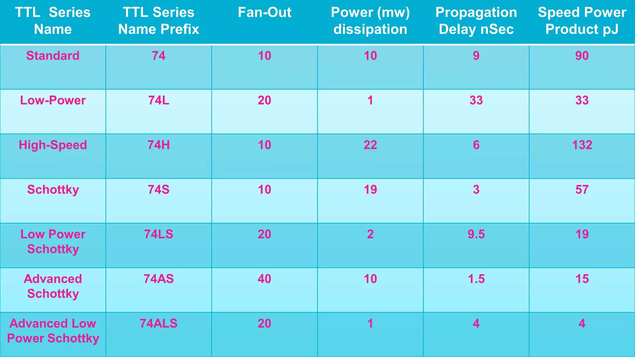
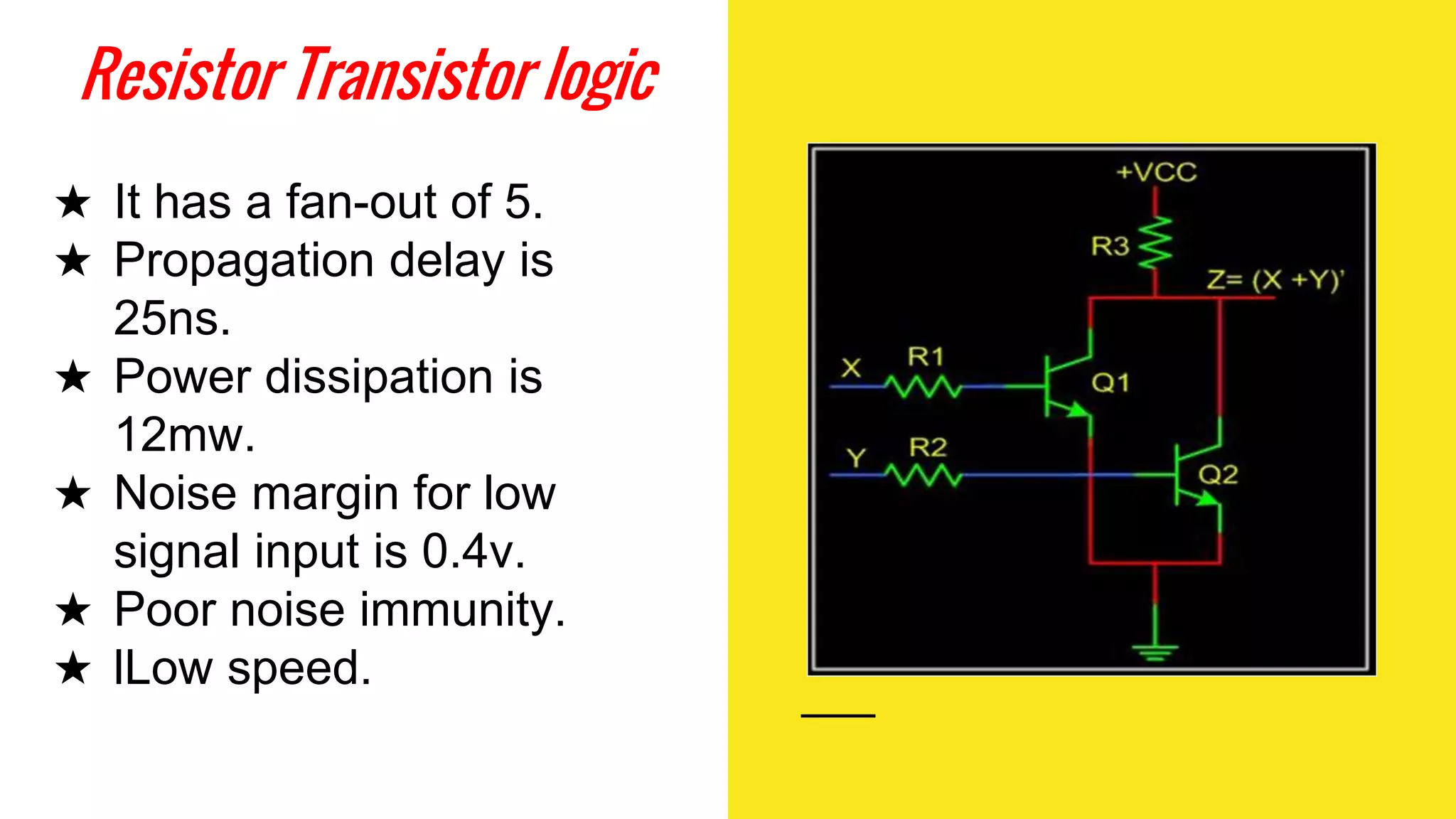
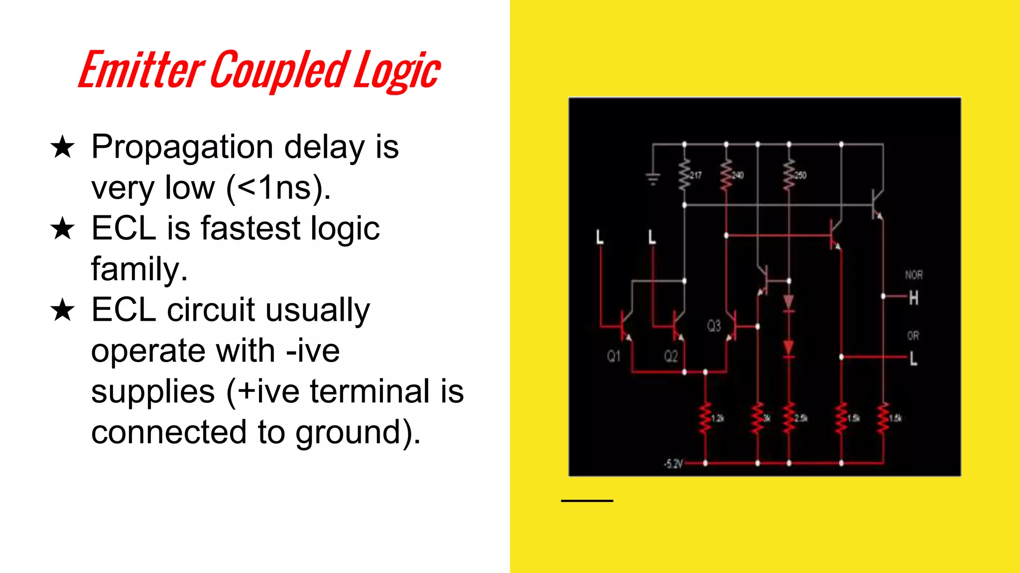
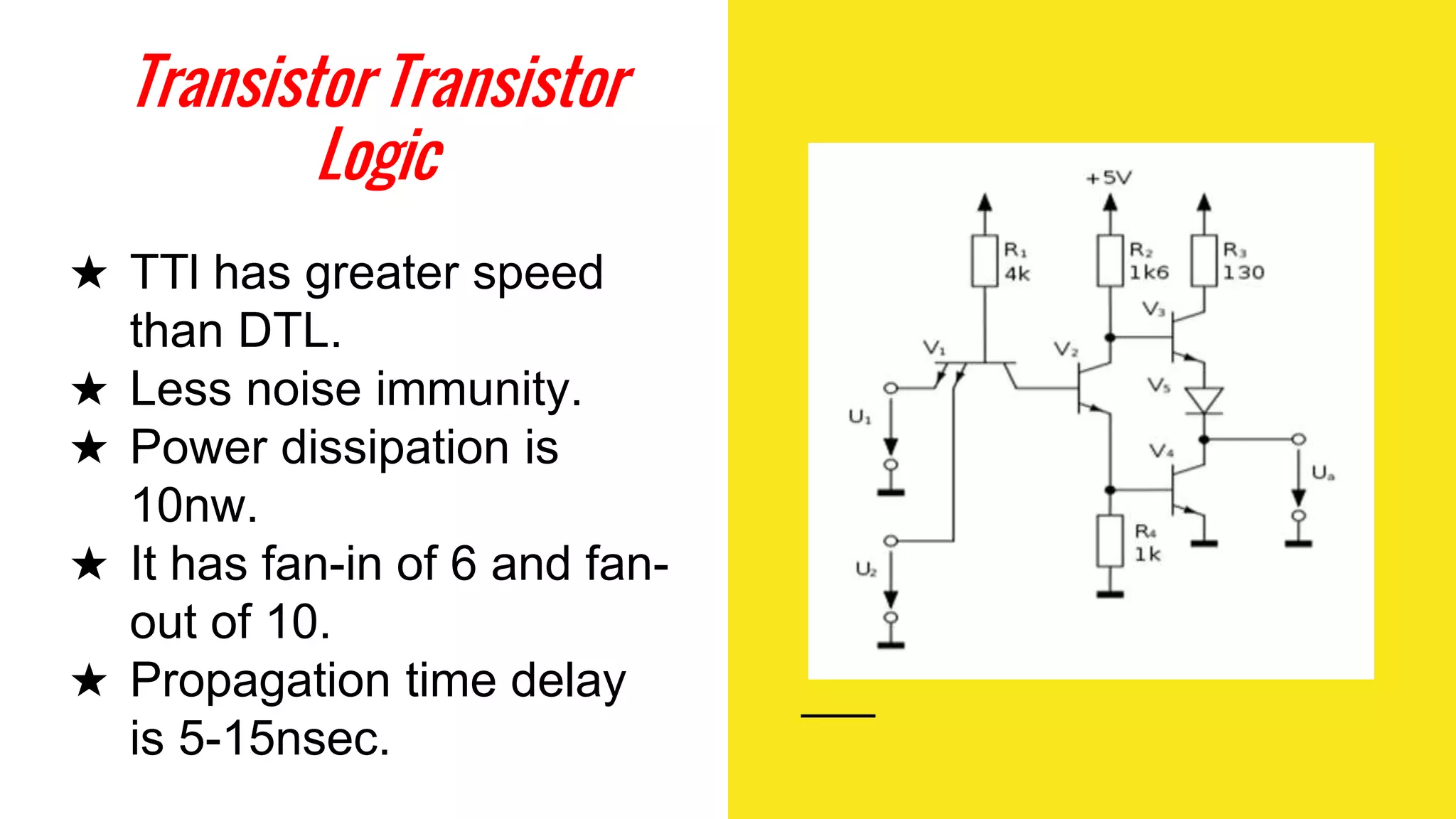
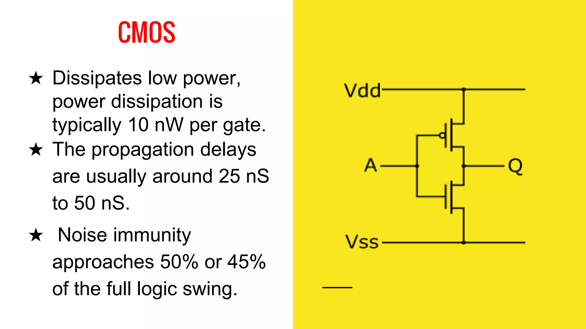
Dayalbagh Educational
Institute
D.Surat
M.Sc. Physics
Transistor
Transistor
Logic
Introduction
Introduction to Digital logic
gates
Technologies
Transistor Transistor Logic
7400 TTL Series
TTL Sub-families
Two Input TTL NAND Gate
TTL Logic Levels and Noise
Margins
TTL Family Evolution
Comparison to logic families
Introduction to Digital logic Gates
★ A Digital Logic Gate is an electronic device that makes
logical decisions based on the different combinations of
digital signals present on its inputs.
★ Digital logic gates may have more than one input but
generally only have one digital output.
★ Individual logic gates can be connected together to form
combinational or sequential circuits, or larger logic gate
functions.
Technologies
★ The list of packaged building-block logic families can be
divided into categories, listed here in roughly
chronological order of introduction, along with their usual
abbreviations:
o Resistor–transistor logic (RTL)
• Direct-coupled transistor logic (DCTL)
• Resistor–capacitor–transistor logic (RCTL)
o Diode–transistor logic (DTL)
Complemented transistor diode logic (CTDL)
High-threshold logic (HTL)
o Emitter-coupled logic (ECL)
Positive emitter-coupled logic (PECL)
Low-voltage positive emitter-coupled logic (LVPECL)
o Transistor–transistor logic (TTL)
o P-type metal–oxide–semiconductor logic (PMOS)
o N-type metal–oxide–semiconductor logic (NMOS)
o Complementary metal–oxide–semiconductor logic
(CMOS)
o Bipolar complementary metal–oxide–semiconductor logic
(BiCMOS)
o Integrated injection logic (I2L)
Transistor - Transistor Logic
★ Transistor–transistor logic (TTL) is a class of digital
circuits built from bipolar junction transistors (BJT) and
resistors.
★ It is called transistor–transistor logic because both the
logic gating function and the amplifying function are
performed by transistors.
★ The first transistor–transistor logic family of integrated
circuits was introduced by Sylvania as Sylvania Universal
High–Level Logic (SUHL) in 1963.
★ TTL manufacturers offered a wide range of logic gate, flip-
flops, counters, and other circuits. Several variations of
the original bipolar TTL concept were developed, yielding
circuits with higher speed or lower power dissipation to
allow optimization of a design.
★ The design of the input and outputs of TTL gates allowed
many elements to be interconnected.
★ Transistor-transistor logic (TTL) is a digital logic design in
which bipolar transistor s act on direct-current pulses.
★ Many TTL logic gate s are typically fabricated onto a
single integrated circuit (IC).
★ TTL ICs usually have four-digit numbers beginning with
74 or 54.
★ A TTL device employs transistors with multiple emitters in
gates having more than one input.
7400 TTL Series
★ TTL ICs first developed in 1965 and they are known as
“standard TTL” . This version of TTL circuit is not
available now.
★ TTL family use only transistor to perform the basic logic
operations.
★ The standard TTL is improved to a great extent over the
year.
★ TTL devices are still used as “glue” logic which connects
more complex devices in digital system.
TTL Sub-families
★ There are several subfamilies or series of the TTL technology
such as
★ Standard(74)
★ Low-power(74L),
★ High-speed(74H),
★ Schottky(74S),
★ Low-power Schottky(74LS),
★ Advanced Schottky (74AS),
★ Advanced low-power Schottky (74ALS).
Contd...
★ Commercial TTL ICs have a number designation that
starts with 74 and follows with a suffix that identifies the
series type. Examples are 7404, 74S86, and 74ALS161.
★ The speed-power product is an important parameter for
comparing the various TTL series.
★ This is the product of the propagation delay and power
dissipation and is measured in picojoules (pJ).
★ The propagation delay of a transistor circuit that goes into
saturation depends mostly on two factors:
○ storage time
○ RC time constants.
★ A pulse through a gate take certain amount of time from
input to output. This interval of time is known as
propagation time.
Two Input TTL NAND Gate
Standard TTL 74 Series
★ Offer a combination of speed and dissipation suited for
many applications.
★ The 54 series is the counterpart of 74 series.
Low Power TTL, 74L series
★ Essentially the same basic circuit as the standard 74
series except that all resistance values (R1=40k R2=20k
R3=12k R4=500) are increased.
★ Large resistance reduce the current and therefore, the
power requirement,But at the expense of reduction in
speed.
★ The power consumption of Low power TTL is about 1/10
of that of standard TTL.
High Speed TTL, 74H Series
★ Essentially the same basic circuit as the standard 74
series except that smaller resistance values (R1=2.8k
R2=760 R3=470 R4=58) are used and the emitter follower
transistor Q3 is replaced by Darlington pair and emitter to
base joining of Darlington pair (Q5-Q3) is connected to
ground through a resistor of 4k.
★ The switching speed of 74H series is approximately two
times more than that of standard TTL.
Schottky TTL, 74S Series
★ A major slowdown factor in BJTs is due to transistors
going in/out of saturation
★ Schottky diode has a lower forward bias (0.25V)
★ When BC junction would become forward biased, the
Schottky diode bypasses the current preventing the
transistor from going into saturation.
Low Power Schottky TTL, 74LS Series
★ Lower power and slower speed version of 74S series.
★ It uses the schottky clamped transistor, but with larger
resistance values than those in the 74S series.
TTL Logic Levels and Noise Margins
TTL Series
Name
TTL Series
Name Prefix
Fan-Out Power (mw)
dissipation
Propagation
Delay nSec
Speed Power
Product pJ
Standard 74 10 10 9 90
Low-Power 74L 20 1 33 33
High-Speed 74H 10 22 6 132
Schottky 74S 10 19 3 57
Low Power
Schottky
74LS 20 2 9.5 19
Advanced
Schottky
74AS 40 10 1.5 15
Advanced Low
Power Schottky
74ALS 20 1 4 4
TTL family evolution
Comparison to
logic families
Resistor Transistor logic
★ It has a fan-out of 5.
★ Propagation delay is
25ns.
★ Power dissipation is
12mw.
★ Noise margin for low
signal input is 0.4v.
★ Poor noise immunity.
★ lLow speed.
Diode Transistor Logic
★ It has fan-out of 8.
★ It has high noise
immunity.
★ Power dissipation is
12mw.
★ Propagation constant is
average 30ns.
★ Noise margin is about
0.7v.
Emitter Coupled Logic
★ Propagation delay is
very low (<1ns).
★ ECL is fastest logic
family.
★ ECL circuit usually
operate with -ive
supplies (+ive terminal is
connected to ground).
Transistor Transistor
Logic
★ TTl has greater speed
than DTL.
★ Less noise immunity.
★ Power dissipation is
10nw.
★ It has fan-in of 6 and fan-
out of 10.
★ Propagation time delay
is 5-15nsec.
CMOS
★ Dissipates low power,
power dissipation is
typically 10 nW per gate.
★ The propagation delays
are usually around 25 nS
to 50 nS.
★ Noise immunity
approaches 50% or 45%
of the full logic swing.
Online Sources
www.wikipedia.com
www.allaboutcircuits.com
www.electrical4u.com
Books Refered
FUNDAMENTALS OF DIGITAL CIRCUITS
By A. ANAND KUMAR
Thank You...

Transistor Transistor Logic

  • 2.
  • 3.
  • 4.
    Introduction Introduction to Digitallogic gates Technologies Transistor Transistor Logic 7400 TTL Series TTL Sub-families Two Input TTL NAND Gate TTL Logic Levels and Noise Margins TTL Family Evolution Comparison to logic families
  • 5.
    Introduction to Digitallogic Gates ★ A Digital Logic Gate is an electronic device that makes logical decisions based on the different combinations of digital signals present on its inputs. ★ Digital logic gates may have more than one input but generally only have one digital output. ★ Individual logic gates can be connected together to form combinational or sequential circuits, or larger logic gate functions.
  • 6.
    Technologies ★ The listof packaged building-block logic families can be divided into categories, listed here in roughly chronological order of introduction, along with their usual abbreviations: o Resistor–transistor logic (RTL) • Direct-coupled transistor logic (DCTL) • Resistor–capacitor–transistor logic (RCTL)
  • 7.
    o Diode–transistor logic(DTL) Complemented transistor diode logic (CTDL) High-threshold logic (HTL) o Emitter-coupled logic (ECL) Positive emitter-coupled logic (PECL) Low-voltage positive emitter-coupled logic (LVPECL) o Transistor–transistor logic (TTL) o P-type metal–oxide–semiconductor logic (PMOS) o N-type metal–oxide–semiconductor logic (NMOS)
  • 8.
    o Complementary metal–oxide–semiconductorlogic (CMOS) o Bipolar complementary metal–oxide–semiconductor logic (BiCMOS) o Integrated injection logic (I2L)
  • 9.
    Transistor - TransistorLogic ★ Transistor–transistor logic (TTL) is a class of digital circuits built from bipolar junction transistors (BJT) and resistors. ★ It is called transistor–transistor logic because both the logic gating function and the amplifying function are performed by transistors.
  • 10.
    ★ The firsttransistor–transistor logic family of integrated circuits was introduced by Sylvania as Sylvania Universal High–Level Logic (SUHL) in 1963. ★ TTL manufacturers offered a wide range of logic gate, flip- flops, counters, and other circuits. Several variations of the original bipolar TTL concept were developed, yielding circuits with higher speed or lower power dissipation to allow optimization of a design.
  • 11.
    ★ The designof the input and outputs of TTL gates allowed many elements to be interconnected. ★ Transistor-transistor logic (TTL) is a digital logic design in which bipolar transistor s act on direct-current pulses. ★ Many TTL logic gate s are typically fabricated onto a single integrated circuit (IC). ★ TTL ICs usually have four-digit numbers beginning with 74 or 54. ★ A TTL device employs transistors with multiple emitters in gates having more than one input.
  • 12.
    7400 TTL Series ★TTL ICs first developed in 1965 and they are known as “standard TTL” . This version of TTL circuit is not available now. ★ TTL family use only transistor to perform the basic logic operations. ★ The standard TTL is improved to a great extent over the year. ★ TTL devices are still used as “glue” logic which connects more complex devices in digital system.
  • 13.
    TTL Sub-families ★ Thereare several subfamilies or series of the TTL technology such as ★ Standard(74) ★ Low-power(74L), ★ High-speed(74H), ★ Schottky(74S), ★ Low-power Schottky(74LS), ★ Advanced Schottky (74AS), ★ Advanced low-power Schottky (74ALS).
  • 14.
    Contd... ★ Commercial TTLICs have a number designation that starts with 74 and follows with a suffix that identifies the series type. Examples are 7404, 74S86, and 74ALS161. ★ The speed-power product is an important parameter for comparing the various TTL series. ★ This is the product of the propagation delay and power dissipation and is measured in picojoules (pJ).
  • 15.
    ★ The propagationdelay of a transistor circuit that goes into saturation depends mostly on two factors: ○ storage time ○ RC time constants. ★ A pulse through a gate take certain amount of time from input to output. This interval of time is known as propagation time.
  • 16.
    Two Input TTLNAND Gate
  • 17.
    Standard TTL 74Series ★ Offer a combination of speed and dissipation suited for many applications. ★ The 54 series is the counterpart of 74 series.
  • 18.
    Low Power TTL,74L series ★ Essentially the same basic circuit as the standard 74 series except that all resistance values (R1=40k R2=20k R3=12k R4=500) are increased. ★ Large resistance reduce the current and therefore, the power requirement,But at the expense of reduction in speed. ★ The power consumption of Low power TTL is about 1/10 of that of standard TTL.
  • 19.
    High Speed TTL,74H Series ★ Essentially the same basic circuit as the standard 74 series except that smaller resistance values (R1=2.8k R2=760 R3=470 R4=58) are used and the emitter follower transistor Q3 is replaced by Darlington pair and emitter to base joining of Darlington pair (Q5-Q3) is connected to ground through a resistor of 4k. ★ The switching speed of 74H series is approximately two times more than that of standard TTL.
  • 20.
    Schottky TTL, 74SSeries ★ A major slowdown factor in BJTs is due to transistors going in/out of saturation ★ Schottky diode has a lower forward bias (0.25V) ★ When BC junction would become forward biased, the Schottky diode bypasses the current preventing the transistor from going into saturation.
  • 21.
    Low Power SchottkyTTL, 74LS Series ★ Lower power and slower speed version of 74S series. ★ It uses the schottky clamped transistor, but with larger resistance values than those in the 74S series.
  • 22.
    TTL Logic Levelsand Noise Margins
  • 23.
    TTL Series Name TTL Series NamePrefix Fan-Out Power (mw) dissipation Propagation Delay nSec Speed Power Product pJ Standard 74 10 10 9 90 Low-Power 74L 20 1 33 33 High-Speed 74H 10 22 6 132 Schottky 74S 10 19 3 57 Low Power Schottky 74LS 20 2 9.5 19 Advanced Schottky 74AS 40 10 1.5 15 Advanced Low Power Schottky 74ALS 20 1 4 4
  • 24.
  • 26.
  • 27.
    Resistor Transistor logic ★It has a fan-out of 5. ★ Propagation delay is 25ns. ★ Power dissipation is 12mw. ★ Noise margin for low signal input is 0.4v. ★ Poor noise immunity. ★ lLow speed.
  • 28.
    Diode Transistor Logic ★It has fan-out of 8. ★ It has high noise immunity. ★ Power dissipation is 12mw. ★ Propagation constant is average 30ns. ★ Noise margin is about 0.7v.
  • 29.
    Emitter Coupled Logic ★Propagation delay is very low (<1ns). ★ ECL is fastest logic family. ★ ECL circuit usually operate with -ive supplies (+ive terminal is connected to ground).
  • 30.
    Transistor Transistor Logic ★ TTlhas greater speed than DTL. ★ Less noise immunity. ★ Power dissipation is 10nw. ★ It has fan-in of 6 and fan- out of 10. ★ Propagation time delay is 5-15nsec.
  • 31.
    CMOS ★ Dissipates lowpower, power dissipation is typically 10 nW per gate. ★ The propagation delays are usually around 25 nS to 50 nS. ★ Noise immunity approaches 50% or 45% of the full logic swing.
  • 32.
  • 33.