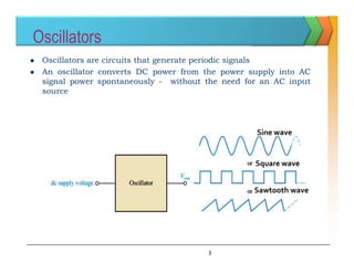
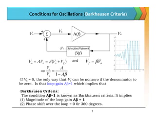
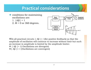
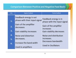
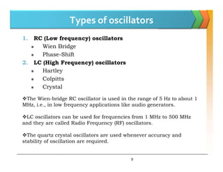
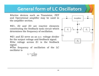
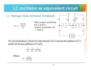
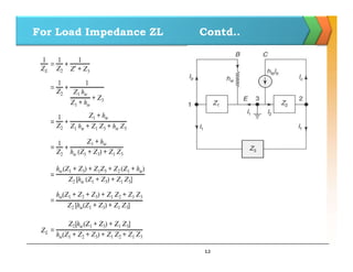
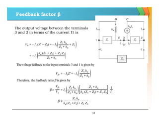
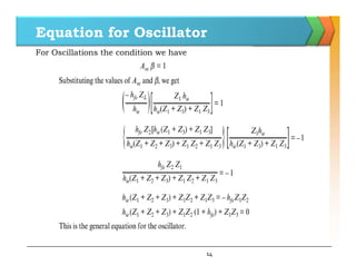
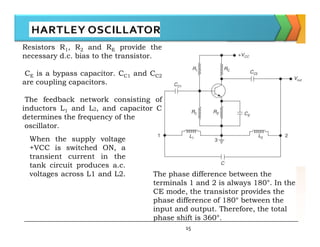
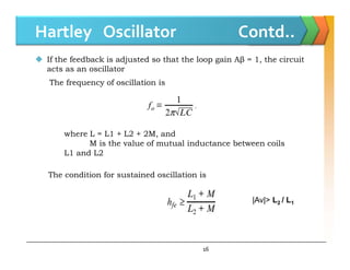
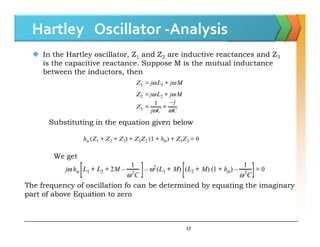
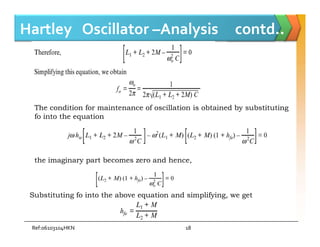
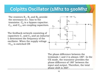
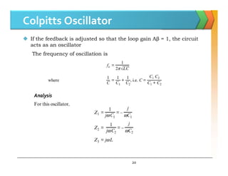
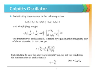
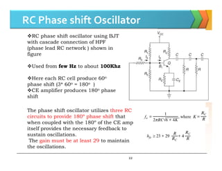
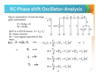
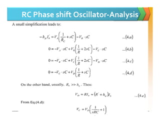
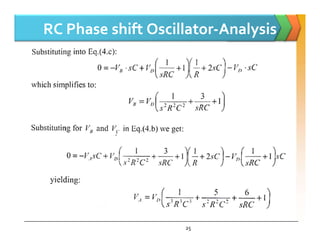
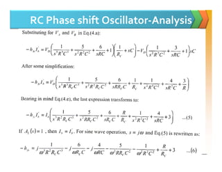
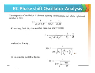
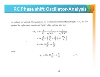
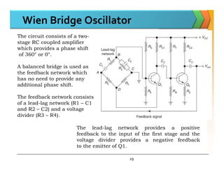
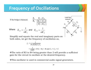
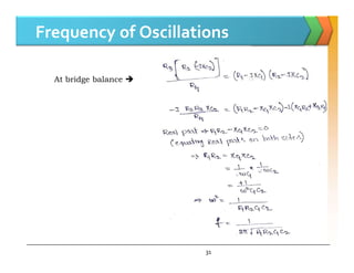
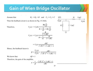
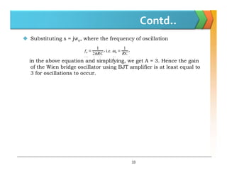
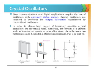
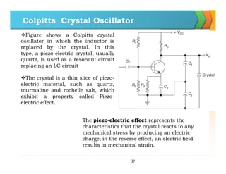
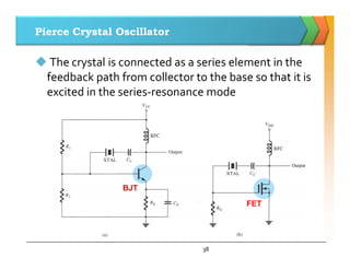
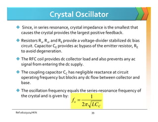
Positive feedback Amplifiers
1
Reference: Electronic Devices And Circuits by S. Salivahanan
N Suresh Kumar
Introduction
 Oscillation: an effect that repeatedly and regularly fluctuates
about the mean value
 Oscillator: circuit that produces oscillation
 These signals serve a variety of purposes such as Communications
systems, digital systems (including computers), and test equipment
make use of oscillators
 Oscillators are used to generate signals, e.g.
 Used as a local oscillator to transform the RF signals to IF
signals in a receiver;
 Used to generate RF carrier in a transmitter
 Used to generate clocks in digital systems;
 Used as sweep circuits in TV sets and CRO.
2
Oscillators
 Oscillators are circuits that generate periodic signals
 An oscillator converts DC power from the power supply into AC
signal power spontaneously - without the need for an AC input
source
Sine wave
Sine wave
Square wave
Sawtooth wave
3
Classification of Oscillators
1. According to the waveforms generated:
(a) Sinusoidal oscillator (b) Relaxation oscillator
2. According to the fundamental mechanisms involved:
(a) Negative resistance oscillators (b) Feedback oscillators
3. According to the frequency generated:
(a) Audio frequency oscillator (AFO): up to 20 kHz
(b) Radio frequency oscillator (RFO): 20 kHz to 30 MHz
(c) Very high frequency (VHF) oscillator: 30 MHz to 300 MHz
(d) Ultra high frequency (UHF) oscillator: 300 MHz to 3 GHz
(e) Microwave frequency oscillator: above 3 GHz
4. According to the type of circuit used, sine-wave oscillators may be
classified as
(a) LC tuned oscillator , (b) RC phase shift oscillator.
4
Conditions for Oscillations (Barkhausen Criteria)

+
+
SelectiveNetwork
(f)
Vf
Vs Vo
V
A(f)
)
( V
V
A
AV
V 

 and V
V 

5
)
( f
s
o V
V
A
AV
V 

 
and
o
f V
V 


A
A
V
V
s
o



1
If Vs = 0, the only way that Vo can be nonzero if the denominator to
be zero. Is that loop gain A=1 which implies that
Barkhausen Criteria:
The condition Aβ=1 is known as Barkhausen criteria. It implies
(1) Magnitude of the loop gain Aβ = 1
(2) Phase shift over the loop = 0 0r 360 degrees.
Mechanism for start of Oscillation
 The oscillator circuit is set into oscillations by a random variation
caused in the base current due to noise component or a small
variation in the d.c. power supply.
 The noise components in a transistor will cause some small signal at
the output of the amplifier. Even when no external signal is applied
 The output signal caused by noise signals will be predominantly at
fo.
 If a small fraction (beta ) of the output signal is fed back to the
6
 If a small fraction (beta ) of the output signal is fed back to the
input with proper phase relation, then this feedback signal will be
amplified by the amplifier. If the amplifier has a gain of more than
1/β, then the output increases and thereby the feed back signal
becomes larger.
 This process continues and the output goes on increasing. But as
the signal level increases, the gain of the amplifier decreases and at
a particular value of output, the gain of the amplifier is reduced
exactly equal to 1/β. Then the output voltage remains constant at
frequency fo, called frequency of oscillation.
Practical considerations
 conditions for maintaining
oscillations are:
1. |Aβ| = 1
2. Φ = 0 or 360 degrees.
7
In all practical circuits | Aβ |> 1(for positive feedback) so that the
amplitude of oscillation will continue to increase without limit but such
an increase in amplitude is limited by the amplitude limiter.
 | Aβ |> 1( Oscillations are divergent)
| Aβ |< 1 (Oscillations are convergent)
Comparison Between Positive and Negative Feed Back:
8
Types of oscillators
1. RC (Low frequency) oscillators
 Wien Bridge
 Phase-Shift
2. LC (High Frequency) oscillators
 Hartley
 Colpitts
 Crystal
 Crystal
9
The Wien-bridge RC oscillator is used in the range of 5 Hz to about 1
MHz, i.e., in low frequency applications like audio generators.
LC oscillators can be used for frequencies from 1 MHz to 500 MHz
and they are called Radio Frequency (RF) oscillators.
The quartz crystal oscillators are used whenever accuracy and
stability of oscillation are required.
General form of LC Oscillators
Active devices such as Transistor, FET
and Operational amplifier may be used in
the amplifier section.
Z1, Z2 and Z3 are reactive elements
constituting the feedback tank circuit which
determines the frequency of oscillation.
Z1 and Z2 serve as an a.c. voltage divider
10
for the output voltage and feedback signal.
the voltage across Z1 is the feedback
signal.
The frequency of oscillation of the LC
oscillator is

LC oscillator ac equivalent circuit
 Voltage Gain without feedback
•The output terminals
are 2 and 3
• Input terminals are
1 and 3.
11
Where
For Load Impedance ZL Contd..
12
Feedback factor β
The output voltage between the terminals
3 and 2 in terms of the current I1 is
13
Equation for Oscillator
For Oscillations the condition we have
14
Resistors R1, R2 and RE provide the
necessary d.c. bias to the transistor.
CE is a bypass capacitor. CC1 and CC2
are coupling capacitors.
The feedback network consisting of
inductors L1 and L2, and capacitor C
determines the frequency of the
oscillator.
15
oscillator.
The phase difference between the
terminals 1 and 2 is always 180°. In the
CE mode, the transistor provides the
phase difference of 180° between the
input and output. Therefore, the total
phase shift is 360°.
When the supply voltage
+VCC is switched ON, a
transient current in the
tank circuit produces a.c.
voltages across L1 and L2.
Hartley Oscillator Contd..
 If the feedback is adjusted so that the loop gain Aβ = 1, the circuit
acts as an oscillator
The frequency of oscillation is
where L = L1 + L2 + 2M, and
16
where L = L1 + L2 + 2M, and
M is the value of mutual inductance between coils
L1 and L2
The condition for sustained oscillation is
|Av|> L2 / L1
Hartley Oscillator -Analysis
 In the Hartley oscillator, Z1 and Z2 are inductive reactances and Z3
is the capacitive reactance. Suppose M is the mutual inductance
between the inductors, then
Substituting in the equation given below
17
Substituting in the equation given below
We get
The frequency of oscillation fo can be determined by equating the imaginary
part of above Equation to zero
Hartley Oscillator –Analysis contd..
The condition for maintenance of oscillation is obtained by substituting
fo into the equation
Ref:06103104HKN 18
the imaginary part becomes zero and hence,
Substituting fo into the above equation and simplifying, we get
Colpitts Oscillator (1Mhz to 500Mhz
The feedback network consisting of
capacitors C1 and C2 and an inductor
L determines the frequency of the
The resistors R1, R2 and RE provide
the necessary d.c. bias to the
transistor. CE is a bypass capacitor.
CC1 and CC2 are coupling capacitors.
19
L determines the frequency of the
oscillator. When the supply voltage
+VCC is switched ON
The phase difference between the
terminals 1 and 2 is always 180°. In the
CE mode, the transistor provides the
phase difference of 180° between the
input and output. Therefore, the total
phase shift is 360°.
Colpitts Oscillator
 If the feedback is adjusted so that the loop gain Aβ = 1, the circuit
acts as an oscillator
The frequency of oscillation is
20
Colpitts Oscillator
 Substituting these values in the below equation
and simplifying, we get
21
The frequency of oscillation fo, is found by equating the imaginary part
of above equation to zero. we get
Substituting fo into the above and simplifying, we get the condition
for maintenance of oscillation as
|Av| > C1/C2
RC Phase shift Oscillator
RC phase shift oscillator using BJT
with cascade connection of HPF
(phase lead RC network ) shown in
figure
Used from few Hz to about 100Khz
Here each RC cell produce 60o
phase shift (3* 60o = 180o )
22
phase shift (3* 60 = 180 )
CE amplifier produces 180o phase
shift
The phase shift oscillator utilizes three RC
circuits to provide 180º phase shift that
when coupled with the 180º of the CE amp
itself provides the necessary feedback to
sustain oscillations.
The gain must be at least 29 to maintain
the oscillations.
RC Phase shift Oscillator-Analysis
Fig.ac equivalent circuit for loop
gain calculation
BJT is a CCCS hence A = Ib/ Ib’
Ib =base current
Ib’ = test signal injected at the
base
23
base
RC Phase shift Oscillator-Analysis
24
RC Phase shift Oscillator-Analysis
25
RC Phase shift Oscillator-Analysis
Ref:06103104HKN 26
RC Phase shift Oscillator-Analysis
Ref:06103104HKN 27
RC Phase shift Oscillator-Analysis
28
Wien Bridge Oscillator
The circuit consists of a two-
stage RC coupled amplifier
which provides a phase shift
of 360° or 0°.
A balanced bridge is used as
the feedback network which
has no need to provide any
additional phase shift.
29
additional phase shift.
The feedback network consists
of a lead-lag network (R1 – C1
and R2 – C2) and a voltage
divider (R3 – R4).
The lead-lag network provides a positive
feedback to the input of the first stage and the
voltage divider provides a negative feedback
to the emitter of Q1.
Frequency of Oscillations
Where
1
1
1
C
XC

 and
2
2
1
C
XC


30
Simplify and equate the real and imaginary parts on
both sides, we get the frequency of oscillation as,
The ratio of R3 to R4 being greater than 2 will provide a sufficient
gain for the circuit to oscillate at the desired frequency.
This oscillator is used in commercial audio signal generators.
Frequency of Oscillations
At bridge balance 
31
Gain of Wien Bridge Oscillator
32
Contd..
 Substituting s = jwo, where the frequency of oscillation
in the above equation and simplifying, we get A = 3. Hence the gain
of the Wien bridge oscillator using BJT amplifier is at least equal to
3 for oscillations to occur.
33
Crystal Oscillators
 Most communications and digital applications require the use of
oscillators with extremely
extremely stable
stable output
output. Crystal oscillators are
invented to overcome the output
output fluctuation
fluctuation experienced by
conventional oscillators.
 In order to obtain high degree of frequency stability, crystal
oscillators are essentially used. Generally, the crystal is a ground
wafer of translucent quartz or tourmaline stone placed between two
metal plates and housed in a stamp sized package. Fig. 9 (a) and (b).
34
Frequency of oscillations
 An alternating voltage is applied, then the crystal wafer is set into
vibration(Oscillations)
The frequency of vibration is
where Y is the Young modulus, ρ is the density of the material and
P = 1, 2, 3,
In general, the frequency of vibration is inversely proportional to the
thickness of the crystal.
 If the frequency of the applied a.c. voltage is equal to the natural
resonant frequency of the crystal, then the maximum amplitude of
vibration will be obtained.
35
Characteristic of Quartz
 The crystal can have two resonant
frequencies;
 One is the series resonance frequency fs
which occurs when XL = XC. At this frequency,
crystal offers a very low impedance to the
external circuit where Z = R.
R
L
Cs
Cp
 The other is the parallel resonance (or
antiresonance) frequency fp which occurs
when reactance of the series leg equals the
reactance of Cp. At this frequency, crystal
offers a very high impedance to the external
circuit
Cs
36
If Cp >> Cs then fr =fp
Colpitts Crystal Oscillator
Figure shows a Colpitts crystal
oscillator in which the inductor is
replaced by the crystal. In this
type, a piezo-electric crystal, usually
quartz, is used as a resonant circuit
replacing an LC circuit
The crystal is a thin slice of piezo-
electric material, such as quartz,
37
tourmaline and rochelle salt, which
exhibit a property called Piezo-
electric effect.
The piezo-electric effect represents the
characteristics that the crystal reacts to any
mechanical stress by producing an electric
charge; in the reverse effect, an electric field
results in mechanical strain.
Pierce Crystal Oscillator
 The crystal is connected as a series element in the
feedback path from collector to the base so that it is
excited in the series-resonance mode
BJT
FET
38
Crystal Oscillator
 Since, in series resonance, crystal impedance is the smallest that
causes the crystal provides the largest positive feedback.
 Resistors R1, R2, and RE provide a voltage-divider stabilized dc bias
circuit. Capacitor CE provides ac bypass of the emitter resistor, RE
to avoid degeneration.
 The RFC coil provides dc collector load and also prevents any ac
signal from entering the dc supply.
 The coupling capacitor CC has negligible reactance at circuit
operating frequency but blocks any dc flow between collector and
base.
 The oscillation frequency equals the series-resonance frequency of
the crystal and is given by:
C
o
LC
f

2
1

Ref:06103104HKN 39
 The advantage of the crystal is its very high Q as a resonant
circuit, which results in good frequency stability for the oscillator.
 However, since the resonant frequencies of the crystals are
temperature dependent, it is necessary to enclose the crystal in a
temperature controlled oven to achieve the frequency
stability of the order of 1 part in 1010.
40
Frequency Stability of oscillators
 The frequency stability of an oscillator is a measure of its ability to
maintain the required frequency as precisely as possible over as long
a time interval as possible
 Transistor oscillators frequency of oscillation is not stable due to the
factors
1. Due to change in temperature, the values of the frequency-
determining components, viz., resistor, inductor and capacitor
change.
2. Due to variation in the power supply, unstable transistor
parameters, change in climatic conditions and aging.
3. The effective resistance of the tank circuit is changed when the
load is connected.
4. Due to variation in biasing conditions and loading conditions.
41
 The variation of frequency with temperature is given by
where wo, To are the desired frequency of oscillation and the operating
temperature respectively.
Frequency Stability of oscillators
The effect of temperature on the resonant LC circuit can be reduced
by selecting an inductance L with positive temperature coefficient and a
capacitance C with negative temperature coefficient.
The frequency stability is defined as
where dɵ is the phase shift introduced for a small frequency change
42
where dɵ is the phase shift introduced for a small frequency change
in nominal frequency fo . The circuit giving the larger value of
dɵ/dw has the more stable oscillator frequency.
For tuned oscillators, Sw is directly proportional to the Q of a tuned
circuit.
As piezo-electric crystals have high Q values of the order of 105,
they can be used as parallel resonant circuits in oscillators to get
very high frequency stability of 1 ppm (part per million).

Bjt oscillators

  • 1.
    Positive feedback Amplifiers 1 Reference:Electronic Devices And Circuits by S. Salivahanan N Suresh Kumar
  • 2.
    Introduction  Oscillation: aneffect that repeatedly and regularly fluctuates about the mean value  Oscillator: circuit that produces oscillation  These signals serve a variety of purposes such as Communications systems, digital systems (including computers), and test equipment make use of oscillators  Oscillators are used to generate signals, e.g.  Used as a local oscillator to transform the RF signals to IF  Used as a local oscillator to transform the RF signals to IF signals in a receiver;  Used to generate RF carrier in a transmitter  Used to generate clocks in digital systems;  Used as sweep circuits in TV sets and CRO. 2
  • 3.
    Oscillators  Oscillators arecircuits that generate periodic signals  An oscillator converts DC power from the power supply into AC signal power spontaneously - without the need for an AC input source Sine wave Sine wave Square wave Sawtooth wave 3
  • 4.
    Classification of Oscillators 1.According to the waveforms generated: (a) Sinusoidal oscillator (b) Relaxation oscillator 2. According to the fundamental mechanisms involved: (a) Negative resistance oscillators (b) Feedback oscillators 3. According to the frequency generated: (a) Audio frequency oscillator (AFO): up to 20 kHz (b) Radio frequency oscillator (RFO): 20 kHz to 30 MHz (c) Very high frequency (VHF) oscillator: 30 MHz to 300 MHz (d) Ultra high frequency (UHF) oscillator: 300 MHz to 3 GHz (e) Microwave frequency oscillator: above 3 GHz 4. According to the type of circuit used, sine-wave oscillators may be classified as (a) LC tuned oscillator , (b) RC phase shift oscillator. 4
  • 5.
    Conditions for Oscillations(Barkhausen Criteria)  + + SelectiveNetwork (f) Vf Vs Vo V A(f) ) ( V V A AV V    and V V   5 ) ( f s o V V A AV V     and o f V V    A A V V s o    1 If Vs = 0, the only way that Vo can be nonzero if the denominator to be zero. Is that loop gain A=1 which implies that Barkhausen Criteria: The condition Aβ=1 is known as Barkhausen criteria. It implies (1) Magnitude of the loop gain Aβ = 1 (2) Phase shift over the loop = 0 0r 360 degrees.
  • 6.
    Mechanism for startof Oscillation  The oscillator circuit is set into oscillations by a random variation caused in the base current due to noise component or a small variation in the d.c. power supply.  The noise components in a transistor will cause some small signal at the output of the amplifier. Even when no external signal is applied  The output signal caused by noise signals will be predominantly at fo.  If a small fraction (beta ) of the output signal is fed back to the 6  If a small fraction (beta ) of the output signal is fed back to the input with proper phase relation, then this feedback signal will be amplified by the amplifier. If the amplifier has a gain of more than 1/β, then the output increases and thereby the feed back signal becomes larger.  This process continues and the output goes on increasing. But as the signal level increases, the gain of the amplifier decreases and at a particular value of output, the gain of the amplifier is reduced exactly equal to 1/β. Then the output voltage remains constant at frequency fo, called frequency of oscillation.
  • 7.
    Practical considerations  conditionsfor maintaining oscillations are: 1. |Aβ| = 1 2. Φ = 0 or 360 degrees. 7 In all practical circuits | Aβ |> 1(for positive feedback) so that the amplitude of oscillation will continue to increase without limit but such an increase in amplitude is limited by the amplitude limiter.  | Aβ |> 1( Oscillations are divergent) | Aβ |< 1 (Oscillations are convergent)
  • 8.
    Comparison Between Positiveand Negative Feed Back: 8
  • 9.
    Types of oscillators 1.RC (Low frequency) oscillators  Wien Bridge  Phase-Shift 2. LC (High Frequency) oscillators  Hartley  Colpitts  Crystal  Crystal 9 The Wien-bridge RC oscillator is used in the range of 5 Hz to about 1 MHz, i.e., in low frequency applications like audio generators. LC oscillators can be used for frequencies from 1 MHz to 500 MHz and they are called Radio Frequency (RF) oscillators. The quartz crystal oscillators are used whenever accuracy and stability of oscillation are required.
  • 10.
    General form ofLC Oscillators Active devices such as Transistor, FET and Operational amplifier may be used in the amplifier section. Z1, Z2 and Z3 are reactive elements constituting the feedback tank circuit which determines the frequency of oscillation. Z1 and Z2 serve as an a.c. voltage divider 10 for the output voltage and feedback signal. the voltage across Z1 is the feedback signal. The frequency of oscillation of the LC oscillator is 
  • 11.
    LC oscillator acequivalent circuit  Voltage Gain without feedback •The output terminals are 2 and 3 • Input terminals are 1 and 3. 11 Where
  • 12.
    For Load ImpedanceZL Contd.. 12
  • 13.
    Feedback factor β Theoutput voltage between the terminals 3 and 2 in terms of the current I1 is 13
  • 14.
    Equation for Oscillator ForOscillations the condition we have 14
  • 15.
    Resistors R1, R2and RE provide the necessary d.c. bias to the transistor. CE is a bypass capacitor. CC1 and CC2 are coupling capacitors. The feedback network consisting of inductors L1 and L2, and capacitor C determines the frequency of the oscillator. 15 oscillator. The phase difference between the terminals 1 and 2 is always 180°. In the CE mode, the transistor provides the phase difference of 180° between the input and output. Therefore, the total phase shift is 360°. When the supply voltage +VCC is switched ON, a transient current in the tank circuit produces a.c. voltages across L1 and L2.
  • 16.
    Hartley Oscillator Contd.. If the feedback is adjusted so that the loop gain Aβ = 1, the circuit acts as an oscillator The frequency of oscillation is where L = L1 + L2 + 2M, and 16 where L = L1 + L2 + 2M, and M is the value of mutual inductance between coils L1 and L2 The condition for sustained oscillation is |Av|> L2 / L1
  • 17.
    Hartley Oscillator -Analysis In the Hartley oscillator, Z1 and Z2 are inductive reactances and Z3 is the capacitive reactance. Suppose M is the mutual inductance between the inductors, then Substituting in the equation given below 17 Substituting in the equation given below We get The frequency of oscillation fo can be determined by equating the imaginary part of above Equation to zero
  • 18.
    Hartley Oscillator –Analysiscontd.. The condition for maintenance of oscillation is obtained by substituting fo into the equation Ref:06103104HKN 18 the imaginary part becomes zero and hence, Substituting fo into the above equation and simplifying, we get
  • 19.
    Colpitts Oscillator (1Mhzto 500Mhz The feedback network consisting of capacitors C1 and C2 and an inductor L determines the frequency of the The resistors R1, R2 and RE provide the necessary d.c. bias to the transistor. CE is a bypass capacitor. CC1 and CC2 are coupling capacitors. 19 L determines the frequency of the oscillator. When the supply voltage +VCC is switched ON The phase difference between the terminals 1 and 2 is always 180°. In the CE mode, the transistor provides the phase difference of 180° between the input and output. Therefore, the total phase shift is 360°.
  • 20.
    Colpitts Oscillator  Ifthe feedback is adjusted so that the loop gain Aβ = 1, the circuit acts as an oscillator The frequency of oscillation is 20
  • 21.
    Colpitts Oscillator  Substitutingthese values in the below equation and simplifying, we get 21 The frequency of oscillation fo, is found by equating the imaginary part of above equation to zero. we get Substituting fo into the above and simplifying, we get the condition for maintenance of oscillation as |Av| > C1/C2
  • 22.
    RC Phase shiftOscillator RC phase shift oscillator using BJT with cascade connection of HPF (phase lead RC network ) shown in figure Used from few Hz to about 100Khz Here each RC cell produce 60o phase shift (3* 60o = 180o ) 22 phase shift (3* 60 = 180 ) CE amplifier produces 180o phase shift The phase shift oscillator utilizes three RC circuits to provide 180º phase shift that when coupled with the 180º of the CE amp itself provides the necessary feedback to sustain oscillations. The gain must be at least 29 to maintain the oscillations.
  • 23.
    RC Phase shiftOscillator-Analysis Fig.ac equivalent circuit for loop gain calculation BJT is a CCCS hence A = Ib/ Ib’ Ib =base current Ib’ = test signal injected at the base 23 base
  • 24.
    RC Phase shiftOscillator-Analysis 24
  • 25.
    RC Phase shiftOscillator-Analysis 25
  • 26.
    RC Phase shiftOscillator-Analysis Ref:06103104HKN 26
  • 27.
    RC Phase shiftOscillator-Analysis Ref:06103104HKN 27
  • 28.
    RC Phase shiftOscillator-Analysis 28
  • 29.
    Wien Bridge Oscillator Thecircuit consists of a two- stage RC coupled amplifier which provides a phase shift of 360° or 0°. A balanced bridge is used as the feedback network which has no need to provide any additional phase shift. 29 additional phase shift. The feedback network consists of a lead-lag network (R1 – C1 and R2 – C2) and a voltage divider (R3 – R4). The lead-lag network provides a positive feedback to the input of the first stage and the voltage divider provides a negative feedback to the emitter of Q1.
  • 30.
    Frequency of Oscillations Where 1 1 1 C XC  and 2 2 1 C XC   30 Simplify and equate the real and imaginary parts on both sides, we get the frequency of oscillation as, The ratio of R3 to R4 being greater than 2 will provide a sufficient gain for the circuit to oscillate at the desired frequency. This oscillator is used in commercial audio signal generators.
  • 31.
    Frequency of Oscillations Atbridge balance  31
  • 32.
    Gain of WienBridge Oscillator 32
  • 33.
    Contd..  Substituting s= jwo, where the frequency of oscillation in the above equation and simplifying, we get A = 3. Hence the gain of the Wien bridge oscillator using BJT amplifier is at least equal to 3 for oscillations to occur. 33
  • 34.
    Crystal Oscillators  Mostcommunications and digital applications require the use of oscillators with extremely extremely stable stable output output. Crystal oscillators are invented to overcome the output output fluctuation fluctuation experienced by conventional oscillators.  In order to obtain high degree of frequency stability, crystal oscillators are essentially used. Generally, the crystal is a ground wafer of translucent quartz or tourmaline stone placed between two metal plates and housed in a stamp sized package. Fig. 9 (a) and (b). 34
  • 35.
    Frequency of oscillations An alternating voltage is applied, then the crystal wafer is set into vibration(Oscillations) The frequency of vibration is where Y is the Young modulus, ρ is the density of the material and P = 1, 2, 3, In general, the frequency of vibration is inversely proportional to the thickness of the crystal.  If the frequency of the applied a.c. voltage is equal to the natural resonant frequency of the crystal, then the maximum amplitude of vibration will be obtained. 35
  • 36.
    Characteristic of Quartz The crystal can have two resonant frequencies;  One is the series resonance frequency fs which occurs when XL = XC. At this frequency, crystal offers a very low impedance to the external circuit where Z = R. R L Cs Cp  The other is the parallel resonance (or antiresonance) frequency fp which occurs when reactance of the series leg equals the reactance of Cp. At this frequency, crystal offers a very high impedance to the external circuit Cs 36 If Cp >> Cs then fr =fp
  • 37.
    Colpitts Crystal Oscillator Figureshows a Colpitts crystal oscillator in which the inductor is replaced by the crystal. In this type, a piezo-electric crystal, usually quartz, is used as a resonant circuit replacing an LC circuit The crystal is a thin slice of piezo- electric material, such as quartz, 37 tourmaline and rochelle salt, which exhibit a property called Piezo- electric effect. The piezo-electric effect represents the characteristics that the crystal reacts to any mechanical stress by producing an electric charge; in the reverse effect, an electric field results in mechanical strain.
  • 38.
    Pierce Crystal Oscillator The crystal is connected as a series element in the feedback path from collector to the base so that it is excited in the series-resonance mode BJT FET 38
  • 39.
    Crystal Oscillator  Since,in series resonance, crystal impedance is the smallest that causes the crystal provides the largest positive feedback.  Resistors R1, R2, and RE provide a voltage-divider stabilized dc bias circuit. Capacitor CE provides ac bypass of the emitter resistor, RE to avoid degeneration.  The RFC coil provides dc collector load and also prevents any ac  The RFC coil provides dc collector load and also prevents any ac signal from entering the dc supply.  The coupling capacitor CC has negligible reactance at circuit operating frequency but blocks any dc flow between collector and base.  The oscillation frequency equals the series-resonance frequency of the crystal and is given by: C o LC f  2 1  Ref:06103104HKN 39
  • 40.
     The advantageof the crystal is its very high Q as a resonant circuit, which results in good frequency stability for the oscillator.  However, since the resonant frequencies of the crystals are temperature dependent, it is necessary to enclose the crystal in a temperature controlled oven to achieve the frequency stability of the order of 1 part in 1010. 40
  • 41.
    Frequency Stability ofoscillators  The frequency stability of an oscillator is a measure of its ability to maintain the required frequency as precisely as possible over as long a time interval as possible  Transistor oscillators frequency of oscillation is not stable due to the factors 1. Due to change in temperature, the values of the frequency- determining components, viz., resistor, inductor and capacitor change. 2. Due to variation in the power supply, unstable transistor 2. Due to variation in the power supply, unstable transistor parameters, change in climatic conditions and aging. 3. The effective resistance of the tank circuit is changed when the load is connected. 4. Due to variation in biasing conditions and loading conditions. 41  The variation of frequency with temperature is given by where wo, To are the desired frequency of oscillation and the operating temperature respectively.
  • 42.
    Frequency Stability ofoscillators The effect of temperature on the resonant LC circuit can be reduced by selecting an inductance L with positive temperature coefficient and a capacitance C with negative temperature coefficient. The frequency stability is defined as where dɵ is the phase shift introduced for a small frequency change 42 where dɵ is the phase shift introduced for a small frequency change in nominal frequency fo . The circuit giving the larger value of dɵ/dw has the more stable oscillator frequency. For tuned oscillators, Sw is directly proportional to the Q of a tuned circuit. As piezo-electric crystals have high Q values of the order of 105, they can be used as parallel resonant circuits in oscillators to get very high frequency stability of 1 ppm (part per million).