Downloaded 146 times

![Technology MR Angiography MR Angiography Technology
90°x 180°y 90°-x
δ
2
τ
G S
Sequence diagrams of the unipolar- (2A) and
bipolar-gradient (2B) FSD modules and their
corresponding NC-MRA images (2C, 2D). Both
modules consist of a 90°x-180°y-90°-x RF series
and two symmetric FSD gradient pulses placed
at either side of the center 180°-pulse. Notice
the stripe artifacts shown on the unipolar-gradient
FSD images interfere with the visual-ization
of main arterial branches to some
degree, which are removed by the bipolar-gradient
FSD module.
module can introduce a spatial signal
modulation in static tissues, as shown
below, if the center 180° RF pulse
frequency
response is spatially
inhomogeneous.
Mz =(–cos Θ sin2 Ф + cos2 Ф) × M0 [1]
Ф(r) = γ × r × A [2]
Where Mz is the longitudinal magneti-zation
right after FSD-preparation,
M0 is the equilibrium magnetization,
Θ is the actual flip angle of the
180°-
pulse, Ф is the phase the static
spins accumulate during the FSD gra-dient
before the 180°-pulse, which is
dependent of the gradient’s net area
A, r is the spatial variable along the
gradient direction, and γ is the gyro-magnetic
ratio. The period, λ, of the
spatial signal modulation is defined as:
λ = [3]
A simple solution to circumventing
the issue is to have Ф, or A, equal
to zero. A bipolar-gradient scheme
(Fig. 2B) becomes a natural choice
to achieve this goal. Example images
using the two gradient waveforms
are shown in figures 2C and D.
Non-Contrast MR Angiography:
Flow-Sensitive Dephasing (FSD)-Prepared
3D Balanced SSFP
Zhaoyang Fan1; Rola Saouaf2; Xin Liu3; Xiaoming Bi4; Debiao Li1
1 Biomedical Imaging Research Institute, Cedars-Sinai Medical Center, Los Angeles, CA, USA
2 Imaging Department, Cedars-Sinai Medical Center, Los Angeles, CA, USA
3 Lauterbur Research Center for Biomedical Imaging, Shenzhen Institutes of Advanced Technology of Chinese Academy of Sciences,
Shenzhen, China
4 Siemens Healthcare, MR R&D, Los Angeles, CA, USA
Bright-Artery
Image
Dark-Artery
Image
Subtraction
Artery Vein Background tissues
1A
Signal
Intensity
GRO/PE
90°x
T2prep
Fat Sat
180°y
bSSFP
90°x
S
T2prep
1C
RF
GRO/PE
bSSFP
S
FSD
Fat Sat
180°y
G G
T2prep
90°x
90°x
(1A) Schematic of the FSD-prepared balanced SSFP technique. In the bright-artery
acquisition, both arterial blood, venous blood, and other tissues are of high signal
intensity. In the dark-artery measurement, arterial blood signals are mostly suppressed
by FSD-preparation because of substantially fast flow. Thus, arterial blood signals
remain and the signals of venous blood and background tissues are essentially
cancelled out upon image subtraction.
(1B) The sequence diagram of the bright-artery acquisition (T2-prepared balanced SSFP).
(1C) The sequence diagram of the dark-artery acquisition (FSD-prepared
balanced SSFP). G = FSD gradients, S = spoiler gradients.
RF
1
Introduction
Contrast-enhanced MR angiography
(CE-MRA) has become a non-invasive
modality of choice for detecting arte-rial
disease across various vascular
regions. However, patients with renal
insufficiency who receive gadolinium-based
agents are at risk for develop-ing
a debilitating and potentially fatal
disease known as nephrogenic sys-temic
fibrosis (NSF) [1, 2]. As a result,
a substantial population in need for
angiogram will not be able to benefit
from this radiation-free, non-invasive
diagnostic tool. Furthermore, with
CE-MRA, short contrast first-pass win-dow
in arteries often limits the imag-ing
coverage and/or spatial resolution,
and venous contamination may be
present at distal run-off vessels. All
limitations above, along with added
cost of contrast agent, have triggered
a renaissance of interest in non-con-trast
MRA (NC-MRA).
Time-of-flight and phase-contrast
are two original NC-MRA techniques,
but not widely accepted for imaging
peripheral arteries, primarily due to
the limited spatial coverage (or time
inefficiency) as well as well-known
flow artifacts associated with complex
flow [3]. Recently, a group of NC-MRA
techniques, such as fast spin-echo
based fresh blood imaging (FBI) meth-ods
(also known as NATIVE SPACE
on Siemens systems) [4], quiescent
90°x 180°y 90°-x
RF
GRO
T
δ
G S
2A
2C 2D
interval single-shot (QISS) [5] or Ghost
[6], have been developed as an alter-native
to CE-MRA for peripheral MRA.
Among them, balanced steady-state
free precession (SSFP) using flow-sen-sitive
dephasing (FSD) magnetization
preparation* is a non-contrast
approach that provides several unique
features including high arterial blood
SNR and blood-tissue CNR, isotropic
sub-millimeter spatial resolution, and
flexible FSD module to suppress flow
in different directions and with differ-ent
speeds [7]. The clinical feasibili-ties
of this method have been demon-strated
in lower legs [8, 9], feet [10],
and hands [11, 12]. Given its poten-tially
broad applications and rising
research and clinical interests, this work
provides an overview of underlying
principles and technical considerations
followed by clinical research results.
* Work in progress. The product is still under
development and not commercially available
yet. Its future availability cannot be ensured.
Principles
The FSD-prepared balanced SSFP
method exploits the arterial pulsatility
and introvoxel spin dephasing effect
to selectively depict arterial flow. The
similar idea dates back to 1980s by
Wedeen et al. [13] and Meuli et al. [14].
RF
GRO
2B
In brief, two consecutive ECG-triggered
acquisitions are acquired in one scan
(Fig. 1A). The bright-artery measure-ment
is acquired with a zero-gradient-strength
FSD preparation (i.e. T2 prep-aration)
during diastole when arterial
flow is substantially slow and thus
retains high signal intensity on bal-anced
SSFP images (Fig. 1B). The dark-artery
measurement is collected dur-ing
systole exploiting the marked
velocity difference between arterial and
venous flows. An optimal FSD prepa-ration
is employed to intravoxelly
dephase the arterial blood spins while
having little effect on venous blood
and static tissues (Fig. 1C). Magnitude
subtraction of the two measurements
allows the visualization of arteries
with dramatically suppressed back-ground
and venous signals.
Technical considerations
FSD gradient waveform
The FSD pulse sequence is a
90°x-180°y-90°-x driven equilibrium
Fourier transform diffusion preparation
module, and identical field gradients
are applied symmetrically around the
180° radio-frequency (RF) pulse [15].
Analysis based on the Bloch equation
reveals that conventional unipolar-gradient
pulses (Fig. 2A) in the FSD
1B
2 MAGNETOM Flash | 3/2013 | www.siemens.com/magnetom-world Not for distribution in the US. Not for distribution in the US. MAGNETOM Flash | 3/2013 | www.siemens.com/magnetom-world 3](https://image.slidesharecdn.com/magnetomflash53angiography-00934901-140821154918-phpapp02/75/MR-Angiography-Edition-Issue-53-2-2048.jpg)
![Choice of the direction
of FSD sensitivity
Intravoxel spin dephasing requires
that flowing spins have the flow com-ponents
along the direction of applied
FSD gradients. Compared to other
NC-
MRA techniques, a unique feature
with FSD preparation is the flexibility
in direction in which the signal of
flow is exclusively suppressed. FSD
gradients have been applied in all three
logic axes simultaneously in order to
impart flow sensitization to all dimen-sions
for vessel wall imaging in previ-ous
work [18-20]. Such gradient pulse
configuration essentially renders the
flow-sensitization
unidirectional,
90°x 180°y 90°-x
RF
GRO
GPE
3A
m1 m1,RO
Choice of the FSD strength
Flow sensitization imparted by the
FSD preparation is essential for the
NC-MRA technique, and its strength
can be measured by the first-order
gradient moment denoted as m1 [7].
An unnecessarily large m1 value may
entail signal contamination from
venous blood and, potentially, other
static background tissues due to the
associated diffusion effect, whereas
incomplete delineation of arterial
segments may result from an inade-quate
m1 value. Consequently, a sub-optimal
m1 tends to cause poor image
quality, overestimation of stenosis,
or false diagnosis in FSD MRA.
The optimal m1, however, is subject
and artery specific since dephasing
of flowing spins is not only dependent
on the m1 of the FSD preparation
but also on the local flow velocity
profile [7, 16]. To obtain a satisfying
MR angiogram, an empirical m1 value
derived from a pilot study can be
advantageous. A more effective and
reliable way is to first conduct an
m1-scout scan that can rapidly (within
1 min) assess a range of first-order
gradient moment values at their effec-tiveness
in blood signal suppression,
and an individually-tailored m1 is then
selected for FSD
NC-
MRA scans [17].
S
S
4 MAGNETOM Flash | 3/2013 | www.siemens.com/magnetom-world Not for distribution in the US.
as derived from the vector sum of all
FSD gradients. In case of FSD-prepared
MRA, the signal of a coherent flow
that is perpendicular to this direction
will not be effectively nulled. Thus,
the conventional FSD module may
result in a suboptimal vessel segment
depiction on MR angiograms.
To achieve signal suppression of
multi-directional blood flow, we pro-posed
a multi-directional FSD prepar-ative
scheme. Specifically, two (or
three for three-dimensional flow)
conventional FSD preparative mod-ules
are applied in series, with bal-anced
FSD gradients applied along
the RO direction in the first module
and along the PE direction in the sec-ond
one (Fig. 3) [21]. The spoiler
gradients
applied at the end of the
preceding
FSD module ensure that
dephased flow spin components will
not be rephased in the subsequent
one. Thus, flow components along indi-vidual
directions can be suppressed
independently by their corresponding
modules. Figure 3 shows an example
whereby certain signal loss on MIP
MRA was observed at several arterial
segments when using the conven-tional
single FSD module. Such signal
defects mimicking vessel narrowing
can be markedly ameliorated by the
two-module FSD preparation.
Clinical applications
Clinical feasibility of using the FSD-based
NC-MRA technique has been
demonstrated in multiple arterial
stations,
including lower legs [8, 9],
feet [10], and hands [11, 12]. In all
of past studies, CE-MRA was used as a
comparison reference, reflecting the
fact that invasive X-ray angiography
is not commonly performed in clinical
diagnostic imaging routines.
At lower legs, Lim et al. [8] showed
that FSD-based NC-MRA is more robust
to arterial flow variations than fast
spin-echo based techniques and “can
be performed first line at 1.5T where
exogenous contrast agents are unde-sirable
or contraindicated”. In this
MR Angiography Technology
work, FSD-based MRA demonstrated
satisfactory image quality, excellent
negative predictive value (91.7%),
and good sensitivity (80.3%), specific-ity
(81.7%), and diagnostic accuracy
(81.3%) for hemodynamically signifi-cant
(≥ 50%) stenosis. Another study
by Liu et al. [9] showed that the num-ber
of diagnostic segments is not sig-nificantly
between FSD-based NC-MRA
and CE-
MRA, although the image qual-ity
of NC-MRA is slightly lower with
signifcance
reached. Similarly, high
diagnostic accuracy was obtained using
the NC-MRA technique. An exmaple
case from [9] is shown in figure 4.
Pedal arteries present a few chal-lenges
to NC-MRA techniques, includ-ing
small caliber size, relatively slow
flow, and more tortuous anatomy.
FSD-based NC-MRA has recently been
successfully applied to diabetic
patients who have foot vascular com-plications
[10]. This work demon-strated
that the NC-MRA technique
can yield a significantly higher num-ber
of diagnostic arterial segments
4A 4B
CE-MRA (4A) and NC-MRA (4B) MIP images and X-ray angiography image (4C) of the right upper calf in a 65-year-old woman
with diabetes. NC-MRA clearly depicts luminal narrowing at the proximal anterior tibia artery (ATA) and peroneal artery consistent
with X-ray angiography (arrows). Also, NC-MRA clearly depicts collaterals (arrowheads) with less venous contamination compared
to CE-MRA in the location of a complete occlusion of proximal posterior tibia artery (PTA).
4
Not for distribution in the US. MAGNETOM Flash | 3/2013 | www.siemens.com/magnetom-world 5
Sequence diagrams and example images using the single-module FSD preparative scheme versus two-module FSD
preparative scheme. Notice that signal defects are observed at several arterial segments (arrows, generally located
at the 90° with respect to the vector sum of the readout and phase-encoding directions) on single module-based
NC-MRA, which are dramatically improved on two module-based NC-MRA.
3
ATA
PTA
PTA
ATA
ATA
4C
PTA
3C 3D
90°x 180°y 90°-x
RF
GRO
S
90°x 180°y 90°-x
GPE
S
12 ms 12 ms
3B
m1,PE
m1,RO m1,PE
Technology MR Angiography](https://image.slidesharecdn.com/magnetomflash53angiography-00934901-140821154918-phpapp02/75/MR-Angiography-Edition-Issue-53-3-2048.jpg)
![5A 5B
DA
Right Right
6A 6B
6
A 33-year-old female with SLE for 13 years
and hand symptoms for 10 years. FSD
demonstrates excellent visualization of
the palmar vessels and excellent to good
visualization of the digital vessels. There
is mild venous contamination which does
not affect the diagnostic quality of the
images. TWIST images have good separation
of arterial and venous phases but relatively
poor opacification of digital vessels.
CE-MRA has very good resolution but
significant venous contamination limiting
visualization of digital vessels.
6C
MR Angiography Technology
Contact
Debiao Li, Ph.D.
Cedars-Sinai Medical Center
116 N. Robertson Blvd,
Suite 800
Los Angeles, CA 90048
USA
Phone: +1 310-423-7743
debiao.li@cshs.org
References
1 Thomsen HS. Nephrogenic systemic
fibrosis: A serious late adverse reaction
to gadodiamide. Eur Radiol 2006;
16:2619-21.
2 Marckmann P, Skov L, Rossen K, et al.
Nephrogenic systemic fibrosis: suspected
causative role of gadodiamide used for
contrast-enhanced magnetic resonance
imaging. J Am Soc Nephrol
2006;17:2359-62.
3 Miyazaki M, Lee VS. Nonenhanced MR
angiography. Radiology 2008; 248:20-43.
4 Miyazaki M, Sugiura S, Tateishi F, et al.
Non-contrast-enhanced MR angiography
using 3D ECG-synchronized half-Fourier
fast spin echo. J Magn Reson Imaging
2000;12:776-83.
5 Edelman RR, Sheehan JJ, Dunkle E, et al
Quiescent-interval single-shot
unenhanced magnetic resonance angiog-raphy
of peripheral vascular disease:
Technical considerations and clinical feasi-bility
.Magn Reson Med 2010; 63:951-8.
6 Koktzoglou I, Edelman RR. Ghost Magnetic
Resonance Angiography. Magnetic
Resonance in Medicine, 2009,
61:1515–1519.
7 Fan Z, Sheehan J, Bi X, et al. 3D
noncontrast
MR angiography of the distal
lower extremities using flow-sensitive
dephasing (FSD)-prepared balanced SSFP.
Magn Reson Med 2009; 62:1523-32.
8 Lim RP, Fan Z, Chatterji M, et al.
Comparison of nonenhanced MR angio-graphic
subtraction techniques for infra-genual
arteries at 1.5 T: A preliminary
study. Radiology 2013; 267:293-304.
9 Zhang N, Fan Z, Feng F, et al. Clinical
evaluation of peripheral non-contrast
enhanced MR angiography (NCE-MRA)
using steady-state free precession (SSFP)
and flow sensitive dephasing (FSD) in
diabetes. In Proceedings of the 20th
Annual Meeting of ISMRM, Melbourne,
Victoria, Australia, 2012; p. 730.
10 Fan Z, Liu X, Zhang N, et al. Non-contrast
enhanced MR angiography (NCE-MRA)
of the foot using flow sensitive
dephasing (FSD) prepared steady-state
free precession (SSFP) in patients with
diabetes. In Proceedings of the 21st
Annual Meeting of ISMRM, Salt Lake City,
Utah, USA, 2013; p.5799.
11 Sheehan JJ, Fan Z, Davarpanah AH, et al.
Nonenhanced MR angiography of the
hand with flow-sensitive dephasing-prepared
balanced SSFP sequence: initial
experience with systemic sclerosis.
Radiology 2011; 259:248-56.
12 Saouaf R, Fan Z, Ishimori ML, et al.
Comparison of noncontrast FSD MRA to
time resolved (TWIST) and high
resolution contrast enhanced MRA of the
hands in patients with systemic lupus
erythematosus (SLE) and clinical vascu-lopathy.
In Proceedings of the 21st
Annual Meeting of ISMRM, Salt Lake City,
Utah, USA, 2013; p.3963.
13 Wedeen VJ, Meuli RA, Edelman RR, et al.
Projective imaging of pulsatile flow with
magnetic resonance. Science 1985;
230:946 –948.
14 Meuli RA, Wedeen VJ, Geller SC, et al.
MR gated subtraction angiography:
evaluation of lower extremities. Radiology
1986; 159:411– 418.
15 Becker ED, Farrar TC. Driven equilibrium
Fourier transform spectroscopy. A new
method for nuclear magnetic resonance
signal enhancement. J Am Chem Soc
1969; 91:7784-7785.
16 Haacke EM, Brown RW, Thompson MR,
Venkatesan R. Magnetic resonance
imaging physical principles and sequence
design. New York: Wiley-Liss; 1999,
pp. 673.
17 Fan Z, Zhou X, Bi X, et al. Determination
of the optimal first-order gradient moment
for flow-sensitive dephasing magneti-zation-
prepared 3D noncontrast MR
angiography. Magn Reson Med 2011;
65:964-72.
18 Sirol M, Itskovich VV, Mani V, et al.
Lipid-
rich atherosclerotic plaques
detected by gadofluorine-enhanced
in vivo magnetic resonance imaging.
Circulation
2004; 109:2890-2896.
19 Koktzoglou I, Li D. Diffusion-prepared
segmented steady-state free precession:
Application to 3D black-blood cardiovas-cular
magnetic resonance of the thoracic
aorta and carotid artery walls. J
Cardiovasc Magn Reson 2007; 9:33-42.
20 Wang J, Yarnykh VL, Hatsukami T, et al.
Improved suppression of plaque-mimicking
artifacts in black-blood carotid
atherosclerosis imaging using a multislice
motion-sensitized driven-equilibrium
(MSDE) turbo spin-echo (TSE) sequence.
Magn Reson Med 2007; 58:973-981.
21 Fan Z, Hodnett P, Davarpanah A, et al.
Noncontrast magnetic resonance angiog-raphy
of the hand: Improved arterial
conspicuity by multidirectional flow-sensitive
dephasing (FSD) magnetization
preparation in 3D balanced steady-state
free precession imaging. Investigative
Radiology 2011; 46:515-523.
22 Connell DA, Koulouris G, Thorn DA,
Potter HG. Contrast-enhanced MR
angiography of the hand. Radiographics
2002; 22:583-599.
compared to CE-MRA (93% vs. 65%).
The average image quality score of
NC-
MRA is also significantly higher.
An example case from [10] is shown
in figure 5.
Additionally, FSD-based NC-MRA has
also found a unique application in
patients with autoimmune disorders
characterized by vasculopathies in the
hands. Lesions are primarily involved
in proper digital arteries, and the
diagnostic performance of CE-MRA
can be compromised in imaging this
station whereby small vessel caliber
and short arteriovenous transit times
present competing demands of high
spatial resolution and short imaging
time [22]. The pilot study of Reynaud
phenomenon by Sheehan et al. [11]
showed that FSD-based NC-MRA yield
a lower degree of stenosis as com-pared
with both high-resolution static
CE-MRA and time-resolved CE-MRA,
suggesting that “FSD findings may be
more accurate determinants of vessel
diameter”. When utilizing the multi-directional
FSD scheme, our recent
investigation of systemic lupus ery-thematosus
disease demonstrated
that FSD-based NC-MRA is superior
to CE-MRA in visualizing arterial seg-ments
in all hand vascular regions,
and particularly the 3rd terminal digi-tal
arteries are much better depicted
[12]. A clincal case from this work is
shown in figure 6.
Conclusion
FSD-based balanced SSFP is a promis-ing
NC-MRA approach to the diagno-sis
of peripheral arterial disease in
various vascular regions. This method
eliminates the intravenous injection
of contrast medium and prevents
adverse contrast reaction and compli-cations
while reducing the medicla
expense. Most importantly, the use
of this approach in clinical practice will
greatly benefit patients with impaired
kidney function. Preliminary patient
studies have demonstrated very prom-ising
clinical value. However, this
technique still awaits clinical valida-tions
with large-size patient popula-tion
to establish itself as a routine non-contrast
MRA diagnostic tool.
Acknowledgements
The authors are grateful to the col-leagues
from Siemens Healthcare,
especially Renate Jerecic, Sven
Zuehlsdorff,
and Gehard Laub.
CE-MRA (5A) and NC-MRA (5B) MIP images of bilateral feet in a 64-year-old female with diabetes. Compared to CE-MRA images,
NC-MRA shows excellent delineation of foot arteries without venous contamination. ATA = anterior tibia artery,
PTA = posterior tibia artery, DA = dorsal pedal artery, LPA = lateral plantar artery, MPA = medial plantar artery, Arch = pedal arch
5
PTA
LPA
LPA LPA LPA
DA
PTA
MPA
Arch
Arch
FSD-MRA TWIST
CE-MRA
26.1s
Technology MR Angiography
6 MAGNETOM Flash | 3/2013 | www.siemens.com/magnetom-world Not for distribution in the US. Not for distribution in the US. MAGNETOM Flash | 3/2013 | www.siemens.com/magnetom-world 7](https://image.slidesharecdn.com/magnetomflash53angiography-00934901-140821154918-phpapp02/75/MR-Angiography-Edition-Issue-53-4-2048.jpg)
![Technology MR Angiography MR Angiography Technology
Non-Contrast-Enhanced ECG-Gated Quiescent
Interval Single Shot MR Angiography of the
Lower Extremities at 3 Tesla: a Case Report
superficial femoral artery (SFA), with
evidence of isolated collaterals and
only low poststenotic flow in the
popliteal artery. The iliac vessels could
not be fully evaluated due to overly-ing
intestinal gas. Based on the clini-cal
symptoms and the Doppler ultra-sound
findings, digital subtraction
angiography (DSA) was indicated.
Furthermore, a QISS MRA at 3T was
performed as part of a prospective
study prior to the DSA procedure.
Methods
QISS MRA is a 2D ECG-gated single-shot
balanced steady-state free-precession
(bSSFP) acquisition. The
sequence uses initial saturation pulses
which suppress both background
tissue
and venous blood flowing into
the imaging slice. This preparatory
phase is followed by the ‘quiescent
interval’ (QI), during which unsatu-rated
spins are carried into the imag-ing
slice by arterial blood. Subsequent
imaging is performed in diastole with
a 2D bSSFP sequence. For the QISS
MRA, the patient was positioned supine
in a 3T MR system (MAGNETOM Skyra,
Siemens Healthcare, Erlangen, Ger-many),
with his heels at the scanner-side
table end. The ECG signal for
triggering the image acquisition was
derived from the ECG system inte-
Gesine Knobloch1; Peter Schmitt2; Alexander Huppertz3; Moritz Wagner1
1 Department of Radiology, Charité Campus Mitte, Berlin, Germany
2 Siemens AG, Healthcare Sector, Imaging & Therapy Division, Erlangen, Germany
3 Imaging Science Institute Charité - Siemens, Berlin, Germany
Background
Non-contrast-enhanced magnetic
resonance
angiography (non-CE-MRA)
sequences have become of increasing
interest. Non-CE-MRA is a promising
alternative to contrast-enhanced MRA
or computed tomography angiogra-phy
(CTA), in particular for patients
with renal insufficiency. Recent
decades have seen the development
of various techniques for non-CE-MRA
sequences such as time-of-flight MRA
[1-4] and ECG-gated 3D partial-Fourier
fast spin echo techniques [5-10]. In
2010, Edelman et al. introduced Qui-escent
Interval Single Shot (QISS)
MRA as a new non-contrast-enhanced
technique for imaging the peripheral
arterial vascular system [11]. This case
report describes the use of QISS MRA
at 3 Tesla (T) for the preinterventional
imaging for a patient with peripheral
artery occlusive disease (PAOD).
Case description
A 66-year-old patient with peripheral
artery occlusive disease (PAOD), type
2 diabetes mellitus, nicotine abuse
(40 pack years) and arterial hyperten-sion
presented due to increasing inter-mittent
claudication and pain in the
left leg, originating from the calf. Due
to moderate symptoms in the past,
the patient had previously received
conventional treatment consisting of
vasoactive infusion therapy and
walking
exercises. Treadmill testing
revealed a reduction in the pain-free
walking distance from previously
385 m to now 165 m and deteriora-tion
of the left ankle-brachial index
from previously 0.6 to 0.3. Doppler
ultrasound findings were suggestive
of a short occlusion of the left middle
1 MIP of the QISS MRA.
1
30° rotated MIP of the QISS MRA
with high-grade stenosis at the
origin of the left SFA and occlusion
in the left middle SFA.
2A
grated in the MR scanner. For signal
readout, a combination of two
18-channel body coils for abdomen
and pelvis, the 36-channel peripheral
angio coil, and the 32-element spine
coil was used.
The other image parameters were as
follows: 400 x 260 mm² field-of-view
(FOV); measured voxel size, 1.0 × 1.0
× 3.0 mm³; reconstructed voxel size,
0.5 × 0.5 × 3.0 mm³; repetition time
(TR), 4.1 ms; echo time (TE), 1.74 ms;
flip angle per slab of 50°–120°,
depending on specific absorption rate
(SAR) limitations; parallel acquisition
(GRAPPA) with an acceleration factor
of 2 with a patient’s heart rate of
76-80 beats per minute (bpm); partial
Fourier in the phase-encoding direc-tion,
5/8. To span the entire arterial
system from the pelvis, over the legs,
to the feet, eight groups of 70 slices
were acquired with 3 mm slice thick-ness
and 0.6 mm overlap. Each slice
group covered 16.86 cm.
2B MPR shows the stenosis at the
MIP shows the occlusion in the
left middle SFA.
origin of the left proximal SFA.
2C
2A 2B
Result 3
Evaluation of the QISS MRA revealed
diffuse arteriosclerotic irregularities
in the wall of the abdominal aorta
and all peripheral arteries (Fig. 1).
Confirming the Doppler ultrasound
findings, an occlusion of 3 cm in
length of the left middle SFA was
detected (Fig. 2A, 2B). The mean
intensity projection (MIP) of the QISS
showed numerous collaterals via the
profunda femoris artery (PFA) and
side branches of the left SFA (Fig. 1).
Furthermore, there was bilateral
occlusion of the posterior tibial artery
(PTA, Fig. 1) as well as a high-grade
stenosis at the origin of the left SFA
(left femoral bifurcation, Fig. 2A, 2C),
which was missed in the Doppler
ultrasound.
Correlating well with the QISS MRA
findings, the diagnostic DSA per-formed
thereafter showed the diffuse
changes of the vessel wall with the
high-grade stenosis at the origin
of the left SFA, the collateralized
short occlusion of the left SFA, and
the bilateral occlusion of the posterior
tibial artery (Fig. 3, 4). Following
3 Stenosis at origin of left SFA.
2C
8 MAGNETOM Flash | 3/2013 | www.siemens.com/magnetom-world Not for distribution in the US. Not for distribution in the US. MAGNETOM Flash | 3/2013 | www.siemens.com/magnetom-world 9](https://image.slidesharecdn.com/magnetomflash53angiography-00934901-140821154918-phpapp02/75/MR-Angiography-Edition-Issue-53-5-2048.jpg)
![Technology MR Angiography MR Angiography Technology
Contact
Moritz Wagner, M.D.
Department of Radiology
Charité, Campus Mitte
Charitéplatz 1
10115 Berlin
Germany
moritz.wagner@charite.de
References
1 Collins R, Burch J, Cranny G, et al. Duplex
ultrasonography, magnetic resonance
angiography, and computed tomography
angiography for diagnosis and assessment
of symptomatic, lower limb peripheral
arterial disease: systematic review. BMJ
(Clinical research ed). 2007;334:1257.
doi:10.1136/bmj.39217.473275.55.
2 Kaufman JA, McCarter D, Geller SC, et al.
Two-dimensional time-of-flight MR
angiography of the lower extremities:
artifacts and pitfalls. AJR Am J Roentgenol.
1998;171:129-35.
3 McCauley TR, Monib A, Dickey KW, et al.
Peripheral vascular occlusive disease:
accuracy and reliability of time-of-flight
MR angiography. Radiology.
1994;192:351-7.
4 Owen RS, Carpenter JP, Baum RA, et al.
Magnetic resonance imaging of angio-graphically
occult runoff vessels in
peripheral arterial occlusive disease.
N Engl J Med. 1992;326:1577-81.
5 Gutzeit A, Sutter R, Froehlich JM, et al.
ECG-triggered non-contrast-enhanced
MR angiography (TRANCE) versus digital
subtraction angiography (DSA) in patients
with peripheral arterial occlusive disease
of the lower extremities. Eur Radiol.
2011;21:1979-87. doi:10.1007/
s00330-011-2132-4.
6 Miyazaki M, Sugiura S, Tateishi F, et al.
Non-contrast-enhanced MR angiography
using 3D ECG-synchronized half-Fourier
fast spin echo. J Magn Reson Imaging.
2000;12:776-83. doi:10.1002/1522-
2586(200011)12:5<776::AID-JMRI17>3.0.
CO;2-X [pii].
7 Miyazaki M, Takai H, Sugiura S, et al.
Peripheral MR angiography: separation
of arteries from veins with flow-spoiled
gradient pulses in electrocardiography-triggered
three-dimensional half-Fourier
fast spin-echo imaging. Radiology.
2003;227:890-6. doi:10.1148/
radiol.2273020227, 2273020227 [pii].
8 Haneder S, Attenberger U, Riffel P, et al.
Magnetic resonance angiography (MRA)
of the calf station at 3.0 T: intraindividual
comparison of non-enhanced ECG-gated
flow-dependent MRA, continuous table
movement MRA and time-resolved MRA.
Eur Radiol. 2011;21:1452-61.
doi:10.1007/s00330-011-2063-0.
9 Lim RP, Hecht EM, Xu J, et al. 3D nongado-linium-
enhanced ECG-gated MRA of the
distal lower extremities: Preliminary
clinical experience. Journal of Magnetic
Resonance Imaging. 2008;28:181-9.
doi:10.1002/jmri.21416.
10 Mohrs O, Petersen S, Heidt M, et al. High-resolution
3D non-contrast-enhanced,
ECG-gated, multi-step MR angiography of
the lower extremities: Comparison with
contrast-enhanced MR angiography. Eur
Radiol. 2011;21:434-42. doi:10.1007/
s00330-010-1932-2.
11 Edelman RR, Sheehan JJ, Dunkle E, et al.
Quiescent-interval single-shot unenhanced
magnetic resonance angiography of
peripheral vascular disease: Technical
considerations and clinical feasibility.
4 Recanalization of the left SFA occlusion.
interdisciplinary discussion
of the
case, a two-stage treatment strategy
for the left leg was adopted. In the
first step, the stenosis of the left fem-oral
bifurcation was surgically cor-rected
by means of thromboendarter-ectomy
(TEA) and application of a
patch graft. Then another catheter
angiography was carried out and the
SFA occlusion was successfully recan-alized
and stented (Fig. 4). Shortly
thereafter, the patient was discharged
home with significantly improved
symptoms.
Discussion
QISS MRA was successfully used in
the diagnosis of a patient with PAOD.
Compared to the Doppler ultrasound
exam, QISS MRA provided additional
information on the extent and local-ization
of significant stenoses regard-less
of the examiner, allowing early
treatment decisions and planning.
In a previous study at 1.5T, the
diagnostic accuracy of QISS MRA was
evaluated
in 53 patients with sus-pected
or known PAOD [12]. QISS MRA
showed high sensitivity (89.7% and
87.0%, two readers) and specificity
(96.5% and 94.6%, two readers)
using CE-MRA as reference standard.
In a sub-group of 15 patients (279
segments), conventional DSA was
performed during a therapeutic inter-ventional
procedure or when MRA
revealed pathologic conditions that
warranted further investigation. In
these vessel segments, QISS MRA had
high sensitivity (91.0%, mean values)
and specificity (96.6 %, mean values)
using conventional DSA as reference
standard. The high sensitivity and
specificity of QISS MRA at 1.5T has
been confirmed in two other studies,
which also included patients with
PAOD and mainly used CE-MRA as
reference standard [13, 14]. Nowa-days,
3T MR scanners are increasingly
being used in clinical practice. A
recent volunteer study indicated that
QISS MRA benefits from higher field
strengths [15]. However, clinical
studies of QISS MRA at 3T have not
yet been published. One advantage of
QISS MRA over other MRA techniques
4A 4B
4C 4D
is that it is easy to use and does not
require preplanning of slice blocks or
calibration of sequence parameters
according to arterial flow patterns. In
our experience so far, QISS MRA takes
only slightly longer considering the
preparation time for planning scans
and testbolus of a conventional con-trast-
enhanced MRA. A limitation in
the present QISS examination was the
suboptimal suppression of the venous
signal. However, this had no substan-tial
impact on the assessment of the
peripheral arteries.
In summary, QISS MRA is an easy-to-use,
robust technique for unenhanced
imaging of the peripheral arteries.
QISS MRA could be a future alternative
to CE-MRA for preoperative diagnosis
and treatment planning for patients
with PAOD.
Magnetic resonance in medicine :
official journal of the Society of Magnetic
Resonance in Medicine / Society of
Magnetic Resonance in Medicine. 2010;
63:951-8. doi:10.1002/mrm.22287.
12 Hodnett PA, Koktzoglou I, Davarpanah AH,
et al. Evaluation of peripheral arterial
disease with nonenhanced quiescent-interval
single-shot MR angiography.
Radiology. 2011;260:282-93.
doi:10.1148/radiol.11101336.
13 Hodnett PA, Ward EV, Davarpanah AH,
et al. Peripheral arterial disease in
a symptomatic diabetic population:
prospective comparison of rapid
unenhanced MR angiography (MRA) with
contrast-enhanced MRA. AJR American
journal of roentgenology. 2011;197:
1466-73. doi:10.2214/AJR.10.6091.
14 Klasen J, Blondin D, Schmitt P, et al.
Nonenhanced ECG-gated quiescent-interval
single-shot MRA (QISS MRA)) of
the lower extremities: comparison with
contrast-enhanced MRA. Clinical radiology.
2012;67:441-6. doi:10.1016/j.
crad.2011.10.014.
15 Glielmi C, Carr M, Bi X, et al. High Acceler-ation
Quiescent-Interval Single Shot
Magnetic Resonance Angiography at 1.5
and 3T. Proc Intl Soc Mag Reson Med.
2012;20:3876.
10 MAGNETOM Flash | 3/2013 | www.siemens.com/magnetom-world Not for distribution in the US. Not for distribution in the US. MAGNETOM Flash | 3/2013 | www.siemens.com/magnetom-world 11](https://image.slidesharecdn.com/magnetomflash53angiography-00934901-140821154918-phpapp02/75/MR-Angiography-Edition-Issue-53-6-2048.jpg)
![Technology MR Angiography
Respiratory Self-Navigation for Free Breathing
Whole-Heart Coronary MR Imaging with
High Isotropic Spatial Resolution in Patients
Davide Piccini1, 3; Jürg Schwitter, M.D.2; Pierre Monney, M.D.2; Tobias Rutz, M.D.2; Gabriella Vincenti, M.D.2;
Christophe Sierro, M.D.2; Matthias Stuber, Ph.D.3
1 Advanced Clinical Imaging Technology, Siemens Healthcare IM BM PI, Lausanne, Switzerland
2 Division of Cardiology and Cardiac MR Center (CRMC), University Hospital of Lausanne (CHUV), Lausanne, Switzerland
3 Department of Radiology, University Hospital (CHUV) and University of Lausanne (UNIL) / Center for Biomedical Imaging (CIBM),
Lausanne, Switzerland
a - Navigator Gating
b - Self-Navigation
Illustration of a typical whole-heart navigator-gated acquisition sequence (1A) in
comparison to respiratory self-navigation (1B). In the gated setup, the additional
acquisition of a pencil beam navigator (in red) is needed to decide whether to reject and
re-acquire data segments acquired outside a specific respiratory phase. Conversely,
self-
navigation assesses motion directly in the readouts acquired for cardiac imaging and
allows for inline respiratory motion correction of all acquired data. While in (1A) the
final scan efficiency is generally low, uncertain and highly dependent on the respiratory
pattern of the examined subject, 100% scan efficiency and a priori knowledge of the
total scan time become possible with self-navigation. In particular, the technique applied
in the WIP makes use of a 1D readout constantly oriented along the head-foot direction
to track the position of the blood pool at each acquired heartbeat (as displayed in the
bottom-right corner).
1
Introduction
Cardiovascular disease is the leading
cause of death in industrialized
nations. In the US, 50% of these
deaths can be attributed to coronary
heart disease [1]. The gold standard
for the assessment of luminal coro-nary
artery disease remains X-ray
coronary angiography, an invasive
procedure that involves the insertion
of a catheter, injection of an iodin-ated
contrast agent and imaging
using X-ray fluoroscopy. For many
years, coronary MR angiography
(MRA) has been a potentially very
appealing alternative to routine inva-sive
procedures such as X-ray angio-graphy
or also, more recently, coro-nary
computed tomography (CT). MR
is non-invasive, safe, easily repeat-able,
and avoids exposure to ionizing
radiation for both patients and medi-cal
professionals [2]. Considering
that up to 40% of patients who
undergo the invasive gold standard
test X-ray angiography are found to
have no significant coronary artery
disease [3], a non-invasive test that
reliably rules out significant luminal
coronary artery disease would have
a great impact on patient manage-ment.
Furthermore, the integration
of a coronary acquisition protocol
into a routine clinical examination
that includes tissue characterization,
morphology characterization and the
measurement of function would sig-nificantly
enhance MR as the most
comprehensive imaging tool in con-temporary
cardiology.
As MR acquisitions are relatively slow
and high resolution is needed to
Example of the measurement planning. The cubic field-of-view must simply be centered in the blood pool of the left ventricle,
while the saturation slab needs to be placed over the chest wall. The self-navigated whole-heart sequence requires a minimal
amount of user interaction during scan planning. Fold-over is not a concern, as the 3D radial trajectory includes oversampling in
every spatial direction and no navigator placement is needed. Once the scan is started, the self-navigated motion detection can
be assessed directly in real time with the inline monitor display (bottom-right corner).
2
2
image the small dimensions of the
coronary
arteries, the scan is usually
segmented over several consecutive
heartbeats. ECG triggering is applied
to target the acquisition on the cardiac
phase with minimal myocardial motion
(usually mid-diastole or end-systole).
To account for the respiratory motion,
a pencil-beam navigator [4], most
commonly placed on the dome of the
right hemidiaphragm, provides a real-time
feedback on the respiratory posi-tion
along the major direction of dis-placement,
i.e. the superior-inferior (SI)
direction. A so-called gating (or accep-tance)
window is defined at end-expi-ration
to enforce the spatial consistency
of the dataset, such that only the seg-ments
acquired within such a window
are used for the reconstruction of the
final image. All other segments are
discarded and re-acquired later during
the scan. Prospective motion compen-sation,
known also as tracking [4, 5],
can additionally be performed on the
accepted segments by means of a fixed
correlation factor with the diaphrag-matic
displacement [6]. An example of
such navigator-gated acquisition is
depicted in Figure 1A.
Although major strides in respiratory
motion suppression have led to highly
promising results even in a multicenter
setting [7], a number of issues still
hinder a more widespread use and
acceptance of this technique. Firstly,
respiratory gating if associated with
irregular breathing patterns (which
often occur in coronary artery dis-ease
patients), can lead to low scan
efficiency, highly unpredictable scan-ning
times or even complete failure
of data acquisition. This makes coro-nary
MRA unattractive for integration
into a routine clinical
exam with time
and workflow constraints. Secondly,
the experience, confidence and
expertise of the operator with the
planning of the coronary measure-ment
is essential for a good out-come,
as a suboptimal placement of
the navigator can lead to even more
extended examination times or even
to the failure of the scan. Therefore,
the most promising results to date
have been obtained in academic cen-ters
with significant experience, but
even here the technique still suffers
from a limited ease-of-use and opera-tor
dependency. To remove those
constraints, respiratory self-naviga-tion
for coronary MRA has been intro-duced
in 2005 [8] and has been sig-nificantly
refined since [9, 10]. The
idea behind this technique is that
motion detection is performed using
the image data themselves, while
navigator placement can be avoided,
thus leading to a much reduced
operator
dependency. Motion correc-tion
is no longer based on a relation-ship
between diaphragm position
and heart position (which can vary
throughout the scan), but on the
heart position itself. Furthermore,
since the technique operates without
a gating window
and all data seg-ments
are accepted and corrected for
respiratory motion, scanning time
is highly predictable and no longer
dependent on the respiratory pat-tern.
This leads to a substantially
improved workflow. Finally, and since
3D radial acquisition is used, isotro-pic
spatial resolution is obtained and
fold-over is always avoided, which
further maximizes the ease-of-use.
Especially thanks to the true isotropic
resolution a detailed retrospective
interrogation of the sometimes com-plex
anatomy is enabled, which
removes the burden of a meticulous
scan plane planning during MR data
acquisition. This has shown to be
most valuable in cases with congeni-tal
heart disease. While to date only
1D motion correction has been
implemented as part of this highly
promising technique, the opportuni-ties
for multi-dimensional and non-linear
correction and reconstruction
schemes are vast and remain to be
explored, but will undoubtedly lead
to a quantum leap in image quality,
detail visibility, and ultimately more
widespread acceptance of the method.
1A
1B
12 MAGNETOM Flash | 3/2013 | www.siemens.com/magnetom-world Not for distribution in the US. Not for distribution in the US. MAGNETOM Flash | 3/2013 | www.siemens.com/magnetom-world 13](https://image.slidesharecdn.com/magnetomflash53angiography-00934901-140821154918-phpapp02/75/MR-Angiography-Edition-Issue-53-7-2048.jpg)
![Example of self-navigated whole-heart coronary acquisition on a healthy volunteer without the use of contrast agent.
The sagittal (3A), coronal (3B), and axial (3C) views demonstrate the true 3D high isotropic spatial resolution of the datasets.
After the acquisition is completed, offline multiplanar reformatting can be used to visualize the coronary arteries (3D).
3
Patient studies
As the total acquisition time is known
a priori and only depends on the heart
rate of the examined subject, it is now
possible to optionally integrate the
free breathing self-navigated whole-heart
coronary acquisition into a com-plete
clinical cardiac MR examination
with minimal or no impact on the total
examination time. Given that the per-formance
of self-navigation in part
depends on myocardium-blood con-trast,
and provided that there is often
a time gap between perfusion imaging
and late gadolinium enhancement
(LGE) imaging in routine clinical proto-cols,
high-resolution self-navigated
3D whole-heart imaging may easily be
performed to obtain information on
both the general cardiac anatomy and
the coronary tree. A first patient study
using this WIP sequence was conducted
at the university hospital of Lausanne
(CHUV), in Switzerland in collaboration
Whole-heart coronary MRI
with respiratory
self-navigation WIP
The self-navigated whole-heart coro-nary
MRI sequence1 consists of a
segmented
radial 3D acquisition
incorporating a spiral phyllotaxis pat-tern,
as described in [9]. Such 3D
radial trajectory is intrinsically robust
against motion, spatial undersam-pling,
and foldover artifacts. More-over,
it achieves reduced eddy currents
effects, while ensuring a uniform
coverage of k-space. At the start of
each data segment, a readout is
acquired with a consistent orienta-tion
along the SI direction. The algo-rithm
for automatic detection and
segmentation of the blood pool
described in [10] is then applied to
the 1D Fourier transform of these SI
readouts. After segmentation, the
SI displacement of the heart due to
respiratory motion is tracked in real
time during the acquisition using a
modified cross-correlation algorithm.
The whole acquisition set-up is highly
simplified and, once the scan is
started, a feedback from the motion
detection algorithm can be visualized
in real time with the inline monitor
display (Fig. 2). Motion compensation
is automatically performed before
image reconstruction at the scanner.
An example dataset acquired without
contrast agent in a healthy adult vol-unteer
is displayed in figure 3. The
described self-navigated technique
was previously compared to the stan-dard
navigator-gated acquisition in
a number of volunteers in [10] and
some of the results are reported in
figure 4.
1 Work in progress: The product is still under
development and not commercially available
yet. Its future availability cannot be ensured.
14 MAGNETOM Flash | 3/2013 | www.siemens.com/magnetom-world Not for distribution in the US.
with the CVMR team of Prof. Matthias
Stuber and the Cardiac MR Center
(CRMC) of Prof. Jürg Schwitter.
More than 250 patient datasets were
acquired in a period of about 8 months.
The choice of acquiring the self-navi-gated
coronary sequence was taken by
the responsible clinician and technolo-gist
on a case-by-case basis. All exami-nations
were performed on a 1.5T
MAGNETOM Aera (Siemens Healthcare,
Erlangen, Germany) during the wait
time between perfusion imaging and
2D LGE. A total of 30 elements of the
anterior and posterior phased-array
coils were activated for signal reception.
All measurements were performed
using k-space segmentation and ECG-triggering.
For the acquisition of each
k-space segment, both T2-preparation
(TE 40 ms) and fat saturation were
added prior to balanced steady-state
free precession (bSSFP) image data
acquisition. The 3D self-navigated
acquisition started approx.
4 min after injection of a bolus of
0.2 mmol/kg of Gadobutrol (Gadovist,
Bayer Schering Pharma, Zurich, Swit-zerland).
Imaging was performed with
the following parameters: TR 3.1 ms,
TE 1.56 ms, FOV (220 mm)3, matrix
1923, acquired true isotropic voxel
size (1.15 mm)3, RF excitation angle
115°, and receiver bandwidth
900 Hz/Px. A total of about 12,000
radial readouts were acquired during
377 to 610 consecutive heartbeats
with different acquisition windows,
depending on the individual heart
rate of each patient. The trigger delay
was set using visual inspection of the
most quiescent mid-diastolic or end-systolic
period on a mid-ventricular
short axis cine image series acquired
prior to the injection of contrast agent.
Results and discussion
The acquisition time of the 3D whole-heart
dataset always fitted in the
wait time after perfusion imaging and
before 2D LGE. Some example refor-mats
of the coronary arteries are
displayed
in figure 5. The normal
or anomalous origin and proximal
course of the coronary arteries, with
respect to the anatomy of the heart
and the great vessels, could be
assessed in all cases. An example of
anomalous coronary artery, acquired
in collaboration with Dr. Pierre
MR Angiography Technology
Monney,
is reported in figure 5D.
Although further advances are
needed for improved diagnostic per-formance
for the detection of
significant
coronary artery disease,
anomalous coronary arteries can
reliably
and routinely be already
assessed. Complex anatomy in con-genital
patients can retrospectively
be studied with a high and isotropic
spatial resolution and some of the
datasets (Fig. 6) have already showed
great promise for the identification
of significant proximal coronary
artery disease with X-ray coronary
angiography as the gold standard.
The proposed technique removes
several of the roadblocks to success-ful
high resolution whole-heart
cardiac
imaging. Firstly, the scan
duration is well-defined and no lon-ger
respiration dependent. This makes
the protocol a reliable module that
can easily be integrated into a com-prehensive
clinical cardiac protocol.
Secondly, navigator scout scanning
and volume targeting can be avoided
while fold-over no longer occurs due
to oversampling in all spatial direc-tions.
This makes the technique less
3A 3B
3C 3D
4A 4B 4C
4A 4B 4C
Localizers 2
Scan time ~15 min
Resp. efficiency < 50 %
Navigator gating
Localizers 1
Scan time 377 hb
Resp. efficiency 100 %
Self-navigation
The whole-heart coronary sequence with respiratory self-navigation was compared with the state of the art navigator gated
technique in 10 healthy volunteers [10]. Example reformats of two right coronary arteries (RCA) and one left anterior descending
artery (LAD) are displayed, respectively, in (4A), (4B) and (4C). No significant difference could be measured in the vessel
sharpness of the coronary arteries. As depicted in these images, in cases of low acceptance rate of the navigated scan, a visual
improvement can be noticed in the self-navigated acquisitions (arrows).
4
Not for distribution in the US. MAGNETOM Flash | 3/2013 | www.siemens.com/magnetom-world 15
Technology MR Angiography](https://image.slidesharecdn.com/magnetomflash53angiography-00934901-140821154918-phpapp02/75/MR-Angiography-Edition-Issue-53-8-2048.jpg)

![How I Do It How I Do It
other methods of sedation
can be
utilized.
Coil selection
Selection of the coil that closely
matches the patient size and pre-dicted
imaging field-of-view is impor-tant
for maximizing MR signal. For
imaging the pediatric cardiovascular
system, we select from four available
coils. We have dedicated protocols for
each of these coils, with isotropic res-olution
optimized to the patient size.
Higher resolution protocols were also
built for coronary origin imaging
(Table 1).
Special purpose (4-channel array) coil
works best with neonates and infants
under 10 kg weight (Fig. 1A), and two
such coils may be applied in a clam-shell
configuration (Fig. 1B).
Small Flex (4-channel array) coil works
best for infants over 10 kg weight.
Large Flex (4-channel array) coils work
best for toddlers and small children,
and these may be combined with a
posterior spine array coil (Fig. 1D).
Another option for toddler size is to
use two special purpose coils, both
anterior in combination with the pos-terior
spine array coil (Fig. 1C).
Body Matrix (18-channel array) coils
work best for large children through
adult-sized patients and this may be
combined with a posterior spine array
coil (Fig. 1E).
Contrast administration
Using a power injector with right
antecubital 22 gauge or larger IV, we
administer a single dose of Ablavar
(0.03 mmol/kg or 0.12 ml/kg) at a rate
of 2.5–3.0 ml/s, followed by a sterile
saline flush of 1 ml/kg (up to max
10 ml). We perform TWIST dynamic
imaging during the contrast injection,
followed by the 3D Nav_IR_Flash
imaging within 15 minutes (up to an
hour) [1] for optimal vascular con-trast
enhancement.
Exam protocol
All imaging is performed on
a 1.5T MAGNETOM Aera scanner
(
Siemens Healthcare, Erlangen,
Germany).
Workflow for cardiovascular
MRA exam:
1. 3 plane TrueFISP breath-hold
localizers
2. Interactive real-time TrueFISP to
locate and save a clear 4-chamber
view
3. Single slice 4-chamber high tempo-ral
resolution cine TrueFISP imag-ing
for calculation of quiescent
time. It is acquired during free
breathing with 3–4 averages (60
true cardiac phases per heart beat).
Scroll through the cine images in
the viewer card to find the optimal
trigger time in the cardiac cycle
when the coronaries are most sta-tionary
(located in the atrioventric-ular
grooves). Often the quiescent
period is found in diastole for lower
heart rates (50–80 bpm) and sys-tole
for higher heart rates (80+
bpm). The trigger time (TT) of each
frame is located on the lower left
corner of the image text. Mark the
two specific TT’s at the start and
end times of the quiescent period
in the cardiac cycle. These two spe-cific
TT’s will be used to set up the
timing parameters
for the Nav_IR_
Flash. Figures 2A and 2B show one
example of setting up the quies-cent
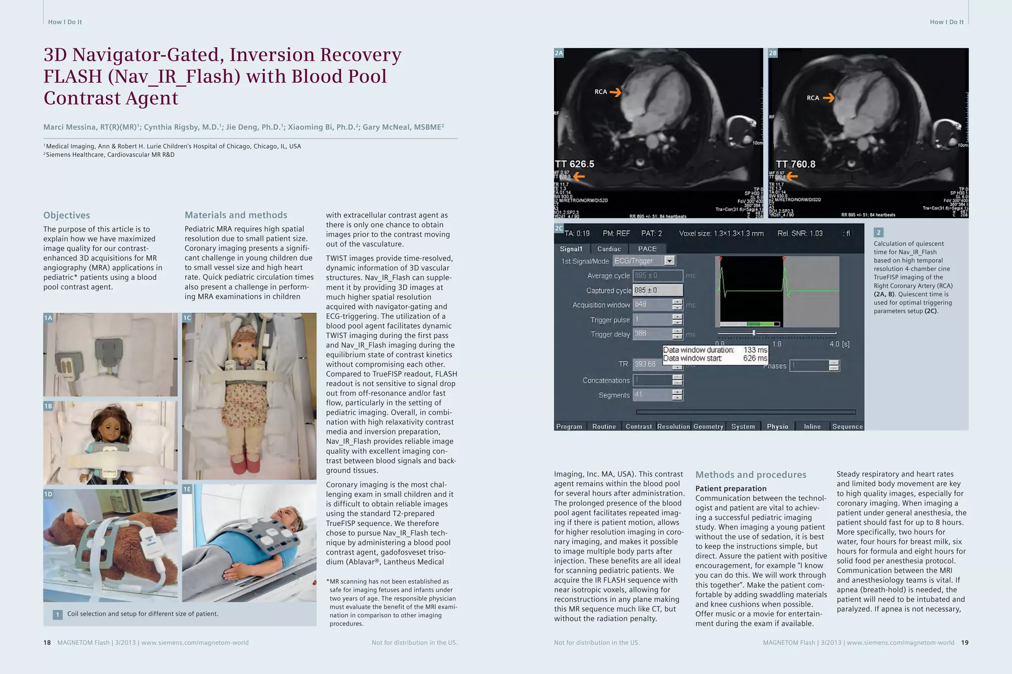
time for Nav_IR_Flash.
4. Ablavar administration
5. Coronal dynamic TWIST imaging
(temporal resolution 2.5 s/frame)
6. 3D Nav_IR_Flash_TI_260_Coronal/
Axial Oblique. This sequence is
scanned after the single dose injec-tion
on TWIST sequence. Figure 2C
shows the optimal trigger parameter
adjustments to acquire data
during the quiescent period.
Imaging can be performed at 3T.
Alteration in the protocol for 3T imag-ing
includes changing the inversion-recovery
time (TI) to 350 ms and flip
angle to 15 degrees.
Setting up the Nav_IR_Flash
sequence:
A. Plan from all 3 plane breath-hold
localizers
B. The Nav_IR_Flash sequence can be
converted from the T2-prepared
TrueFISP sequence by following the
parameters in Table 1.
C. In the Physio tab begin with click-ing
on capture cycle, then adjust
the number of segments to reach
the desired data window duration
time, and then adjust the trigger
delay to reach the desired data
window start time. Hover over the
trigger delay with cursor to see the
changes in the tooltips popup. For
example, if the quiet period of the
cardiac cycle (from the high resolu-tion
free breathing 4-chamber cine
image) is from TT 626 to TT 759,
then the data window start time
should be set to 626 and the data
window duration should be set to
133 (Fig. 2C).
D. Place the intersection of the cross-pair
navigators in the middle of the
dome of the liver as viewed from
the axial localizer (Fig. 3A). Then
right-click, perpendicular from the
axial image to find the navigator
on the corresponding sagittal and
coronal planes to verify its optimal
location centered at the level of
the diaphragm (Figs. 3B, C). Work-ing
on the axial plane, one can
slightly rotate the oblique navigator
away from the heart if it crosses
anatomy; however must not rotate
the orthogonal navigator (aligned
in anterior-posterior direction).
‘Couple graphics’ should be ‘off’ for
the dual navigator set up.
E. Before starting the scan, first run
the sequence in scout mode, check
the ‘Scout mode’ box in Physio-
PACE card (Fig. 3G). Open the Inline
Display window during the scout
mode to get the position histo-gram,
‘mode number’ (Figs. 3D, E).
Next, apply the mode number into
the ‘search position (red)’ and
uncheck the scout mode to run the
full scan. When viewing the navi-gator
signal within the Inline Dis-play
window, the green bar (Accept
3A 3B 3C
3D 3E 3F
Cross-pair navigator positioning (3A–C). Navigator scout (3D) gives position histogram for ‘Mode number’ (3E) calculation,
to determine the ‘search postion (red)’ for optimal navigator waveform during Nav_IR_Flash acquistion (3F).
3
3G
20 MAGNETOM Flash | 3/2013 | www.siemens.com/magnetom-world Not for distribution in the US. Not for distribution in the US. MAGNETOM Flash | 3/2013 | www.siemens.com/magnetom-world 21](https://image.slidesharecdn.com/magnetomflash53angiography-00934901-140821154918-phpapp02/75/MR-Angiography-Edition-Issue-53-11-2048.jpg)


![Technology MR Angiography MR Angiography Technology
Heart
Beat #
1
2
⋅
⋅
⋅
Outer Loop
(Slice-Enc.,kz)
Inner Loop
(Phase-Enc., ky)
Arterial window
Time
arterial
phase
venous
phase
Trigger
Delay
Inner Loop 1
Wait Time
Trigger
Delay
Inner Loop 2
Wait Time
Heart Beat #1 Heart Beat #2
• • •
The conventional approach to ECG-gated CE-MRA. In each heartbeat, all phase-encoding steps of a single slice-encoding line are
acquired. The TTC can be matched with the contrast timing since each triggered shot is acquired in linear order in slice direction.
2
ECG
2
of the acquisition. Furthermore, the
conventional gated CE-MRA technique
cannot reduce scan time by taking
advantage of parallel acquisition tech-nique
(iPAT) and partial Fourier in
phase encoding direction; if either of
these parameters is modified, the
total scan time remains the same since
conventional CE-MRA only a single
complete inner loop is played out per
heartbeat, regardless of its duration.
Moreover, the unpredictable nature
of the ECG-triggering adds some
uncertainty to the gated CE-MRA
method. While the sequence assumes
a steady R-R interval and uses a fixed
acquisition window, due to physiolog-ical
irregularities (the R-R interval can
vary during a breath-hold [5]) and
mechanical imperfections (ECG detec-tion
device can fail), trigger events
can be either detected too early or
too late to substantially increase the
scan time. The CE-MRA sequence has
a strict timing requirement with the
contrast arrival, and any deviation from
this may result in a contrast washout
with missed optimal timing.
This paper highlights recent advance-ments
in the ECG-gated CE-MRA
approach* that address these short-comings.
With these advancements,
high-resolution, full coverage ECG-gated
CE-MRA exams can be realized
within a single breath-hold.
* The sequence is currently under develop-ment
and is available as a work-in-progress
package (#691B for VB17A and #791 for
VD11D/13A); it is not for the sale in the US
and other countries. Its future availability
cannot be guaranteed.
Flexible trigger
segmentation
To improve the efficiency of the rigid
trigger segmentation in conventional
gated CE-MRA, we propose a flexible
approach (Fig. 3). Here, the inner
loop is not restricted to a single dimen-sion
in k-space. The points that are
sampled within the individual triggered
segments are determined with a fuzzy
pseudo-random algorithm. As a result,
the size and shape of the triggered
segments are no longer restricted.
In addition, the flexible triggered
segmentation can freely adjust the
acquisition order, both within and
in between triggered segments.
Not for distribution in the US. MAGNETOM Flash | 3/2013 | www.siemens.com/magnetom-world 33
Advancements in the ECG-Gated
Contrast-Enhanced MR Angiography
Yutaka Natsuaki, Ph.D.1; Randall Kroeker, Ph.D.1; Gerhard Laub, Ph.D.1; Peter Schmitt2; J. Paul Finn, M.D.3
1 Siemens Healthcare, CA, USA
2 Siemens AG, Healthcare Sector, Imaging & Therapy Division, Erlangen, Germany
3 Diagnostic Cardiovascular Imaging, Department of Radiology, David Geffen School of Medicine at UCLA, CA, USA
phase, where the cardiac motions
are most prominent. With proper
contrast
injection timing, the arterial
window can still be matched with the
center of the k-space in the outer
loop (i.e. slice encoding) direction.
With this scheme, the total scan time
corresponds to the average R-R inter-val
multiplied by the total number
of slice encoding steps.
Non-Gated
CE-MRA
Gated
CE-MRA
Time To Center (TTC)
Time To Center (TTC)
The major drawback of this conven-tional
acquisition inefficiency. A typical high-resolution
less than 200 phase encode steps in
ky direction. Hence, the data acquisi-tion
much shorter than the average R-R
interval, which reduces the efficiency
k=0
k=0
gated CE-MRA approach is its
non-gated CE-MRA proto-col
uses short TR times of 2.7 ms and
window during each heartbeat is
k
k
Non-gated CE-MRA vs. gated CE-MRA. Darker purple color bar represents the outer
k-space in both phase (ky) and slice (kz) encoding steps, and the lighter purple repre-sents
the inner k-space. The center of both phase and slice encoding steps (ky=0,
kz=0) is represented by k=0. Typically in CE-MRA, the contrast arrival timing is matched
with the center acquisition of the phase and slice encoding steps (i.e. considering
the time-to-center, TTC) for the optimal image contrast. For non-gated CE-MRA, the
data is acquired in a single continuous delayed centric trajectory, where phase and
slice encoding steps start from the outer k-space, then acquire inner k-space & k=0,
and finally the rest of the outerk-space to complete the scan. For the gated CE-MRA,
the acquisition is segmented (e.g. Fig. 2) and acquired in sync with the
ECG-triggering.
ECG
1
Introduction
For most of the current contrast-enhanced
MR angiography (CE-MRA)
examinations, the acquisition is
optimized
for the image contrast
enhancement by matching the con-trast
arrival timing with the acquisi-tion
of the central phase encoding
steps (i.e. time-to-center, TTC) [1].
The total scan time is kept short within
a breath-hold length (less than 25 s)
to suppress bulk breathing motion.
Typically, the CE-MRA data are acquired
without ECG-gating in a single
contin-uous
delayed centric trajectory (Fig. 1,
non-gated CE-MRA). While, for most
purposes, this approach is entirely
satisfactory, in CE-MRA of the thorax
the cardiac chambers and ventricular
outflow vessels can be delineated
with a certain degree of blurring with
non-gated acquisition. To address this
limitation, CE-MRA can be acquired
with ECG gating, whereby the seg-mented
data acquisition is synchro-nized
with the cardiac cycle [2, 3, 4]
(Fig. 1, gated CE-MRA).
The current product version of the
CE-
MRA sequence (fl3d_ce) supports
ECG gating with a rigid trigger seg-mentation
(Fig. 2, conventional gated
CE-MRA). For every trigger pulse, the
conventional gated CE-MRA acquires
all phase encoding steps for a single
value of the slice encoding gradient.
The acquisition is then repeated in
linear order for all slice encoding val-ues.
With a suitable trigger delay (TD),
the center of k-space in the inner loop
(i.e. phase-encoding) direction (ky = 0)
can be acquired outside of the sys-tolic
1
32 MAGNETOM Flash | 3/2013 | www.siemens.com/magnetom-world Not for distribution in the US.](https://image.slidesharecdn.com/magnetomflash53angiography-00934901-140821154918-phpapp02/75/MR-Angiography-Edition-Issue-53-17-2048.jpg)


![How I Do It How I Do It
Contrast-Enhanced MRA
in Practice: Tips and Caveats
Sarah N Khan, M.D.1; Yutaka Natsuaki, Ph.D.2; Wenchao Tao1, M.S.; Gerhard Laub, Ph.D.2; J. Paul Finn, M.D.1
1 Diagnostic Cardiovascular Imaging, Department of Radiology, David Geffen School of Medicine at UCLA, CA, USA
2 Siemens Healthcare, CA, USA
Introduction
At UCLA, we perform contrast-enhanced
MR angiography (CE-MRA)
in adults and children* of all ages,
covering most vascular territories.
In this short article, we will consider
thoracic and abdominal applications,
although similar principles apply
also to carotid and extremity MRA.
In some patients, CE-MRA is performed
as a stand-alone procedure and in
other cases it is combined with cardiac
MRI, brain MRI or abdominal MRI.
In all cases, some common rules and
guidelines apply in the setup and
execution
of the studies.
Although several non-contrast MRA
techniques exist and continue to
undergo development, CE-MRA is
generally faster, less flow-dependent
and more reliable than its non-con-trast
enhanced counterparts.
First, it is important to realize that
CE-
MRA is a procedure, not just a
pulse sequence, and each step should
be planned. A high performance 3D
pulse sequence is a prerequisite, but
on its own it is insufficient. For first
pass imaging, accurate timing of the
contrast bolus is crucial and in all
cases it is essential to avoid patient
motion artifact [1-15]. If we mistime
the bolus or the patient moves during
the acquisition, the study will be
degraded or non-diagnostic, no matter
how good the contrast agent or sys-tem
hardware.
At the time of writing, the U.S.
Food and Drug Administration (FDA)
has approved the usage of two gado-linium
based contrast agents for
vascular
imaging applications with
MR. These are gadofosveset (‘Ablavar’,
Lantheus Medical) and Gd BOPTA
(‘Multihance’, Bracco Diagnostics)
frequently than the peripheral por-tion
and data from neighboring
peripheral k-space sets are shared.
A detailed consideration of TWIST
parameters is beyond the scope of
this work, but we will simply state
that in all of our CE-MRA studies, we
use TWIST with very low dose Gd as
a timing run for the high-resolution
CE-MRA acquisition and sometimes
we acquire an additional breath-held,
low dose TWIST between the timing
run and the main Gd injection for the
high resolution study.
Based on the TWIST timing run, we
can read off the time it takes for the
test bolus to reach an early peak in
the vessel of interest (e.g. aorta). We
will then use this time as the starting
time for the high-resolution acquisi-tion
with infusion of the main con-trast
bolus. As mentioned above, the
center of k-space within the high-res-olution
(20 second) acquisition can
be positioned freely by the user, using
the TTC parameter in the exam card.
Some principles guide our choice of
the TTC.
1. The contrast bolus must be in the
vessels of interest when we acquire
the center of k-space. If the center
of k-space is acquired before the
bolus arrives, we will fail to show
the major vessels and the study will
be non-diagnostic. This is a worst-case
scenario and is sometimes
referred to as ‘high pass filtering’
because the low spatial frequencies
are compromised and only the high
spatial frequencies are ‘passed
through’. Without low spatial fre-quency
information, the study is
useless.
2. The contrast bolus should persist
for long enough in the vessels of
interest to encompass not just the
center of k-space, but the periph-ery
also. If the bolus is too short
and covers only the center of
k-space, large vessels may appear
bright but the images will be
blurred and fine edge detail will
be compromised. This is sometimes
referred to as ‘low pass filtering’
because the high spatial frequencies
are compromised and only the
low spatial frequencies are ‘passed
through’.
Contrast agent ‘preparation’ –
we dilute! Why?
In 2007, the association between
nephrogenic systemic fibrosis (NSF)
and gadolinium administration in
patients with renal failure was discov-ered
[18-21]. It became clear that the
high doses of Gd used routinely for
CE-MRA were particularly problem-atic,
and as a community we imple-mented
immediate and sometimes
draconian restrictions and dose reduc-tions
in the use of Gd. As a result,
NSF has virtually disappeared and no
new cases have been confirmed in
the past several years.
In the process of evaluating dose
reduction regimens for CE-MRA, we
were faced with some issues of imple-mentation.
The good news is that it
has proved feasible to reduce the dose
of Gd by a factor of 3-4 at 3T and of
2 at 1.5T, relative to what we used to
use in the past. So instead of using
double or triple dose (0.2–0.3 mmol/kg)
extracellular contrast agents, we can
still get very good results with single
dose or half-dose (0.05–0.1 mmol/kg)
[22]. The challenge is how to admin-ister
the lower dose while maintaining
the desired time course for the con-trast
bolus. So, for example, if we used
to use 30 ml of undiluted Gd over
15 seconds (injected at 2 ml/s) for
an average adult patient at 3T, we
might now want to use a quarter of
that dose (7.5 ml). If we inject at
2 ml/s, the entire amount is infused
in 3.5 seconds and we get a very
short peak. This will very likely result
in the ‘low pass filtering’ effect we
described above. If we extend the
infusion period to our 15 second target
by injecting at 0.5 ml/s, timing
may become unreliable for first pass
imaging because in some patients
the small volume of contrast may get
held up in the veins of the thoracic
inlet. An approach we have found
very reliable is to dilute the Gd back
up to the original volume (30 ml) and
inject the dilute solution at the origi-nal
rate (2 ml/s). The shape of the
contrast bolus will be exactly as it was
with the full strength Gd, but the
peak concentration will be propor-tionately
lower. Experience and theo-retical
considerations confirm that
the reduction in signal-to-noise ratio
3. We have found that a default
TTC of 6 seconds results in reliable
CE-MRA in most cases. Six seconds
is a typical value for contrast to
move from the arterial inflow to
the venous outflow of organs such
as brain, lungs and kidneys, so the
early peak of the arterial signal and
the center of k-space occur prior
to the venous peak. In children or in
cases where rapid venous enhance-ment
occurs on the timing run,
it may be appropriate to shorten
the TTC accordingly.
For many years, we have known that
for a 20 second acquisition, a contrast
infusion duration of about 15 seconds
will provide a wide enough bolus
plateau
to encompass all of k-space
adequately. For an adult, this has
typically
meant that we inject about
30 ml of contrast solution at 2 ml
per second, for a 15 second infusion
period. We would like the center of
k-space to occur during the early por-tion
of the plateau and we would like
to be acquiring only the peripheral
portions of k-space by the time the
veins fill. This means that we have
a high, fairly uniform concentration
of contrast in the arteries throughout
the acquisition (we ‘pass through’
both low and high spatial frequencies
for the arteries), while we effectively
have engineered high spatial fre-quency
filtering of the veins. In this
way, the arteries appear bright and
well defined while the veins are dark
in the center and only their edges are
seen. What we have described is an
ideal situation, but it can be made to
happen pretty routinely with proper
timing. If, however, there is substantial
contrast in the veins by the time we
acquire the center of k-space, we will
see both arteries and veins with a
similar intensity. Depending on the ter-ritory
and clinical question, this may
or may not be a big deal. In any case,
if our timing is not ideal, better to err
on the side of being a bit late than
too early – better to see arteries and
veins than neither arteries nor veins!
* MR scanning has not been established as
safe for imaging fetuses and infants under
two years of age. The responsible physician
must evaluate the benefit of the MRI exam-ination
in comparison to other imaging
procedures.
[16, 17]. The indication for Ablavar
is to evaluate aortoiliac occlusive
disease
(AIOD) in adults with known
or suspected peripheral vascular dis-ease,
and Multihance is to evaluate
adults with known or suspected renal
or aorto-ilio-femoral occlusive vascu-lar
disease. All other cardiovascular
indications with these agents are off
label (performed at the discretion
of the physician) and all cardiovascu-lar
indications with all other agents
are off label.
Although similar physical principles
apply when imaging adults and
children,
there are practicalities of
scale and logistics which make it use-ful
to consider them separately.
Prior to scanning, adult patients are
deemed suitable if they are alert and
co-operative and have no contraindi-cation
to gadolinium. Common indi-cations
for imaging the thoracic arter-ies
include evaluation of aortic
aneurysm, coarctation, dissection,
aortic valve disease and vasculitis, as
well as assessment for thoracic outlet
syndrome. Equipment setup requires
ECG leads for monitoring, IV place-ment
for contrast injection, and typi-cally
two body array coils.
In our experience, adult patients
can typically manage a comfortable
breath-hold of around 20 seconds.
Some can do more and some less, but
we will use this as our typical acquisi-tion
period for a high resolution,
contrast-
enhanced study. Both X-ray
CT angiography (CTA) and CE-MRA
depend on a timed contrast injection
to highlight the enhancing lumen.
However, whereas the signal with CTA
depends in a fairly straightforward
way on how well the vessels are opaci-fied
at the instant the slices are being
irradiated, CE-MRA uses spatial gradi-ents
to encode the signal and in the
process it traverses k-space. Over the
course of the 20 second (or there-abouts)
acquisition, k-space is tra-versed
at a fairly uniform speed, but
in a non-linear way. The center of
k-space encodes the bulk of the
image contrast and should be timed
always to occur when the contrast
bolus is in the vessels of interest. The
time, in seconds from the start of the
acquisition to the center of k-space
can be chosen freely by the user,
using the TTC parameter in the exam
card. Ideally, all of the k-space data
(not just the center) will be acquired
when the vessels contain the bolus,
but if the center is acquired before
the bolus arrives, only edges or small
vessels will be enhanced and the
study will be non-diagnostic (see
‘point 1’ below). If, on the other hand,
the center of k-space is acquired after
the veins enhance, these will appear
comparably bright to the arteries.
Ideal timing would position the cen-ter
of k-space at the early peak of
arterial enhancement, before the
veins enhance. It should be noted,
however, that in cases of abnormally
rapid venous filling, it may not be
possible to isolate the arterial phase
with a single, long high resolution
acquisition, and time resolved tech-niques
may be appropriate for this
purpose.
As an aside, time-resolved tech-niques,
such as TWIST, acquire mul-tiple
3D data sets sequentially, but
k-space is not sampled uniformly.
In order to increase the temporal
resolution, the central portion (e.g.
10–20%) of k-space is acquired more
40 MAGNETOM Flash | 3/2013 | www.siemens.com/magnetom-world Not for distribution in the US. Not for distribution in the US. MAGNETOM Flash | 3/2013 | www.siemens.com/magnetom-world 41](https://image.slidesharecdn.com/magnetomflash53angiography-00934901-140821154918-phpapp02/75/MR-Angiography-Edition-Issue-53-21-2048.jpg)
![How I Do It How I Do It
(SNR) due to the reduced peak con-centration
is much less than reduction
in contrast dose and the image qual-ity
holds up well.
In the examples that follow, we illus-trate
parameters and contrast dosages
and formulations in both adults and
children, based on the principles out-lined
above. More cases, together with
movie files and detailed parameters,
are available on the UCLA Cardiovas-cular
Imaging Gallery [23].
Thoraco-abdominal
CE-MRA in adults
With appropriate dilution, the contrast
volumes can be made identical at
1.5T and 3T, such that the injection
rates and volumes are the same at
both field strengths, even though the
concentration and dose of Gd is
lower at 3T.
With reference to the dilute solution,
as a general rule, we perform a sagittal
timing TWIST acquisition during free
breathing with injection of 3 ml at
a rate of 2 ml/s. Then we perform
breath-held coronal time TWIST with
injection of 7 ml at a rate of 3 ml/s.
Finally, we perform coronal high
resolution MRA with injection of
30 ml at a rate of 2 ml/s.
The cases below will illustrate these
principles. The actual doses and
dilution factors may differ slightly
from the sample schemes outlined
above, but in all cases they will be
approximately the same.
Note the immediate enhancement
of the right renal AVM with direct
shunting from the lower pole artery
(arrows in figures 2A and 2B) to
the grossly enlarged veins (arrows in
figures
2C and 2D).
2A 2B
2C 2D
2 Coronal breath-held TWIST; full thickness MIP reconstruction.
1A 1B 58-year-old female in good general
health; incidental finding of renal
arteriovenous malformation. She
denied symptoms of hematuria, flank
pain, dyspnea and did not have any
signs of pelvic congestion syndrome.
CE-MRA was performed to character-ize
the vascular malformation prior to
possible embolization therapy.
Scanner 3T MAGNETOM Trio,
A Tim System
Agent Multihance. 15 ml native
formulation of Multihance
was diluted to 45 ml with
normal saline.
Repetition time (TR) 2.0 ms
Echo time (TE) 0.9 ms
Flip angle 18 degrees
Bandwidth 1015 Hz/pixel
FOV 281 × 500
Matrix 202 × 488
Slice thickness 6 mm
Grappa acceleration
factor 2
Temporal resolution 0.9 s
4 ml one third
strength Multihance
at 2 ml/s
Case A: Adult renal arteriovenous fistula
1C 1D
1 Oblique sagittal TWIST timing; full thickness MIP reconstruction.
TR 2.0 ms
TE 0.9 ms
Flip angle 16 degrees
Bandwidth 751 Hz/pixel
FOV 312 x 500
Matrix 211 x 512
Slice thickness 4 mm
Grappa acceleration
factor 3
Temporal resolution 1.0 s
11 ml one third
strength Multihance
at 3 ml/s
Peak aortic enhancement occurs at
15 seconds and this is the time delay
chosen to begin the high-resolution
CE-MRA acquisition.
42 MAGNETOM Flash | 3/2013 | www.siemens.com/magnetom-world Not for distribution in the US. Not for distribution in the US. MAGNETOM Flash | 3/2013 | www.siemens.com/magnetom-world 43](https://image.slidesharecdn.com/magnetomflash53angiography-00934901-140821154918-phpapp02/75/MR-Angiography-Edition-Issue-53-22-2048.jpg)


![How I Do It
16 http://www.ablavar.com/home.html
17 http://imaging.bracco.com/us-en/
products-and-solutions/contrast-media/
multihance
18 Reiter T, Ritter O, Prince MR, Nordbeck P,
Wanner C, Nagel E, Bauer WR. Minimizing
risk of nephrogenic systemic fibrosis in
cardiovascular magnetic resonance. J
Cardiovasc Magn Reson. 2012 May
20;14:31. doi: 10.1186/1532-429X-
14-31. Review. PubMed PMID: 22607376;
PubMed Central PMCID: PMC3409035.
19 Zou Z, Zhang HL, Roditi GH, Leiner T,
Kucharczyk W, Prince MR. Nephrogenic
systemic fibrosis: review of 370 biopsy-confirmed
cases. JACC Cardiovasc
Imaging. 2011 Nov;4(11):1206-16. doi:
10.1016/j.jcmg.2011.08.013. Review.
PubMed PMID: 22093272.
20 Prince MR, Zhang HL, Prowda JC,
Grossman ME, Silvers DN. Nephrogenic
systemic fibrosis and its impact on
abdominal imaging. Radiographics. 2009
Oct;29(6):1565-74. doi: 10.1148/
rg.296095517. Review. PubMed PMID:
19959508.
21 Prince MR, Zhang HL, Roditi GH, Leiner T,
Kucharczyk W. Risk factors for NSF: a
literature review. J Magn Reson Imaging.
2009 Dec;30(6):1298-308. doi: 10.1002/
jmri.21973. Review. PubMed PMID:
19937930.
22 Nael K, Moriarty JM, Finn JP. Low dose
CE-MRA. Eur J Radiol. 2011 Oct;80(1):
2-8. doi: 10.1016/j.ejrad.2011.01.092.
Epub 2011 Apr 1. Review. PubMed PMID:
21458187.
23 http://www.radnet.ucla.edu/safaridemos/
showcase/gallery
Contact
J. Paul Finn, M.D.
Diagnostic Cardiovascular
Imaging
Department of Radiology
David Geffen School of
Medicine at UCLA
10833 Le Conte Ave.
Los Angeles, CA 90095
USA
pfinn@mednet.ucla.edu
References
1 Nael K, Krishnam M, Nael A, Ton A,
Ruehm SG, Finn JP. Peripheral contrast-enhanced
MR angiography at 3.0T,
improved spatial resolution and low
dose contrast: initial clinical experience.
Eur Radiol. 2008 Dec;18(12):2893-900.
doi: 10.1007/s00330-008-1074-y. Epub
2008 Jul 11. PubMed PMID: 18618122.
2 Kramer JH, Grist TM. Peripheral MR
Angiography. Magn Reson Imaging Clin
N Am. 2012 Nov;20(4):761-76. doi:
10.1016/j.mric.2012.08.002. Epub 2012
Sep 25. Review. PubMed PMID:
23088949.
3 Krishnam MS, Tomasian A, Lohan DG,
Tran L, Finn JP, Ruehm SG.
Low-dose, time-resolved, contrast-enhanced
3D MR angiography in cardiac
and vascular diseases: correlation to
high spatial resolution 3D contrast-enhanced
MRA. Clin Radiol. 2008
Jul;63(7):744-55. doi: 10.1016/j.
crad.2008.01.001. Epub 2008 Mar 28.
PubMed PMID: 18555032.
4 Pasqua AD, Barcudi S, Leonardi B,
Clemente D, Colajacomo M, Sanders SP.
Comparison of contrast and noncontrast
magnetic resonance angiography for
quantitative analysis of thoracic arteries
in young patients with congenital heart
defects. Ann Pediatr Cardiol. 2011
Jan;4(1):36-40. doi: 10.4103/0974-
2069.79621. PubMed PMID: 21677803;
PubMed Central PMCID: PMC3104530.
5 Nael K, Ruehm SG, Michaely HJ, Saleh R,
Lee M, Laub G, Finn JP. Multistation
whole-body high-spatial-resolution MR
angiography using a 32-channel MR
system. AJR Am J Roentgenol. 2007
Feb;188(2):529-39. PubMed PMID:
17242265.
6 Fenchel M, Saleh R, Dinh H, Lee MH,
Nael K, Krishnam M, Ruehm SG, Miller S,
Child J, Finn JP. Time-resolved 3D
contrast-enhanced MR Angiography in
Adult Congenital Heart Disease.
Radiology 2007 Aug;244(2):399-410.
7 Kim CY, Merkle EM. Time-resolved MR
angiography of the central veins of
the chest. AJR Am J Roentgenol. 2008
Nov;191(5):1581-8. doi: 10.2214/
AJR.08.1027. PubMed PMID: 18941105.
8 Nael K, Saleh R, Nyborg GK, Fonseca CG,
Weinmann HJ, Laub G, Finn JP. Pulmonary
MR perfusion at 3.0 Tesla using a blood
pool contrast agent: Initial results in
a swine model. J Magn Reson Imaging.
2007 Jan;25(1):66-72. PubMed PMID:
17154181.
9 Fenchel M, Nael K, Deshpande VS, Finn
JP, Kramer U, Miller S, Ruehm S, Laub G.
Renal magnetic resonance angiography
at 3.0 Tesla using a 32-element phased-array
coil system and parallel imaging in
2 directions. Invest Radiol. 2006
Sep;41(9):697-703. PubMed PMID:
16896305.
10 Lohan DG, Krishnam M, Tomasian A,
Saleh R, Finn JP. Time-resolved MR
angiography of the thorax. Magn Reson
Imaging Clin N Am. 2008
May;16(2):235-48, viii. doi: 10.1016/j.
mric.2008.02.015. Review. PubMed
PMID: 18474329.
11 Nael K, Fenchel MC, Kramer U, Finn JP,
Ruehm SG. Whole-body contrast-enhanced
magnetic resonance angiog-raphy:
new advances at 3.0 T. Top Magn
Reson Imaging. 2007 Apr;18(2):127-34.
Review. Erratum in: Top Magn Reson
Imaging. 2007 Aug;18(4):316. Gruehm,
Stefan [corrected to Ruehm, Stefan G].
PubMed PMID: 17621226.
12 Young PM, McGee KP, Pieper MS,
Binkovitz LA, Matsumoto JM, Kolbe AB,
Foley TA, Julsrud PR. Tips and tricks for
MR angiography of pediatric and adult
congenital cardiovascular diseases.
AJR Am J Roentgenol. 2013 May;200(5):
980-8. doi: 10.2214/AJR.12.9632.
PubMed PMID: 23617479.
13 Nael K, Saleh R, Lee M, McNamara T,
Godinez SR, Laub G, Finn JP, Ruehm SG.
High-spatial-resolution contrast-enhanced
MR angiography of abdominal arteries
with parallel acquisition at 3.0 T: initial
experience in 32 patients. AJR Am J
Roentgenol. 2006 Jul;187(1):W77-85.
PubMed PMID: 16794143.
14 Nael K, Laub G, Finn JP. Three-dimensional
contrast-enhanced MR angiography of
the thoraco-abdominal vessels. Magn
Reson Imaging Clin N Am. 2005 May;
13(2):359-80. Review. PubMed PMID:
15935317.
15 Michaely HJ, Nael K, Schoenberg SO, Finn
JP, Laub G, Reiser MF, Ruehm SG. The
feasibility of spatial high-resolution
magnetic resonance angiography (MRA)
of the renal arteries at 3.0 T. Rofo.
2005 Jun;177(6):800-4. PubMed PMID:
15902628.
54 MAGNETOM Flash | 3/2013 | www.siemens.com/magnetom-world Not for distribution in the US.
Pediatric ImagHinogw C-lIi-ndioc-aitl
Battlefield Imaging,
Ringgold, USA;
Benedictus Hospital,
Tutzing, Germany;
Hong Kong Sanatorium &
Hospital, Happy Valley,
Hong Kong;
MR Bremen Mitte,
Bremen, Germany;
Siemens AG,
Healthcare Sector,
Erlangen, Germany;
Tateyama Hospital,
Tateyama, Japan;
University Hospital,
Essen, Germany;
University Hospital
Rechts der Isar,
Munich, Germany;
University Hospital UCLA,
Los Angeles, USA;
www.siemens.com/CMR
MR Angiography
2013 55
MAGNETOM Flash · 2/2011 · www.siemens.com/magnetom-world Get your
free copy
of the MR
Angiography
poster
Visit us at
www.siemens.com/
magnetom-world
Go to > Publications >
Subscriptions > MRI Poster
MR angiography is one of the most-performed
exams in Magnetic Resonance Imaging (MRI). MRI
offers not only visualization of vessel lumen like
conventional angiography, but also the possibility
to analyse the vessel walls. The Siemens application
syngo TWIST even enables dynamic angiographical
imaging, with very low dose of contrast. And, with
syngo NATIVE no contrast agent is used at all. With the
Siemens-unique continuous table move, syngo TimCT,
even a complete whole-body scan can be performed in
a matter of minutes.
Answers for life.
Order No. A91MR-1100-49X-7600 | Printed in Germany | CC 415 0412.5 | © 04.2012, Siemens AG](https://image.slidesharecdn.com/magnetomflash53angiography-00934901-140821154918-phpapp02/75/MR-Angiography-Edition-Issue-53-28-2048.jpg)


This document is an issue of MAGNETOM Flash magazine focused on MR angiography. It discusses several techniques for non-contrast MR angiography including flow-sensitive dephasing prepared 3D balanced steady-state free precession. This technique uses a flow-sensitive dephasing module to selectively depict arterial flow on subtraction of images acquired during systole and diastole. The document provides details on the principles, technical considerations including choice of gradients and flow sensitization strength, and clinical applications for imaging the lower legs, feet and hands. It demonstrates comparable diagnostic accuracy to contrast-enhanced MRA for evaluation of vascular disease.


