Downloaded 506 times
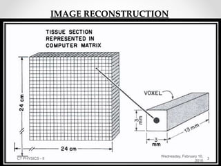
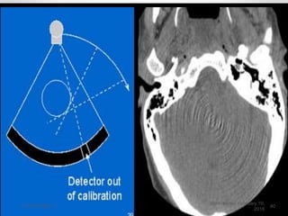

This document provides an overview of a lecture on CT physics - II. It discusses topics like image reconstruction algorithms including back projection, iterative methods, and analytical methods. It also covers Hounsfield units, image quality factors like noise, spatial resolution and contrast resolution. Additional sections describe applications of CT like 3D imaging, CT fluoroscopy, cardiac CT, CT angiography, and dual energy CT. Common artefacts seen on CT like motion artefacts, streak artefacts, beam hardening artefacts and ring artefacts are also summarized.


