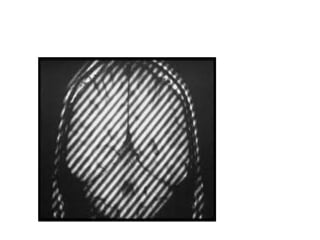
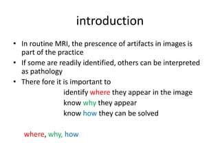
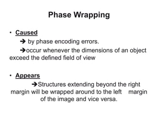
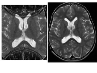
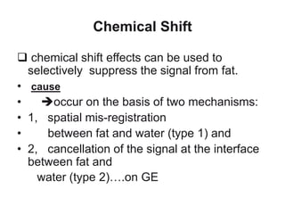
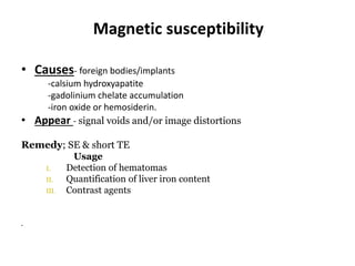
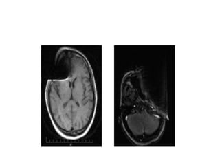
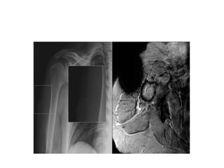
Artifacts in MRI
Dr. Henock.N ( r2)
moderator; Dr. Yirga
kidanu, Radiologist
 identification,
explanation and
solution
overview
• Introduction
• Artifacts encountered in mri
• conclusion
introduction
• In routine MRI, the prescence of artifacts in images is
part of the practice
• If some are readily identified, others can be interpreted
as pathology
• There fore it is important to
identify where they appear in the image
know why they appear
know how they can be solved
where, why, how
Brief why
 Hardware issues;
e.g power supply instability, calibration
 software issues;
e.g programming errors in the pulse sequence
 Physiological reasons;
e.g blood flow, respiration , peristalsis
 Physics;
e.g,magnetic susceptibility
How
• Some artifacts can be solved with the intervention of
the MR technician or MR physicist;
• But some of them have to be solved by an MR
engineer
• Therfore it is very important to learn where those
artifacts appear in the images in order to decide the
best cource of action
Motion artifact
• MRI is very sensitive to motion artifact since it takes time to
acquire the image using the conventional SE sequence.
• Also caused by – cardiac and respiratory movement,
peristalsis
- moving blood or csf.
• Eliminated by using different techniques.
1. Respiratory compression
2. Respiratory gating
3. Cardiac gating
4. Phase & frequency direction swap
Phase Wrapping
• Caused
 by phase encoding errors.
occur whenever the dimensions of an object
exceed the defined field of view
• Appears
Structures extending beyond the right
margin will be wrapped around to the left margin
of the image and vice versa.
Chemical Shift
 chemical shift effects can be used to
selectively suppress the signal from fat.
• cause
• occur on the basis of two mechanisms:
• 1, spatial mis-registration
• between fat and water (type 1) and
• 2, cancellation of the signal at the interface
between fat and
water (type 2)….on GE
remedy
• Use SE sequence
• Use fat suppression techniques
• Use wider reciever bandwidth
Usage
tissue characterization
diagonsing fatty pathologies
Truncation Artifacts
• Its other names are Ringing, Gibbs Or Spectacle
Leakage Artifacts.
 Cause
results from under - sampling of data (too few K space
lines filled) so that interfaces of high and low signal are
incorrectly represented on the image
 Appear
as semicircular or straight bright or dark lines
immediately adjacent to high contrast interfaces..i.e CSF
and spinal cord
(it can mimic syrinx)
 Eliminated
Increasing matrix size along the phase-encoding
direction
Gradient reorientation will displace the artifacts to
another portion of the image.
Magnetic susceptibility
• Causes- foreign bodies/implants
-calsium hydroxyapatite
-gadolinium chelate accumulation
-iron oxide or hemosiderin.
• Appear - signal voids and/or image distortions
Remedy; SE & short TE
Usage
I. Detection of hematomas
II. Quantification of liver iron content
III. Contrast agents
•
Magic angle
 Tendons and ligaments have a very short T2 relaxation time.
 But, when they are oriented in 55o to the z axis their signal
may increase and mimic pathology.
 Appear
 as a bright signal
EDDY ARTIFACT
• Caused
• By rapid on/off of the gradient coil  produce a small
current.
• Appears
As a signal drop in the margin of the image.
• Remedy
Shield gradient coils
Partial volume artifact
The signal intensity of different tissues and structures
that are located in the same voxel are averaged.
Remedy
use thinner slice thickness
Axial T1WI of the brain at exactly the same level. Second image shows 7th and 8th cranial nerves (arrow) but the first one merely depicts them.
The reason for this is the partial volume averaging. The first slice was taken at thickness of 10 mm while second slice was taken at 3 mm.
Zipper artifact
• Causes imperfectly closed room
• supportive equipments e.g pulsoximetry
• Appear : as a line of alternatively bright and dark pixels
running through the image in two ways,
• phase encoding direction
due to radio frequency noise and external effect
• frequency encoding direction
imperfect slice selection or inadequate radio frequency
pulse.
Crisscross or Herringbone Artifacts
• caused
due to a data processing or
reconstruction error.
• Appears
It is characterized by an obliquely oriented
stripe that is seen
throughout the image.
• Eliminated
reconstructing the image again.
Thank you!!!

MRI Artifact Radiology

  • 1.
    Artifacts in MRI Dr.Henock.N ( r2) moderator; Dr. Yirga kidanu, Radiologist
  • 2.
  • 3.
    overview • Introduction • Artifactsencountered in mri • conclusion
  • 4.
    introduction • In routineMRI, the prescence of artifacts in images is part of the practice • If some are readily identified, others can be interpreted as pathology • There fore it is important to identify where they appear in the image know why they appear know how they can be solved where, why, how
  • 5.
    Brief why  Hardwareissues; e.g power supply instability, calibration  software issues; e.g programming errors in the pulse sequence  Physiological reasons; e.g blood flow, respiration , peristalsis  Physics; e.g,magnetic susceptibility
  • 6.
    How • Some artifactscan be solved with the intervention of the MR technician or MR physicist; • But some of them have to be solved by an MR engineer • Therfore it is very important to learn where those artifacts appear in the images in order to decide the best cource of action
  • 7.
    Motion artifact • MRIis very sensitive to motion artifact since it takes time to acquire the image using the conventional SE sequence. • Also caused by – cardiac and respiratory movement, peristalsis - moving blood or csf.
  • 9.
    • Eliminated byusing different techniques. 1. Respiratory compression 2. Respiratory gating 3. Cardiac gating 4. Phase & frequency direction swap
  • 10.
    Phase Wrapping • Caused by phase encoding errors. occur whenever the dimensions of an object exceed the defined field of view • Appears Structures extending beyond the right margin will be wrapped around to the left margin of the image and vice versa.
  • 12.
    Chemical Shift  chemicalshift effects can be used to selectively suppress the signal from fat. • cause • occur on the basis of two mechanisms: • 1, spatial mis-registration • between fat and water (type 1) and • 2, cancellation of the signal at the interface between fat and water (type 2)….on GE
  • 14.
    remedy • Use SEsequence • Use fat suppression techniques • Use wider reciever bandwidth Usage tissue characterization diagonsing fatty pathologies
  • 15.
    Truncation Artifacts • Itsother names are Ringing, Gibbs Or Spectacle Leakage Artifacts.  Cause results from under - sampling of data (too few K space lines filled) so that interfaces of high and low signal are incorrectly represented on the image  Appear as semicircular or straight bright or dark lines immediately adjacent to high contrast interfaces..i.e CSF and spinal cord (it can mimic syrinx)
  • 17.
     Eliminated Increasing matrixsize along the phase-encoding direction Gradient reorientation will displace the artifacts to another portion of the image.
  • 18.
    Magnetic susceptibility • Causes-foreign bodies/implants -calsium hydroxyapatite -gadolinium chelate accumulation -iron oxide or hemosiderin. • Appear - signal voids and/or image distortions Remedy; SE & short TE Usage I. Detection of hematomas II. Quantification of liver iron content III. Contrast agents •
  • 21.
    Magic angle  Tendonsand ligaments have a very short T2 relaxation time.  But, when they are oriented in 55o to the z axis their signal may increase and mimic pathology.  Appear  as a bright signal
  • 23.
    EDDY ARTIFACT • Caused •By rapid on/off of the gradient coil  produce a small current. • Appears As a signal drop in the margin of the image. • Remedy Shield gradient coils
  • 25.
    Partial volume artifact Thesignal intensity of different tissues and structures that are located in the same voxel are averaged. Remedy use thinner slice thickness
  • 26.
    Axial T1WI ofthe brain at exactly the same level. Second image shows 7th and 8th cranial nerves (arrow) but the first one merely depicts them. The reason for this is the partial volume averaging. The first slice was taken at thickness of 10 mm while second slice was taken at 3 mm.
  • 27.
    Zipper artifact • Causesimperfectly closed room • supportive equipments e.g pulsoximetry • Appear : as a line of alternatively bright and dark pixels running through the image in two ways, • phase encoding direction due to radio frequency noise and external effect • frequency encoding direction imperfect slice selection or inadequate radio frequency pulse.
  • 29.
    Crisscross or HerringboneArtifacts • caused due to a data processing or reconstruction error. • Appears It is characterized by an obliquely oriented stripe that is seen throughout the image. • Eliminated reconstructing the image again.
  • 32.

Editor's Notes

  • #17 Truncation artifact. Sagittal fat-suppressed fast spin- echo T2-weighted image of the cervical spine shows a band of increased signal intensity within the spinal cord. This mimics a syrinx and is due to insufficient phase-encoding steps in the anterior-posterior direction.
  • #21 Fig. 15: This tiny piece of metal (square) visible on a shoulder x-ray caused the magnetic susceptibility artifact seen on the MR image (T2*). The loss of signal and image distortion caused by that metal piece significantly impairs our interpretation of the images.
  • #27 Axial T1WI of the brain at exactly the same level. Second image shows 7th and 8th cranial nerves (arrow) but the first one merely depicts them. The reason for this is the partial volume averaging. The first slice was taken at thickness of 10 mm while second slice was taken at 3 mm.