Download as PDF, PPTX
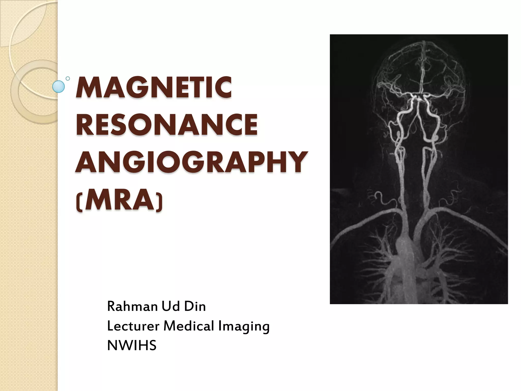
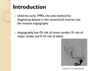
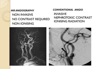

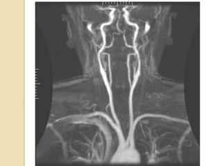
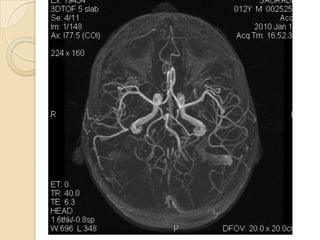
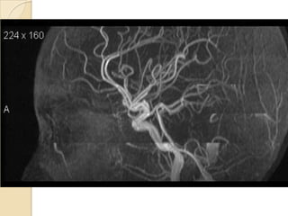
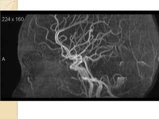
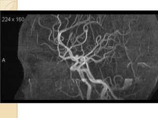
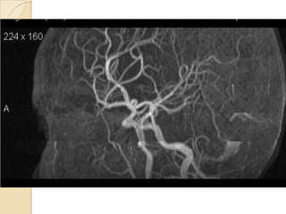
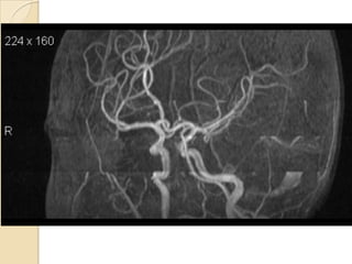
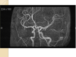
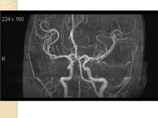
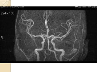
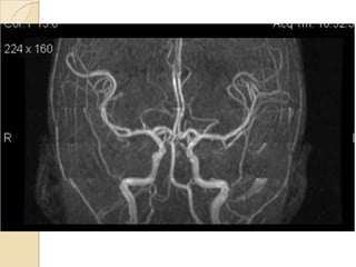
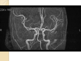
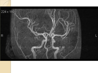
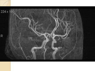
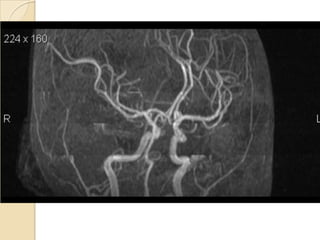
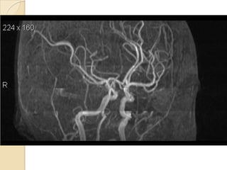
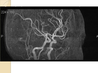
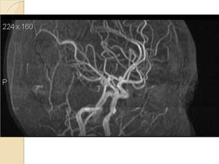
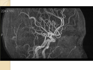
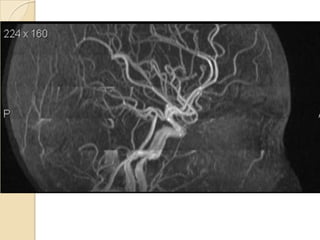
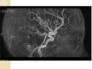


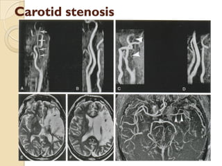
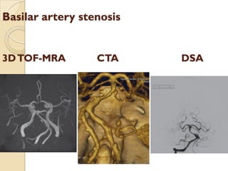
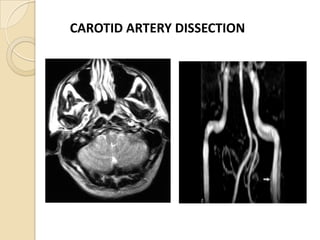


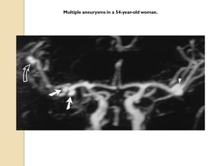
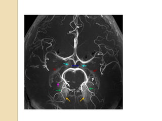
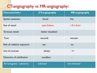

Magnetic Resonance Angiography (MRA) is a non-invasive imaging technique used to evaluate vascular conditions in the brain, offering lower risks compared to traditional angiography. It includes techniques like Time-of-Flight (TOF) and Phase Contrast (PC), each with unique advantages and applications in diagnosing stenoses, aneurysms, and arterial dissections. MRA is preferred for its ability to provide detailed images without requiring contrast agents or exposing patients to ionizing radiation.


