Downloaded 26 times


![40 Educational
Vascular permeability analysis
based on MR data
MR Permeability package on the IntelliSpace Portal calculates permeability based on MR data
Vascular permeability depends on tissue and its condition
Fast cell growth requires extra blood and nutrient supply and is often
characterized by angiogenesis (growth of extra blood vessels from
existing vessels). Angiogenesis is a process that occurs in tissue
growth and repair.
Angiogenesis is often accompanied by increased vascular permeability.
Vascular permeability is the ability of a blood vessel wall to allow molecules
to pass through. Permeability depends on tissue type and organ.
In a healthy brain the blood brain barrier (BBB) effectively separates
circulating blood from the extracellular fluid in the central nervous
system. This means that the vessel wall restricts diffusion of larger objects
like bacteria and certain molecules into the brain. Only small molecules
like O2, hormones and CO2 can pass into the tissue. Therefore, the
measured permeability in a healthy brain is very low, close to zero.
The vessels in other organs, for instance the prostate, are much more
permeable, with values larger than zero.
Acquisition and processing of MR data for calculating permeability
Based on MR data, the MR Permeability tool on IntelliSpace Portal can
be used to determine the leakage of contrast agent (gadolinium chelates)
into the extra-vascular, extracellular space (EES). The most important
use is currently in prostate and brain.
The MR scanning starts with two separate 3D T1-weighted scans with
different flip angles to determine the T1 relaxation time of the tissue.
Then, Dynamic Contrast Enhanced (DCE) imaging is performed with
high spatial and high temporal resolution [1].
The Permeability analysis tool will automatically combine the 3D
T1-weighted and DCE series to immediately provide permeability
results. An important choice for the calculation is the Arterial Input
Function (AIF) used to fit all results to the Tofts model [1]. The MR
Permeability package provides two ways to define the AIF: based on
the injection protocol or based on actual DCE data.
The MR Permeability tool calculates permeability maps, but it also
conveniently provides color maps that combine the quantitative results
with the source data and with anatomical data – typically T2-weighted
and diffusion images – always geometrically aligned with the original
DCE acquisition.
Permeability parameters
Based on the Tofts model [1], the MR Permeability tool provides maps
of the kinetic parameters Ktrans and Kep.
Ktrans describes the transfer of the diffusible tracer (contrast agent) into
the EES. This transfer will depend largely on the permeability, and also
on the flow of the blood plasma that carries the contrast agent.
Kep describes the efflux of the same tracer from the EES back to the
blood plasma. This efflux rate depends on permeability, but also on
the EES volume compared to the blood plasma volume: a tissue with
a small percentage of EES will have a relatively large vessel wall area
to enable the efflux.
Schematic representation of physiology related to flow
and permeability in blood vessels. Depending on the tissue
characteristics, some of the contrast agent leaks into the
extravascular extracellular space (EES). The MR contrast agent does
not enter the cells, but will wash in and out of the EES.
FieldStrength - I 40 ssue 49 - 2013/2](https://image.slidesharecdn.com/fieldstrengthissue492013-140821172744-phpapp01/85/FieldStrength-49-40-320.jpg)


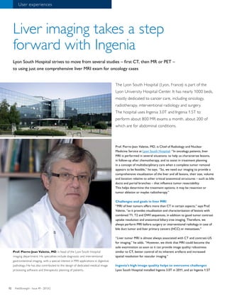
Dr. Punwani at University College London Hospital uses the Philips Ingenia 3.0T MRI for multi-parametric prostate and whole-body oncology exams. Multi-parametric MRI provides more information than standard anatomical imaging alone by including techniques like diffusion-weighted imaging, dynamic contrast-enhanced imaging, and spectroscopy. This additional data helps localize and characterize lesions, assisting in initial diagnosis and monitoring treatment effectiveness. The Ingenia's dS coils enable high-quality, whole-body multi-parametric MRI exams within a reasonable scan time.


