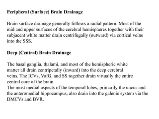
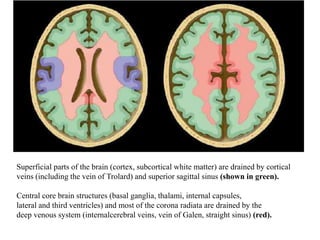
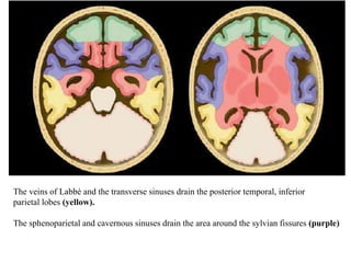
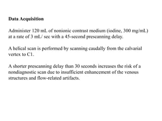
Superficial brain structures are drained by cortical veins and the superior sagittal sinus. Central brain structures drain into the deep venous system including the internal cerebral veins, vein of Galen, and straight sinus. The veins of Labbé and transverse sinuses drain the posterior temporal and inferior parietal lobes. MR venography and CT venography can assess the cerebral venous system, with each technique having advantages and disadvantages.
2. Normal Venous Anatomy
The intracranial venous system has two major components,
Dural venous sinuses.
Cerebral veins.
Dural Venous Sinuses
Dural venous sinuses are subdivided into
Anteroinferior group [cavernous sinus (CS), superior and inferior
petrosal sinuses (SPSs, IPSs), clival venous plexus (CVP), and
sphenoparietal sinus (SphPS)]
3. Posterosuperior group [superior sagittal sinus (SSS), inferior sagittal
sinus (ISS), straight sinus (SS), sinus confluence (torcular herophili),
transverse sinuses (TSs), sigmoid sinuses, and jugular bulbs]
Cerebral Veins
The cerebral veins are subdivided into three groups:
(1) Superficial ("cortical" or "external") veins
I. Superior Cortical Veins [eight and twelve unnamed superficial veins,
vein of Trolard]
II. Middle Cortical Veins [superficial middle cerebral vein (SMCV)]
III. Inferior Cortical Veins [deep middle cerebral vein (DMCV), basal
vein of Rosenthal (BVR)]
4. (2) Deep cerebral ("internal") veins, and
I. Medullary veins
II. Subependymal veins,
III. Deep paramedian veins
(3) Brainstem/posterior fossa veins.
I. Superior ("galenic") group [ precentral cerebellar vein (PCV), the
superior vermian vein, and the anterior pontomesencephalic vein
(APMV)]
II. Anterior (petrosal) group [petrosal vein (PV)]
III. Posterior group [inferior vermian veins]
7. Peripheral (Surface) Brain Drainage
Brain surface drainage generally follows a radial pattern. Most of the
mid and upper surfaces of the cerebral hemispheres together with their
subjacent white matter drain centrifugally (outward) via cortical veins
into the SSS.
Deep (Central) Brain Drainage
The basal ganglia, thalami, and most of the hemispheric white
matter all drain centripetally (inward) into the deep cerebral
veins. The ICVs, VofG, and SS together drain virtually the entire
central core of the brain.
The most medial aspects of the temporal lobes, primarily the uncus and
the anteromedial hippocampus, also drain into the galenic system via the
DMCVs and BVR.
8. Inferolateral (Perisylvian) Drainage
Parenchyma surrounding the sylvian (lateral cerebral) fissure consists of
the frontal, parietal, and temporal opercula plus the insula. This
perisylvian part of the brain drains via the SMCV into the SphPS and CS.
Posterolateral (Temporoparietal) Drainage
The posterior temporal lobes and inferolateral aspects of the parietal lobes
drain via the SPSs and anastomotic vein of Labbé into the TSs.
9. Superficial parts of the brain (cortex, subcortical white matter) are drained by cortical
veins (including the vein of Trolard) and superior sagittal sinus (shown in green).
Central core brain structures (basal ganglia, thalami, internal capsules,
lateral and third ventricles) and most of the corona radiata are drained by the
deep venous system (internalcerebral veins, vein of Galen, straight sinus) (red).
10. The veins of Labbé and the transverse sinuses drain the posterior temporal, inferior
parietal lobes (yellow).
The sphenoparietal and cavernous sinuses drain the area around the sylvian fissures (purple)
11. CT Venography
CT venography can be defined as a fast thin section volumetric helical
CT examination performed with a time-optimized bolus of contrast
medium in order to study the cerebral venous system.
To visualize the intracranial veins and sinuses, the examination
includes the region from the calvarial vertex down to the first vertebral
body.
Include the atlas (C1) in the study to ensure incorporation of the origin
of the jugular internal veins.
12. Data Acquisition
Administer 120 mL of nonionic contrast medium (iodine, 300 mg/mL)
at a rate of 3 mL/ sec with a 45-second prescanning delay.
A helical scan is performed by scanning caudally from the calvarial
vertex to C1.
A shorter prescanning delay than 30 seconds increases the risk of a
nondiagnostic scan due to insufficient enhancement of the venous
structures and flow-related artifacts.
13. Influence of the prescanning delay on sinus enhancement.
(a) Axial contrastenhanced CT image obtained with a prescanning delay of
25 seconds shows inadequate enhancement of the sigmoid sinuses and
jugular foramina.
(b) Axial contrast-enhanced CT image obtained with a prescanning delay of
45 seconds clearly shows a thrombus (arrow) in the right sigmoid sinus.
14. Postprocessing
Evaluation of venous structures includes multiplanar (sagittal, coronal
and oblique) reformatting on a 3D workstation, in which the loss of
information is minimized.
First, two-dimensional (2D) MPR images are used to visualize dural
venous sinuses and cerebral veins, with adequate window level and
width.
The source images are displayed with a window higher than or equal to
260 HU and a level of approximately 130 HU to clearly visualize the
cerebral veins and dural sinuses as separate from the adjacent bone of
the calvaria.
Second, 2D maximum intensity projection (MIP) series are created and
saved.
15. Optional reformations include 3D MIP and volume rendering display
algorithms, which typically require less than 5 minutes.
Further postprocessing with a 3D integral display algorithm is
performed in cases of cortical venous thrombosis and requires 10–15
minutes.
Model Preparation for 3D Display Algorithms
Postprocessing is performed with a 3D workstation. For reformation, a
graded subtraction is used to remove bone without deleting venous
structures.
The high attenuation of cortical bone of the skull is isolated
first (the mask) without including any veins.
The bone model (mask) is then subtracted from the main data set to
create a first-phase vascular model.
16. This model contains residual bone, which is similar in attenuation to
the vessels. The residual bone can be added to the mask through a
process called dilation.
Graded subtractions of the dilated bone mask from the vascular model
allow complete removal of the skull, typically after 2-pixel dilation of
the mask, without sacrificing vascular and soft-tissue detail for the
integral display algorithm.
Three-Dimensional Display Algorithms
The MIP algorithm projects intensity on the viewing screen that is the
brightest intensity in the 3D model volume along a ray perpendicular to
the viewing screen. This display technique enables one to visualize the
high-attenuation vessels through the low-attenuation brain.
17. Normal sinovenous anatomy.
Axial MIP CT image (a) and 3D volume-rendered image from CT venography
(oblique anterosuperior view) (b) show the internal cerebral veins (ICV),
basal veins of Rosenthal (BVR), vein of Galen (VOG), and straight sinus (StrS).
On the volume-rendered image, note the asymmetric appearance of the torcular
herophili (TH), which is formed by the union of the superior sagittal sinus (SSS),
straight sinus, and transverse sinuses (TS). The volume-rendered image also
shows the sigmoid sinus (SS) and superficial middle cerebral vein (SMCV).
18. Sagittal MIP CT image shows the
inferior sagittal sinus (ISS), as well as
the internal cerebral vein, superior
sagittal sinus, straight sinus, and vein
of Galen.
19. Normal sinovenous anatomy. Three dimensional integral image from CT
venography (lateral view) shows the anastomotic vein of Trolard (AVOT)
draining into the superior sagittal sinus (SSS), the anastomotic vein of
Labbe (AVOL) draining into the transverse sinus (TS), and the superficial
middle cerebral vein (SMCV).
20. MRV
MRV stands for magnetic resonance venography.
MRV is used to assess abnormalities in venous drainage of the brain .
2-dimensional (2D) time-of-flight (TOF) MR venography (MRV) and
3-dimensional (3D) phase-contrast (PC) are the technique commonly
used to assess the cerebral venous sinuses because they are easy to
perform and do not require contrast administration.
21. Time-of-flight (TOF)
This technique shows contrast between stationary tissues and
flowing blood by manipulating the magnitude of magnetization.
The magnitude of magnetization from the moving spins is very
large compared to the magnetization from the stationary spins
which is relatively small.
This leads to a large signal from moving blood spins and a
diminished signal from stationary tissue spins.
Time of flight (TOF) utilizes the longitudinal magnetization vector
for imaging.
22. Phase contrast (PC)
These techniques drive contrast between stationary tissues and flowing
blood by manipulating the phase of the magnetization.
The phase of the magnetization from the stationary spins is zero and
the phase of the magnetization from the moving spins is non-zero.
The phase is a measure of how far the magnetization process from the
time it is tipped into the transverse plane until the time it is detected.
A bipolar gradient pulse with equal magnitude and opposite direction
is used to diminish signal from the stationary tissue.
Phase contrast angiography (PCA) utilises the transverse
magnetization vector.
23. In phase difference images, the signal is linearly proportional to the
velocity of the spins. Fast moving spins give rise to a larger signal and
spins moving in one direction are assigned a bright signal and appear
white in the scan , whereas spins moving in the opposite direction are
assigned a dark signal and appear black in the scan.
Phase contrast methods are sensitive to a range of velocities, so the user
must choose this value carefully. Different velocity encoding values can
be used in different scans to highlight different vessels.
High velocity encoding for arteries (40-70 cm/sec) due to arterial flow is
fast.
Low velocity encoding for veins (10-20 cm/sec) due to venous flow is
slow.
Phase contrast scans can be used for 2D or 3D imaging.
24. Indications for magnetic resonance venography (MRV) brain
Evaluation of thrombosis
Tumour of the cerebral venous sinus
Drowsiness and confusion accompanying a headache
25. Contraindications magnetic resonance venography (MRV) brain
Any electrically, magnetically or mechanically activated implant (e.g.
cardiac pacemaker, insulin pump biostimulator, neurostimulator,
cochlear implant, and hearing aids).
Intracranial aneurysm clips (unless made of titanium).
Ferromagnetic surgical clips or staples.
Metallic foreign body in the eye.
Metal shrapnel or bullet.
26. Patient preparation magnetic resonance venography (MRV) brain
A satisfactory written consent form must be taken from the patient
before entering the scanner room
Ask the patient to remove all metal objects.
Explain the procedure to the patient
Instruct the patient to keep still
Positioning magnetic resonance venography (MRV) brain
Head first supine
Position the head in the head coil and immobilise with cushions
Give cushions under the legs for extra comfort
Centre the laser beam localizer over the glabella
27. Localiser
A three plane localiser must be taken to plan the sequences.
Localisers are normally less than 25s.
T1 weighted low resolution scans.
Suggested protocols, parameters and
planning
28. T2 tse axial
Plan the axial slices on the sagittal image; angle the position block parallel
to the genu and splenium of the corpus callosum.
Slices must be sufficient to cover the whole brain from the vertex up to
the line of the foramen magnum.
Check the positioning block in the other two planes.
An appropriate angle must be given in coronal plane on a tilted head
(perpendicular to the line of 3rd ventricle and brain stem).
29.
30. 2D time-of-flight (TOF) OR 3D phase-contrast (PC)
Plan the sagittal 3D or 2D block on the axial plane; angle the position
block 10° to midline of the brain.
Check the positioning block in the coronal plane and angle 10° to
midline of the brain.
This angulation is to reduce the in plane saturation effects.
Position the saturation band at the bottom of the block in the sagittal and
coronal plane to void the arterial signals.
Slices must be sufficient to cover the whole brain from temporal lobe to
temporal lobe.
31.
32. Maximum intensity projection (MIP)
MIP is the most commonly used post-processing technique in MRI
vascular studies.
MIP reconstructs a 2D projection image from 3D data by a ray tracing
algorithm, which produces an image of white pixels representing the
highest intensity signal in that location within the examined volume.
33. 2D TOF vs 3D PC
For evaluation of Deep venous structures (ICVs, BVRs, VG, SS, ISS)
except TSVs, 3D PC sequence scores over 2D TOF thereby showing
that 3D PC is better modality than 2D TOF for viewing structures in
this group.
When all sinuses considered (SSS, LS, SGS,) except TH, 2D TOF
proves to be better over 3D PC sequence.
Among the superficial venous system, Trolard veins (VTs) is better
appreciated on 2D TOF sequence than on 3D PC sequence.
Flow gaps when observed on 2D TOF sequence either in hypoplastic
side of TS or area of Torcular Herophili, must be confirmed with 3D PC
and T1W CEMRI images.
34. a. In 2D TOF image flow gap is seen in area of junction between Torcular
Herophili & Left Lateral Sinus (shown in fig. by arrow).
b. In 3D PC image no apparent flow gap visible.
c. In Contrast Enhanced - MRI image no apparent flow gap visible which
proves the presence of artificial character of flow gap seen on 2D TOF.
35. In 3D PC, MIP and rotational reconstructions without additional post-
processing, it is found that intra-cranial venous system assessment is
difficult due to interference by presence of arterial system
MIP (Maximum Intensity Projection) reconstructions from 3D Phase Contrast
showing signals from arterial flow (shown by blue arrows) which interfere
assessment of venous structures.
36. A-C, Transverse sinuses were found to be right(A), left(B), and
codominant(C).
Transverse sinus dominance is a normal variant and is seen very often.
Right TS dominance > Left TS dominance > Co-dominant TS
37. MIP (Maximum Intensity Projection) reconstructions, obtained from post-
contrast T1 weighted sequence, in Sagittal plane(a), Coronal plane(b), axial
plane(c) showing various venous structures included in study. (SSS- Superior
Sagittal Sinus, ISS- Inferior Sagittal Sinus, VT- Trolard Vein, TSVs-
Thalomostriate Veins, ICVs- Internal Cerebral Veins, VG- Vein of Galen, SS-
Straight Sinus, BVRs- Basal Veins of Rosenthal, TH Torcular Herophili,
SGS(r,l)- Sigmoid Sinus(right, left), LS(r,l)- Lateral Sinus(right, left))
38. CTV MRV
Takes less time Takes more time
Comparatively cheaper Costlier
Requires Contrast No contrast required
Not affected by flow related
artefacts
Affected by flow related artefacts.
Has an advantage over MRV in
uncooperative patients.
Can not be performed in un
cooperative patients.
Uses Ionizing radiation No ionising radiation
Less sensitive for determining
Cortical venous infarcts.
More sensitive for determining
Cortical venous infarcts.