Sadia Zaman Mishu
Assistant Professor
CSE department
RUET
1
Intel 8086
 Intel 8086 was launched
in 1978.
 It was the first 16-bit
microprocessor.
 This microprocessor had
major improvement over
the execution speed of
8085.
 It is available as 40-pin
Dual-Inline-Package
(DIP).
2
Intel 8086
 It is available in three
versions:
 8086 (5 MHz)
 8086-2 (8 MHz)
 8086-1 (10 MHz)
 It consists of 29,000
transistors.
3
Intel 8086
 It has a 16 line data
bus.
 And 20 line address
bus.
 It could address up to
1 MB of memory.
 It has more than
20,000 instructions.
 It supports
multiplication and
division.
4
Pin Diagram of Intel 8086
5
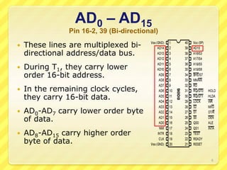
AD0 – AD15
Pin 16-2, 39 (Bi-directional)
 These lines are multiplexed bi-
directional address/data bus.
 During T1, they carry lower
order 16-bit address.
 In the remaining clock cycles,
they carry 16-bit data.
 AD0-AD7 carry lower order byte
of data.
 AD8-AD15 carry higher order
byte of data.
6
A19/S6, A18/S5, A17/S4, A16/S3
Pin 35-38 (Unidirectional)
 These lines are
multiplexed unidirectional
address and status bus.
 During T1, they carry
higher order 4-bit address.
 In the remaining clock
cycles, they carry status
signals.
7
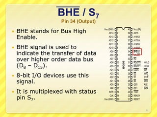
BHE / S7
Pin 34 (Output)
 BHE stands for Bus High
Enable.
 BHE signal is used to
indicate the transfer of data
over higher order data bus
(D8 – D15).
 8-bit I/O devices use this
signal.
 It is multiplexed with status
pin S7.
8
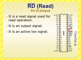
RD (Read)
Pin 32 (Output)
 It is a read signal used for
read operation.
 It is an output signal.
 It is an active low signal.
9
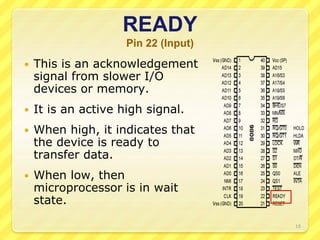
READY
Pin 22 (Input)
 This is an acknowledgement
signal from slower I/O
devices or memory.
 It is an active high signal.
 When high, it indicates that
the device is ready to
transfer data.
 When low, then
microprocessor is in wait
state.
10
RESET
Pin 21 (Input)
 It is a system reset.
 It is an active high signal.
 When high,
microprocessor enters into
reset state and terminates
the current activity.
 It must be active for at
least four clock cycles to
reset the microprocessor.
11
INTR
Pin 18 (Input)
 It is an interrupt request
signal.
 It is active high.
 It is level triggered.
12
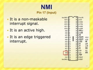
NMI
Pin 17 (Input)
 It is a non-maskable
interrupt signal.
 It is an active high.
 It is an edge triggered
interrupt.
13
TEST
Pin 23 (Input)
 It is used to test the
status of math co-
processor 8087.
 The BUSY pin of 8087 is
connected to this pin of
8086.
 If low, execution continues
else microprocessor is in
wait state.
14
CLK
Pin 19 (Input)
 This clock input provides
the basic timing for
processor operation.
 It is symmetric square
wave with 33% duty cycle.
 The range of frequency of
different versions is 5
MHz, 8 MHz and 10 MHz.
15
VCC and VSS
Pin 40 and Pin 20 (Input)
 VCC is power supply signal.
 +5V DC is supplied
through this pin.
 VSS is ground signal.
16
MN / MX
Pin 33 (Input)
 8086 works in two modes:
 Minimum Mode
 Maximum Mode
 If MN/MX is high, it works
in minimum mode.
 If MN/MX is low, it works
in maximum mode.
17
MN / MX
Pin 33 (Input)
 Pins 24 to 31 issue two
different sets of signals.
 One set of signals is issued
when CPU operates in
minimum mode.
 Other set of signals is
issued when CPU operates
in maximum mode.
18
Pin Description for
Minimum Mode
19
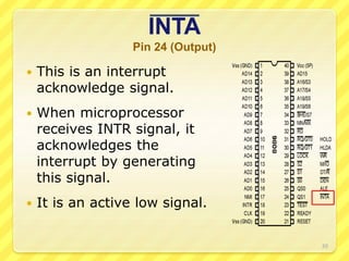
INTA
Pin 24 (Output)
 This is an interrupt
acknowledge signal.
 When microprocessor
receives INTR signal, it
acknowledges the
interrupt by generating
this signal.
 It is an active low signal.
20
ALE
Pin 25 (Output)
 This is an Address Latch
Enable signal.
 It indicates that valid
address is available on bus
AD0 – AD15.
 It is an active high signal
and remains high during T1
state.
 It is connected to enable pin
of latch 8282.
21
DEN
Pin 26 (Output)
 This is a Data Enable
signal.
 This signal is used to
enable the transceiver
8286.
 Transceiver is used to
separate the data from the
address/data bus.
 It is an active low signal.
22
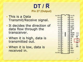
DT / R
Pin 27 (Output)
 This is a Data
Transmit/Receive signal.
 It decides the direction of
data flow through the
transceiver.
 When it is high, data is
transmitted out.
 When it is low, data is
received in.
23
M / IO
Pin 28 (Output)
 This signal is issued by the
microprocessor to
distinguish memory access
from I/O access.
 When it is high, memory is
accessed.
 When it is low, I/O devices
are accessed.
24
WR
Pin 29 (Output)
 It is a Write signal.
 It is used to write data in
memory or output device
depending on the status of
M/IO signal.
 It is an active low signal.
25
HLDA
Pin 30 (Output)
 It is a Hold Acknowledge
signal.
 It is issued after receiving
the HOLD signal.
 It is an active high signal.
26
HOLD
Pin 31 (Input)
 When DMA controller
needs to use address/data
bus, it sends a request to
the CPU through this pin.
 It is an active high signal.
 When microprocessor
receives HOLD signal, it
issues HLDA signal to the
DMA controller.
27
Pin Description for
Maximum Mode
28
QS1 and QS0
Pin 24 and 25 (Output)
 These pins provide the
status of instruction
queue.
29
QS1 QS0 Status
0 0 No operation
0 1 1st byte of opcode from queue
1 0 Empty queue
1 1 Subsequent byte from queue
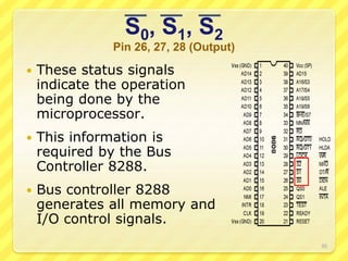
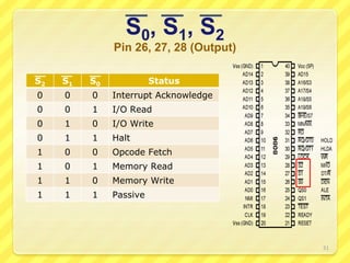
S0, S1, S2
Pin 26, 27, 28 (Output)
 These status signals
indicate the operation
being done by the
microprocessor.
 This information is
required by the Bus
Controller 8288.
 Bus controller 8288
generates all memory and
I/O control signals.
30
S0, S1, S2
Pin 26, 27, 28 (Output)
31
S2 S1 S0 Status
0 0 0 Interrupt Acknowledge
0 0 1 I/O Read
0 1 0 I/O Write
0 1 1 Halt
1 0 0 Opcode Fetch
1 0 1 Memory Read
1 1 0 Memory Write
1 1 1 Passive
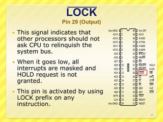
LOCK
Pin 29 (Output)
 This signal indicates that
other processors should not
ask CPU to relinquish the
system bus.
 When it goes low, all
interrupts are masked and
HOLD request is not
granted.
 This pin is activated by using
LOCK prefix on any
instruction.
32
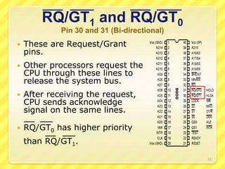
RQ/GT1 and RQ/GT0
Pin 30 and 31 (Bi-directional)
 These are Request/Grant
pins.
 Other processors request the
CPU through these lines to
release the system bus.
 After receiving the request,
CPU sends acknowledge
signal on the same lines.
 RQ/GT0 has higher priority
than RQ/GT1.
33
34