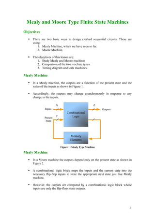
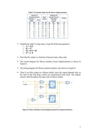
The document compares Mealy and Moore finite state machines. Mealy machines have outputs that are a function of both the present state and inputs, while Moore machines have outputs that are a function only of the present state. The document provides examples of Mealy and Moore machines that detect a "10" sequence and a "111" sequence. It discusses their state diagrams, circuit implementations, and timing diagrams. The timing diagram shows that Mealy machines can have invalid or "glitchy" outputs when the inputs change asynchronously, while Moore machines always have valid outputs.
A Mealy machine is a finite state machine that generates an output based on its current state and input. In contrast, a Moore machine's output depends only on its current state. The use of a Mealy machine often reduces the number of states needed compared to an equivalent Moore machine.
Finite-State Machine
The document discusses finite-state machines (FSM), which model sequential logic circuits. It describes two types of FSMs: Mealy and Moore machines. Mealy machines output depends on the present state and input, changing asynchronously with the clock. Moore machines' output depends only on the present state, changing synchronously with state changes and clock. The document provides an example of designing an FSM to output 0 if an even number of 1's have been received on the input, and 1 for odd. It shows solutions as both a Mealy and Moore machine using state transition tables and logic diagrams.
The document discusses the two types of finite state machines (FSMs): Mealy machines and Moore machines. Mealy machines have outputs that are a function of both the present state and present input, while Moore machines have outputs that are a function of just the present state. An example Moore machine is shown with a state diagram and state table that define its behavior. An example Mealy machine is also shown with a state diagram and state table.
Definition of finite state automaton: computation. It is an abstract machine that can be in exactly one of a finite number of states at any given time. The FSM can change from one state to another in response to some external inputs; the change from one state to another is called a transition. A FSM is defined by a list of its states, its initial state, and the conditions for each transition.
the report contain
Introduction
The historical of finite state automaton
Types of FSA
The advantages and disadvantages of FSA
examples for FSA
عمار عبد الكريم صاحب مبارك
AmmAr Abdualkareem sahib mobark
Flipflops and Excitation tables of flipflopsstudent
This document discusses latches and flip-flops. It explains that gates perform logic operations while flip-flops can store binary values. There are two types of sequential logic circuits: combinational using gates and sequential using flip-flops like the SR, D, JK, and T flip-flops. Flip-flops change state based on clock pulses in synchronous circuits or independent of clocks in asynchronous circuits.
The document explains about the concepts of sequential circuits in Digital electronics.
This will be helpful for the beginners in VLSI and electronics students.
This document discusses finite state machines (FSMs), specifically Moore and Mealy machines. It defines FSMs as circuits with a combinational block and memory block that can exist in multiple states, transitioning between states based on inputs. Moore machines output depends solely on the current state, while Mealy machines output depends on both the current state and inputs. Moore machines are safer since output only changes at clock edges, while Mealy machines are faster since output relies on inputs. Choosing between them depends on factors like whether synchronous/asynchronous operation is needed and whether speed or safety is a higher priority.
Mealy and Moore machines are types of finite state machines. A Mealy machine's output depends on its present state and input, while a Moore machine's output depends only on its present state. Mealy machines can be converted to Moore machines by breaking states with multiple outputs into multiple states, and vice versa by combining states with the same output. Both machine types have advantages and uses, with Mealy machines being faster but more expensive, and Moore machines being simpler but slower.
THIS PPT CONTAINS Definition,Principal components of a SM chart,ASM chart for combinational circuits,ASM chart in equivalent form,Example of development of ASM chart from Mealy Machine,Example of development of ASM chart from Moore Machine,Advantages of ASM chart
These slides have full understanding about Equivalent Moore Mealy... Having Moore to Mealy conversion and Mealy to Moore conversion...
These slides also describing the concept of Transducers as models of sequential circuits (both w.r.t Moore and Mealy)...
All these concepts are explained with easy examples...
The document discusses Mealy and Moore machine models. Mealy machines have an output function that depends on the present state and input, while Moore machines have an output function that depends only on the present state. The document provides examples of converting between Mealy and Moore machine representations.
This document provides an overview of registers and shift registers. It defines four types of shift registers based on data input/output: serial in parallel out (SIPO), parallel in serial out (PISO), serial in serial out (SISO), and parallel in parallel out (PIPO). Common integrated circuit shift registers like 74164 and 74195 are described. Applications of shift registers in arithmetic operations and counters like ring counters and Johnson counters are explained. Upon completing this chapter, students should understand registers, shift register types, their operations and applications.
- The document discusses the differences between Mealy and Moore models of sequential circuits.
- In a Mealy model, the output is a function of both the present state and input. In a Moore model, the output is a function of just the present state.
- Some key differences are that Mealy machines react faster to inputs but are more difficult to design, while Moore machines react more slowly but require less hardware and are easier to design.
Finite automaton discussed so far, is just associated with the RE or the language.
There is a question whether does there exist an FA which generates an output string corresponding to each input string ? The answer is yes. Such machines are called machines with output.
There are two types of machines with output.
Moore machine
Mealy machine
Equivalent machines Two machines are said to be equivalent if they print the same output string when the same input string is run on them.
This document provides an overview of finite state machines (FSMs). It defines an FSM as a digital circuit whose output depends on both the current input and state. There are two main types of FSMs: Moore machines whose output depends only on the current state, and Mealy machines whose output depends on both the current state and input. The document discusses state diagrams, state tables, basic circuit organization including latches to represent states and combinational logic for next states and outputs. It also covers topics like state assignment methods including one-hot encoding commonly used to map FSMs onto field programmable gate arrays due to their register-rich architecture.
The document discusses converting a pushdown automaton (PDA) to a context-free grammar (CFG) by constructing the CFG from the PDA's transition function. It also discusses deterministic PDAs and properties of languages accepted by deterministic PDAs, including that regular languages are accepted by deterministic PDAs and unambiguous CFGs correspond to languages of deterministic PDAs. The document also summarizes steps for eliminating useless symbols, epsilon productions, and unit productions from a CFG to put it in a normal form.
This document discusses latches and flip-flops. It describes the SR latch, gated SR latch, D latch, and gated D latch. It also covers edge-triggered flip-flops including the SR, D, and JK flip-flops. The key uses of flip-flops are for data storage, data transfer, counting, and frequency division in digital circuits and sequential logic.
This document provides an overview of sequential circuits such as latches and flip-flops. It defines sequential circuits and explains that they produce outputs based on current and previous inputs. The basic types of latches and flip-flops are described as SR, D, JK, and T. Characteristics of synchronous and asynchronous sequential circuits are also summarized. Common applications of sequential circuits include shift registers, counters, clocks, and storing temporary information in microprocessors. The document concludes by discussing specific sequential circuit components like SR latches, D flip-flops, and JK flip-flops in more detail.
Synchronous loadable up and down counter is a very important block in any complex digital system design. It is not just used for counting, it is also used for phase signal generation, clock division and for initiation of a process.
This document discusses finite state machines (FSMs), which are mathematical models used to model the behavior of systems that can be in one of a finite number of states. The document defines FSMs, describes their components and representations, compares deterministic and non-deterministic FSMs, and discusses their applications in areas like software engineering, hardware design, and modeling reactive systems. FSMs are a fundamental concept in automata theory and computational modeling.
1. Flip-flops and latches are types of memory elements used in sequential circuits. Latches change state based on input levels while flip-flops change state only on the rising or falling edge of a clock signal.
2. Common types of latches include the SR latch and D latch. Common types of flip-flops include the D flip-flop, JK flip-flop, and T flip-flop. Each has a characteristic truth table that defines its operation.
3. Sequential circuits can be analyzed using state tables that define the next state based on the present state and inputs. The state is defined by the values stored in all memory elements of the circuit.
Moore and Mealy machines are two types of finite state machines. A Mealy machine's output depends on the current state and input, and its output size equals its input size. A Moore machine's output depends only on the current state, and its output size is one larger than its input size. Mealy machines are defined as tuples including states, inputs, outputs, transitions, and an output function. Moore machines are similarly defined except the output function maps states to outputs rather than states and inputs. Examples of Moore and Mealy machine applications include elevators, compilers, SRAM, and vending machines.
The document discusses Moore automata, which is a type of finite state machine where the next state is determined by the current state alone, independently of the input. In a Moore automata, the output at a given time depends only on the current state of the machine. It consists of 6 tuples: a finite set of states Q, input alphabet set Σ, output alphabet set Δ, transition function δ mapping state-input pairs to the next state, and output function λ mapping each state to an output. The output in response to an input string is determined by the sequence of states entered and the corresponding outputs according to λ. A Moore machine always produces an output for the empty input string based on the initial state.
Programmable logic devices (PLDs) allow users to implement digital logic designs on a single chip. PLDs have advantages over traditional integrated circuits like lower costs for lower production volumes and shorter design times. Common types of PLDs include simple programmable logic devices like PALs, GALs, and CPLDs. PLDs are configured using memory like SRAM, EPROM, EEPROM, or flash to store the programmed logic pattern. Reprogrammability allows PLDs to be reused for different logic functions.
The document discusses sequential circuits and different types of flip flops and counters. It describes how sequential circuits have memory and their output depends on current and past inputs. There are two main types of sequential circuits - asynchronous which can change state at any time and synchronous which use a clock signal to control when the output can change state. Common types of flip flops described include SR, JK, D and T flip flops. Counters can be asynchronous with the clock signal rippling through or synchronous where all flip flops share the same clock.
The document discusses several types of programmable logic devices (PLDs) including PLAs, PALs, ROMs, CPLDs, and FPGAs. It provides details on how PLAs and PALs are structured, including their AND planes and OR planes. PALs are simpler than PLAs but less flexible. The document also describes how PALs can be used for multi-level logic design using macrocells and feedback to the AND plane. ROMs have a fixed AND plane and programmable OR plane to map logic functions. SPLDs refer to simpler PLDs like PLAs, PALs, and ROMs.
This document discusses finite state machines (FSMs) and compares Moore and Mealy machines. Moore machines output depends only on the current state, while Mealy machines output depends on both the current state and input. It provides examples of Mealy machine applications like traffic lights and vending machines. Mealy machines have advantages like reducing the number of states needed and generating faster output that changes immediately with input changes.
This document discusses the process of sequential circuit design using a sequence recognizer as an example. It begins with an overview of sequential circuits and sequence recognizers. It then walks through the full design process: 1) creating a state table and diagram, 2) assigning binary codes to states, 3) determining flip-flop input values, 4) deriving simplified equations, and 5) building the circuit. The example uses JK flip-flops but notes how it could also be built with D flip-flops.
This document describes the process for designing a synchronous state machine using both Mealy and Moore machine approaches. The steps include constructing a state diagram and table, assigning state variables, deriving excitation and output equations, and implementing the design using D or JK flip-flops. An example 3-state machine is designed to detect 3 or more consecutive 1's in an input signal. The example walks through obtaining the state diagram and table, assigning states, and deriving the logic equations for both Mealy and Moore machine implementations.
The document describes the analysis of clocked sequential circuits. It discusses:
- The behavior of clocked sequential circuits is determined by inputs, outputs, and flip-flop states.
- State equations specify the next state as a function of the present state and inputs.
- The analysis procedure involves obtaining input, output, and state equations and compiling a state table and state diagram.
- Clocked sequential circuits have memory elements like flip-flops, while their behavior over time is modeled through state equations and state diagrams.
The document provides information about an upcoming lab, homework assignments, and midterm for a class. It discusses Moore and Mealy finite state machines and gives examples to illustrate the differences between them. Details are also given about the topics and format for the upcoming Midterm 2 exam.
This document summarizes sequential circuits and finite state machines. It discusses:
- Representing state using state equations, state tables, and state diagrams
- Analyzing sequential circuits using D, JK, and T flip-flops
- The difference between Mealy and Moore machines and examples of each
- Design procedures for state machines including state diagrams, next state tables, excitation tables, K-maps, and circuit implementation
A state machine is a system that can be described by a set of states that the system transitions through. It has a set of inputs, outputs, and memory. There are two main types - Mealy machines where the output is a function of the state and inputs, and Moore machines where the output is only a function of the state. To design a state machine, you first understand the problem, draw a state diagram, reduce states if possible, assign states, and design the circuit from the state table. An example is a serial adder where each bit is added sequentially using states to track the carry.
1. The document outlines the 7 steps to analyze a synchronous state machine: determine excitation equations, transition equations, output equations, construct a transition table, add outputs to create a transition/output table, name states to create a state/output table, and draw a state diagram.
2. It then provides an example analysis: determine the excitation and transition equations, construct the transition table, determine the output equation, add outputs to the transition table to create a transition/output table, name states to create a state/output table, and draw the corresponding state diagram.
3. Key steps are determining the excitation, transition, and output equations, then using these to systematically construct the transition, state, and output tables
This document discusses a Moore finite state machine (FSM) with 8 distinct states plus a reset state. The Moore representation shows the current state, inputs that allow transition between states, and the corresponding outputs for each state. An example state transition diagram and truth table are provided for states 2 and 3 to illustrate the Moore representation. The next state table also shows the next state depending on the current state and input. Finally, the document asks the reader to represent the example FSM using a Mealy representation and implement it as a Mealy FSM.
The Quine-McCluskey method is used to minimize Boolean functions expressed in sum-of-products form. It works by generating prime implicants from the minterms and then eliminating variables to find an essential prime implicant. The method uses the Boolean rule A + A' = 1 repeatedly. It can handle incompletely specified functions using don't care conditions. The main steps are: 1) generate prime implicants, 2) construct a prime implicant table, 3) reduce the table by removing essential prime implicants and applying row and column dominance, 4) solve the reduced table.
1) The document discusses sequential logic circuits and covers topics like latches, flip-flops, their analysis and modeling in hardware description languages.
2) It describes various types of latches and flip-flops like SR, D, JK, T flip-flops and compares their operations.
3) Guidelines are provided for designing synchronous sequential circuits which include deriving a state diagram and table, reducing states, assigning codes, deriving equations and drawing the logic diagram.
This document discusses sequential circuits and their analysis and design. It begins by defining sequential circuits and their basic components like latches and flip-flops. It then covers analyzing synchronous sequential circuits using their output functions, state equations, and state tables. The document concludes by outlining the steps for designing a synchronous sequential circuit from its specification.
This document discusses various types of flip-flops including RS, D, JK, T flip-flops. It describes their characteristic tables and excitation tables. It also covers sequential circuits, state tables, state diagrams, state equations, and the design of counters using flip-flops. Key topics include the use of flip-flops as memory elements, master-slave configurations to prevent race-around conditions, and how to analyze and design sequential circuits and counters.
1. The document discusses sequential circuits and various types of latches and flip-flops used in sequential logic, including SR latches, D latches, edge-triggered flip-flops, JK flip-flops and T flip-flops.
2. It describes how to analyze sequential circuits using state tables, state equations, state diagrams and flip-flop input equations.
3. As an example, it shows the analysis of a 2-bit up counter sequential circuit using D flip-flops, including deriving the next state equations and constructing the state table and state diagram.
Digital circuits Electronics Digital circuits Electronics Digital circuits Electronics Digital circuits Electronics Digital circuits Electronics Digital circuits Electronics Digital circuits Electronics Digital circuits Electronics Digital circuits Electronics Digital circuits Electronics Digital circuits Electronics Digital circuits Electronics Digital circuits Electronics Digital circuits Electronics Digital circuits Electronics Digital circuits Electronics Digital circuits Electronics Digital circuits Electronics Digital circuits Electronics Digital circuits Electronics Digital circuits Electronics Digital circuits Electronics Digital circuits Electronics Digital circuits Electronics Digital circuits Electronics Digital circuits Electronics Digital circuits Electronics Digital circuits Electronics Digital circuits Electronics Digital circuits Electronics Digital circuits Electronics Digital circuits Electronics Digital circuits Electronics Digital circuits Electronics Digital circuits Electronics Digital circuits Electronics Digital circuits Electronics Digital circuits Electronics Digital circuits Electronics Digital circuits Electronics Digital circuits Electronics Digital circuits Electronics Digital circuits Electronics Digital circuits Electronics Digital circuits Electronics Digital circuits Electronics Digital circuits Electronics Digital circuits Electronics Digital circuits Electronics Digital circuits Electronics Digital circuits Electronics Digital circuits Electronics Digital circuits Electronics Digital circuits Electronics Digital circuits Electronics Digital circuits Electronics Digital circuits Electronics Digital circuits Electronics Digital circuits Electronics Digital circuits Electronics Digital circuits Electronics Digital circuits Electronics Digital circuits Electronics Digital circuits Electronics Digital circuits Electronics Digital circuits Electronics Digital circuits Electronics Digital circuits Electronics Digital circuits Electronics Digital circuits Electronics Digital circuits Electronics Digital circuits Electronics Digital circuits Electronics Digital circuits Electronics Digital circuits Electronics Digital circuits Electronics Digital circuits Electronics Digital circuits Electronics Digital circuits Electronics Digital circuits Electronics Digital circuits Electronics Digital circuits Electronics Digital circuits Electronics Digital circuits Electronics Digital circuits Electronics Digital circuits Electronics Digital circuits Electronics Digital circuits Electronics Digital circuits Electronics Digital circuits Electronics Digital circuits Electronics Digital circuits Electronics Digital circuits Electronics Digital circuits Electronics Digital circuits Electronics Digital circuits Electronics Digital circuits Electronics Digital circuits Electronics Digital circuits Electronics Digital circuits Electronics Digital circuits Electronics Digital circuits Electronics Digital circuits Electronics Digital circ
This document summarizes a lecture on finite state machine (FSM) design. It discusses Moore and Mealy machines, FSM word problems, state minimization, state assignment, and implementation. It provides examples of an odd parity checker, vending machine, and traffic light controller FSM designs. It also compares alternative representations like Algorithmic State Machines and describes analyzing and reverse engineering Moore and Mealy machines.
Designing Clocked Synchronous State MachineAbhilash Nair
The document describes the design of a synchronous state machine that detects a 0101 input sequence. It begins with the state diagram and transition table, then derives the excitation and output equations. The circuit diagram shows it uses D-type flip-flops for the state elements and logic gates to generate the next state and output based on the current state and input. It will output a 1 whenever the 0101 sequence is detected in the input stream and a 0 otherwise.
This document provides lecture materials on sequential logic implementation from CS 150 at Fall 2005. It covers:
1) Models for representing sequential circuits like finite state machines and their state diagrams.
2) The finite state machine design procedure including state assignment, derivation of state diagram and transition table.
3) Specifying outputs for Mealy and Moore machines using state diagrams.
4) Implementing finite state machines in Verilog including an example to reduce consecutive 1s in a string using both Mealy and Moore models.
5) Discussions around registered Mealy machines, synchronous behavior and differences between Mealy and Moore machines.
This document discusses various topics related to flip-flops and shift registers including:
1. Flip-flop timing parameters like setup time, hold time, and propagation delay.
2. The JK master-slave flip-flop configuration which uses two flip-flops to avoid unwanted state changes.
3. Switch contact bounce and how an RS latch can be used in a de-bounce circuit.
4. Different representations of flip-flops like truth tables, characteristic tables, and state diagrams.
5. HDL implementations of different types of flip-flops.
6. Shift register types like serial-in serial-out, serial-in parallel-out, parallel-in serial-
This document describes the process for designing sequential circuits. It involves specification, formulation, state assignment, determining flip-flop input and output equations, and verification. As an example, it walks through designing a circuit to recognize the input sequence 1101. It formulates a state diagram and state table, assigns binary codes to the states, derives the flip-flop input and output equations from the state table, and maps it to logic gates using available flip-flop technology.
The following presentation is a part of the level 4 module -- Digital Logic and Signal Principles. This resources is a part of the 2009/2010 Engineering (foundation degree, BEng and HN) courses from University of Wales Newport (course codes H101, H691, H620, HH37 and 001H). This resource is a part of the core modules for the full time 1st year undergraduate programme.
The BEng & Foundation Degrees and HNC/D in Engineering are designed to meet the needs of employers by placing the emphasis on the theoretical, practical and vocational aspects of engineering within the workplace and beyond. Engineering is becoming more high profile, and therefore more in demand as a skill set, in today’s high-tech world. This course has been designed to provide you with knowledge, skills and practical experience encountered in everyday engineering environments.
1. Mealy and Moore Type Finite State Machines
Objectives
There are two basic ways to design clocked sequential circuits. These are
using:
1. Mealy Machine, which we have seen so far.
2. Moore Machine.
The objectives of this lesson are:
1. Study Mealy and Moore machines
2. Comparison of the two machine types
3. Timing diagram and state machines
Mealy Machine
In a Mealy machine, the outputs are a function of the present state and the
value of the inputs as shown in Figure 1.
Accordingly, the outputs may change asynchronously in response to any
change in the inputs.
Figure 1: Mealy Type Machine
Mealy Machine
In a Moore machine the outputs depend only on the present state as shown in
Figure 2.
A combinational logic block maps the inputs and the current state into the
necessary flip-flop inputs to store the appropriate next state just like Mealy
machine.
However, the outputs are computed by a combinational logic block whose
inputs are only the flip-flops state outputs.
1
2. The outputs change synchronously with the state transition triggered by the
active clock edge.
Figure 2: Moore Type Machine
Comparison of the Two Machine Types
Consider a finite state machine that checks for a pattern of ‘10’ and asserts
logic high when it is detected.
The state diagram representations for the Mealy and Moore machines are
shown in Figure 3.
The state diagram of the Mealy machine lists the inputs with their associated
outputs on state transitions arcs.
The value stated on the arrows for Mealy machine is of the form Zi/Xi where
Zi represents input value and Xi represents output value.
A Moore machine produces a unique output for every state irrespective of
inputs.
Accordingly the state diagram of the Moore machine associates the output
with the state in the form state-notation/output-value.
The state transition arrows of Moore machine are labeled with the input value
that triggers such transition.
Since a Mealy machine associates outputs with transitions, an output sequence
can be generated in fewer states using Mealy machine as compared to Moore
machine. This was illustrated in the previous example.
2
3. Figure 3: Mealy and Moore State Diagrams for '10' Sequence Detector
Timing Diagrams
To analyze Mealy and Moore machine timings, consider the following
problem. A state-machine outputs ‘1’ if the input is ‘1’ for three consecutive
clocks.
Figure 4: Mealy State Machine for '111' Sequence Detector
3
4. Mealy State Machine
The Mealy machine state diagram is shown in Figure 4.
Note that there is no reset condition in the state machine that employs two flip-
flops. This means that the state machine can enter its unused state ‘11’ on start
up.
To make sure that machine gets resetted to a valid state, we use a ‘Reset’
signal.
The logic diagram for this state machine is shown in Figure 5. Note that
negative edge triggered flip-flops are used.
Figure 5: Mealy State Machine Circuit Implementation
Timing Diagram for the circuit is shown in Figure 6.
Since the output in Mealy model is a combination of present state and input
values, an unsynchronized input with triggering clock may result in invalid
output, as in the present case.
Consider the present case where input ‘x’ remains high for sometime after
state ‘AB = 10’ is reached. This results in ‘False Output’, also known as
‘Output Glitch’.
4
5. Figure 6: Timing Diagram for Mealy Model Sequence Detector
Moore State Machine
The Moore machine state diagram for ‘111’ sequence detector is shown in
Figure 7.
The state diagram is converted into its equivalent state table (See Table 1).
The states are next encoded with binary values and we achieve a state
transition table (See Table 2).
Figure 7: Moore Machine State Diagram
5
6. Table 1: State Table
Present Next State Output
State x=0 x=1 Z
Initial Initial Got-1 0
Got-1 Initial Got-11 0
Got-11 Initial Got-111 0
Got-111 Initial Got-111 1
Table 2: State Transition Table and Output Table
Present Next State Output
State x=0 x=1 Z
Initial Initial Got-1 0
Got-1 Initial Got-11 0
Got-11 Initial Got-111 0
Got-111 Initial Got-111 1
We will use JK and D flip-flops for the Moore circuit implementation. The
excitation tables for JK and D flip-flops (Table 3 & 4) are referenced to
tabulate excitation table (See Table 5).
Table 3: Excitation Table for JK flip-flop
Q(t) Q(t+1) J K
0 0 0 X
0 1 1 X
1 0 X 1
1 1 X 0
Table 4: Excitation Table for D flip-flop
Q(t) Q(t+1) D
0 0 0
0 1 1
1 0 0
1 1 1
6
7. Table 5: Excitation Table for the Moore Implementation
Inputs of Outputs of
Comb.Circuits Next Comb.Circuit
Output
Present State Flip-flop
Input
State Inputs
A B X A B JA KA DB Z
0 0 0 0 0 0 X 0 0
0 0 1 0 1 0 X 1 0
0 1 0 0 0 0 X 0 0
0 1 1 1 0 1 X 0 0
1 0 0 0 0 X 1 0 0
1 0 1 1 1 X 0 1 0
1 1 0 0 0 X 1 0 1
1 1 1 1 1 X 0 1 1
Simplifying Table 5 using maps, we get the following equations:
o JA = X.B
o KA = X’
o DB =X(A + B)
o Z=A.B
Note that the output is a function of present state values only.
The circuit diagram for Moore machine circuit implementation is shown in
Figure 8.
The timing diagram for Moore machine model is also shown in Figure 9.
There is no false output in a Moore model, since the output depends only on
the state of the flop flops, which are synchronized with clock. The outputs
remain valid throughout the logic state in Moore model.
Figure 8: Moore Machine Circuit Implementation for Sequence Detector.
7