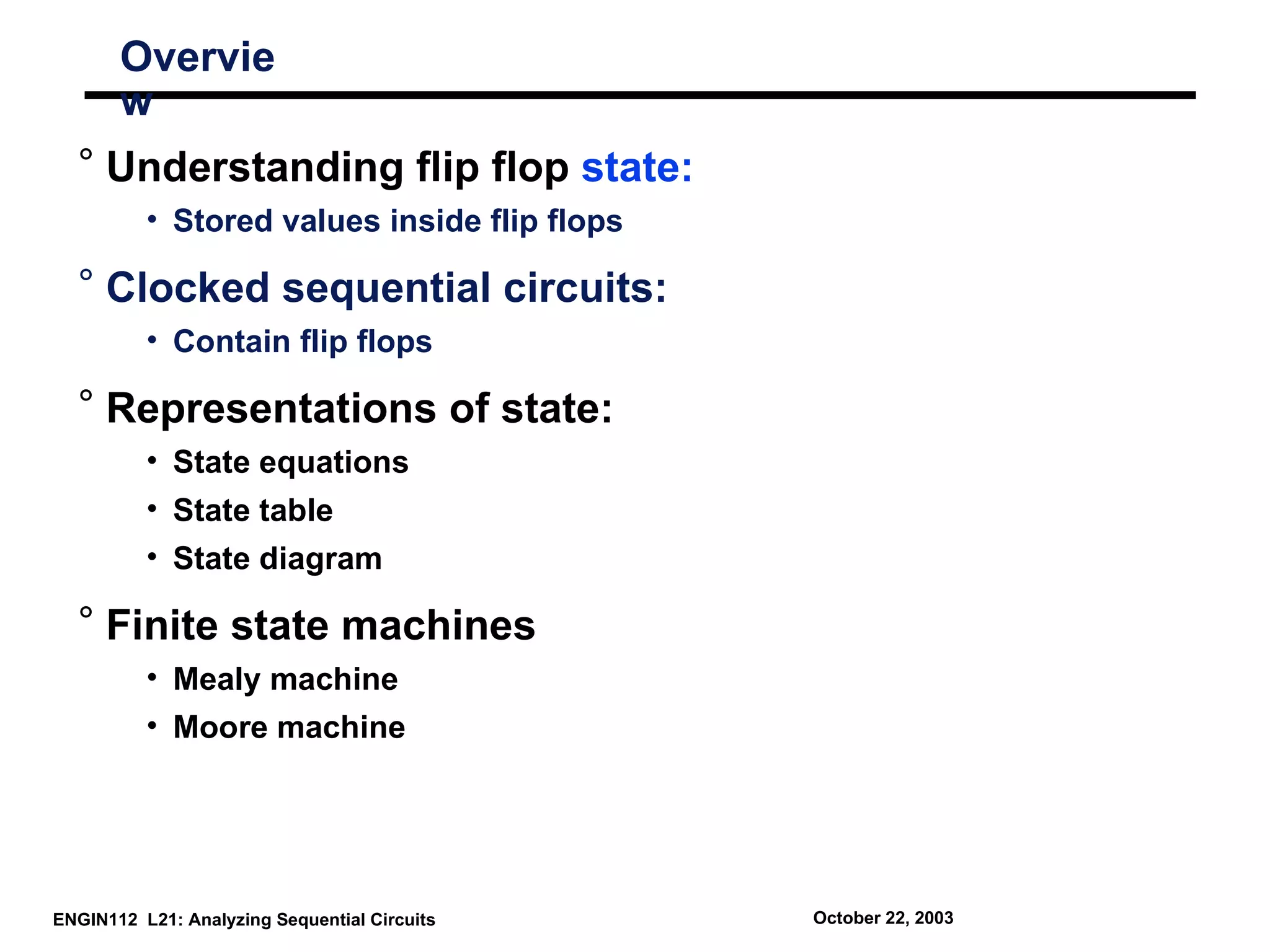
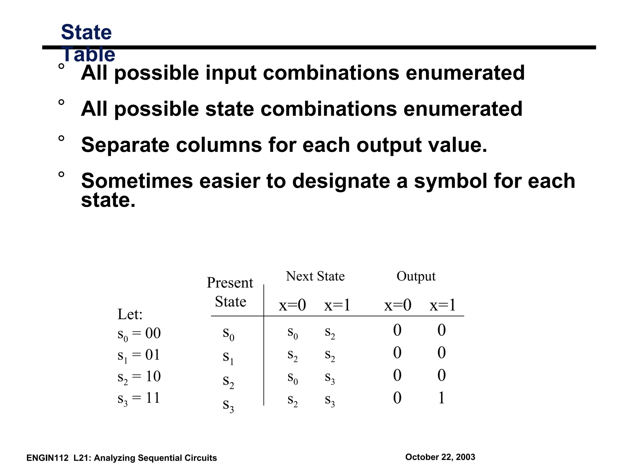
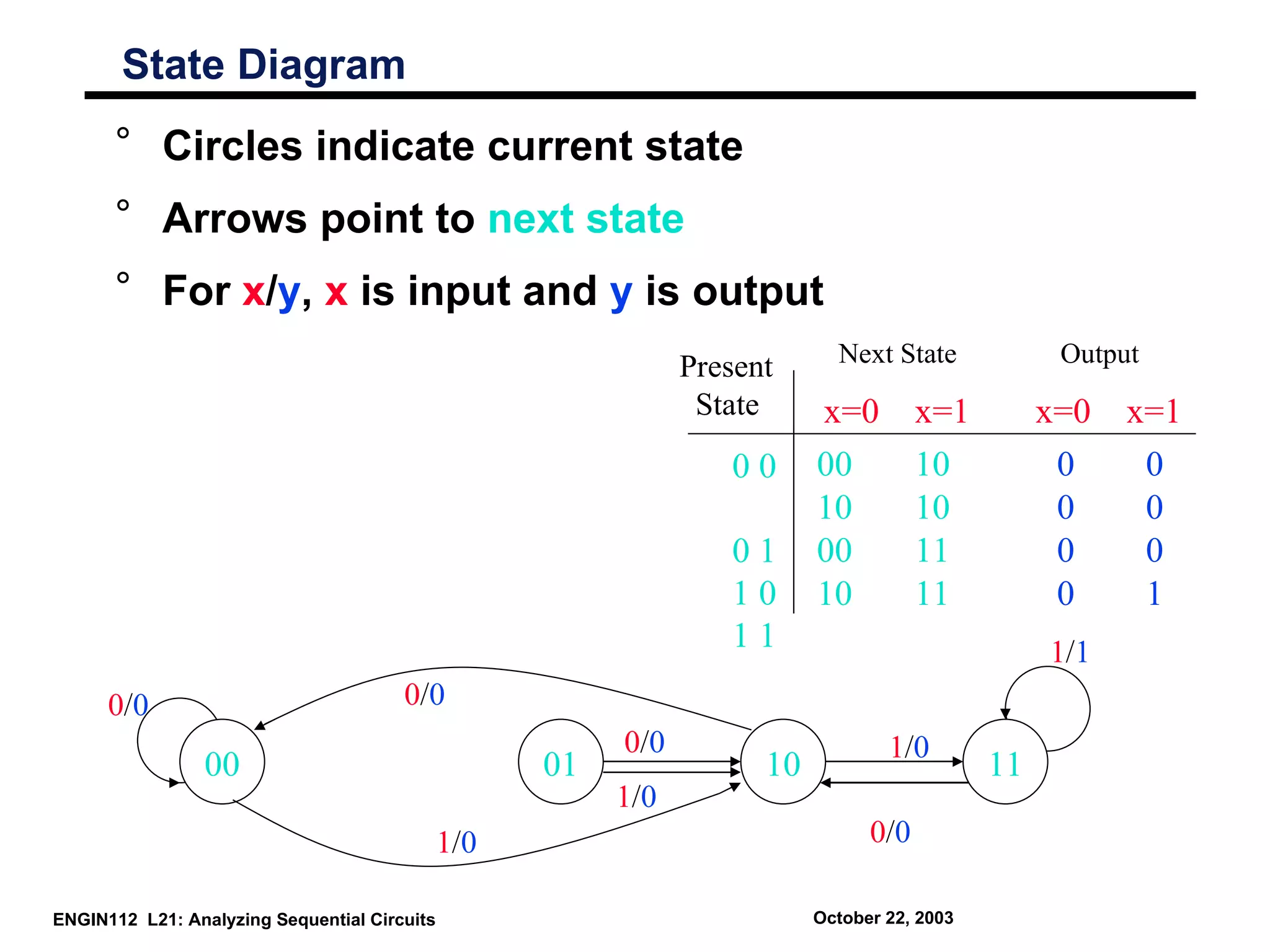
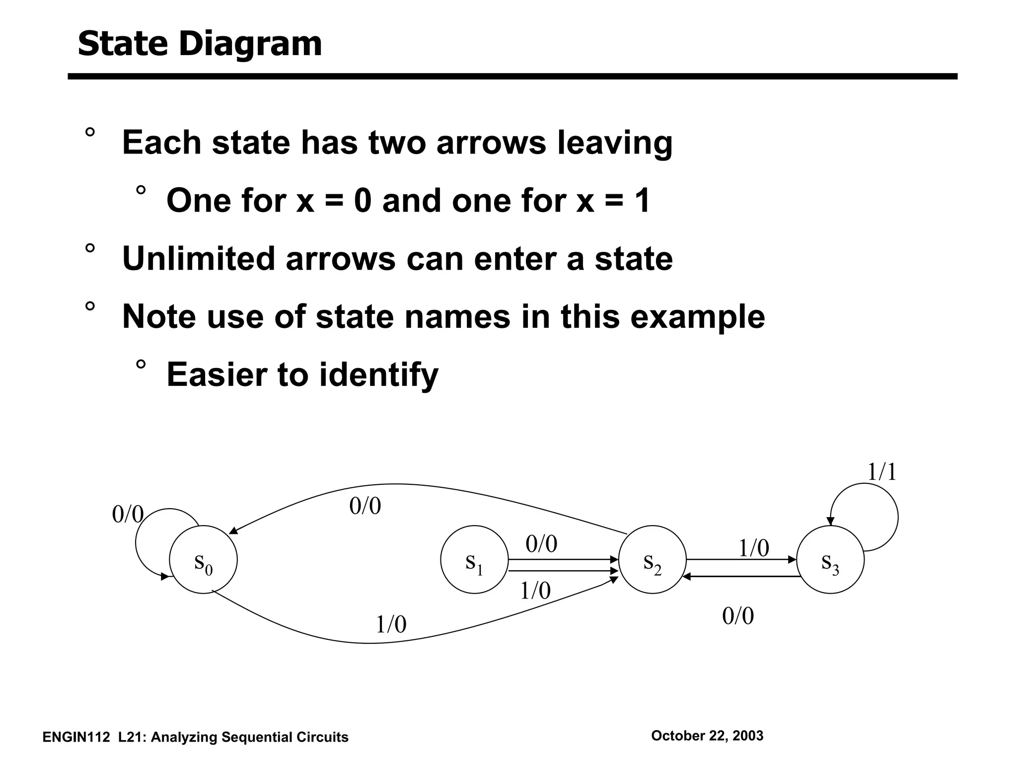
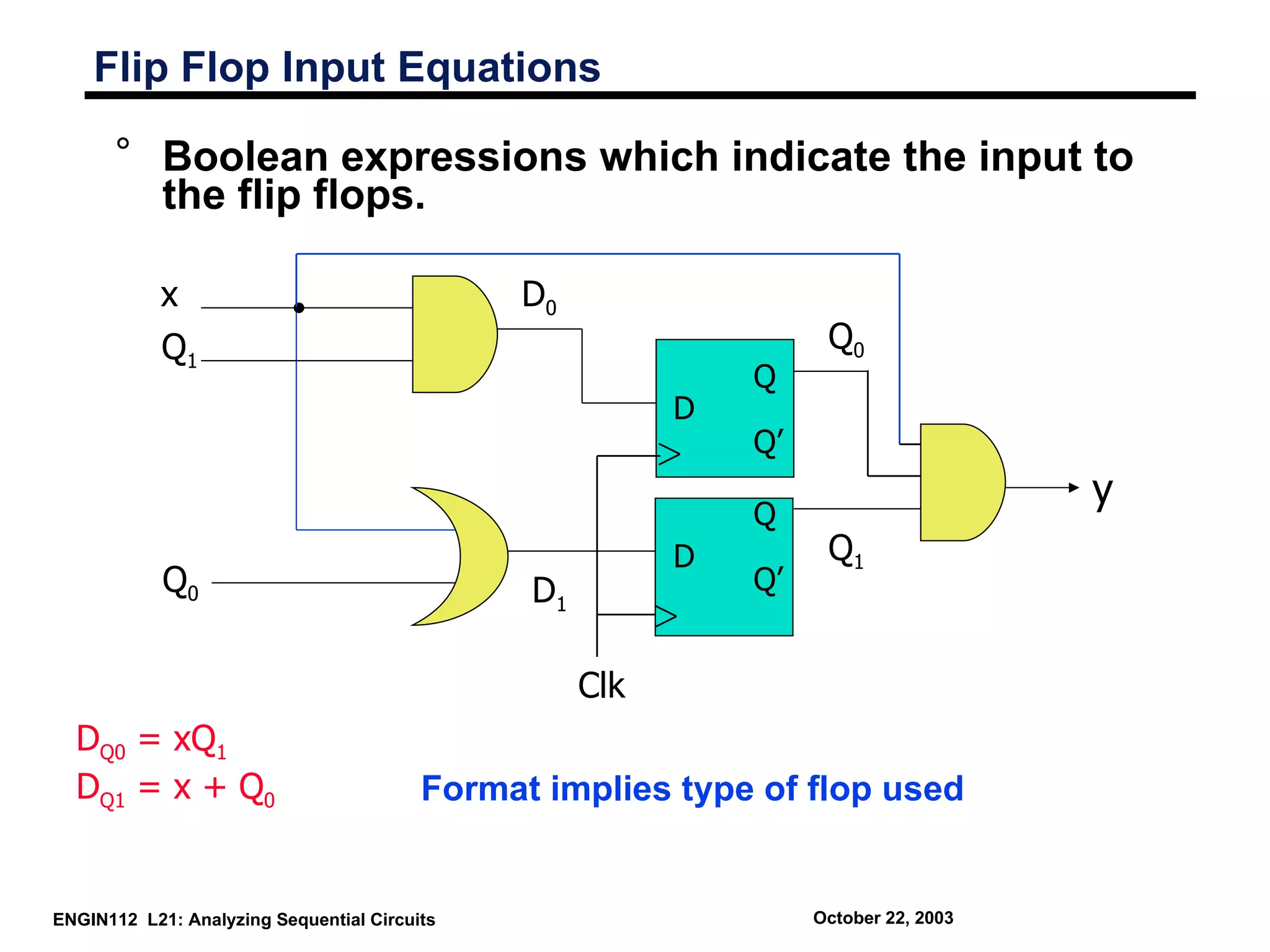
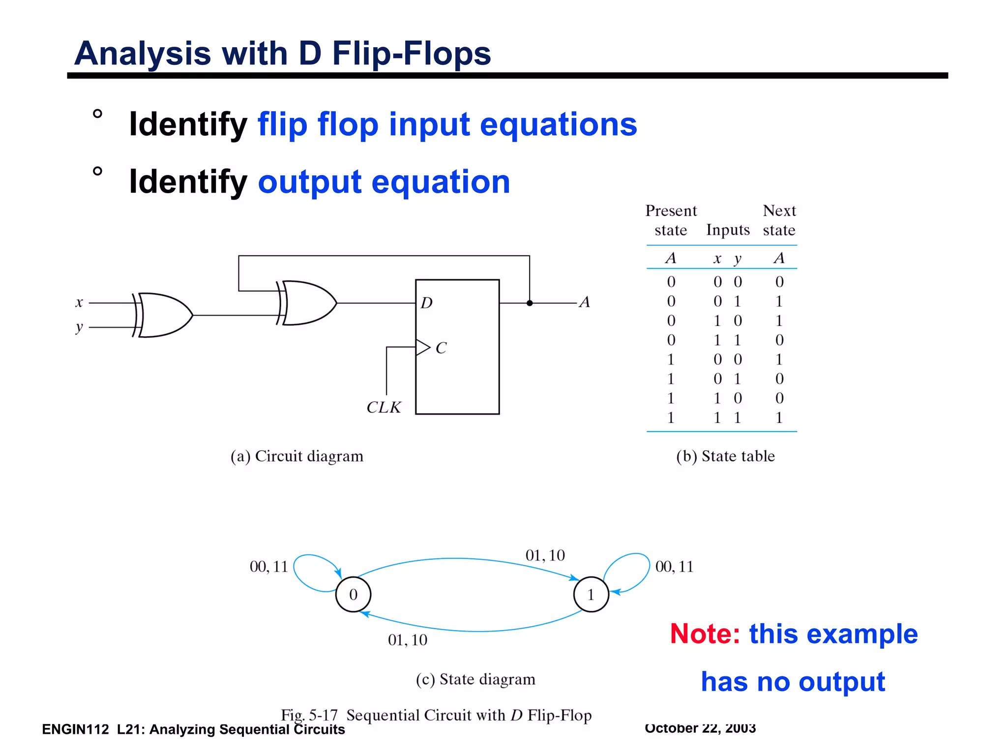
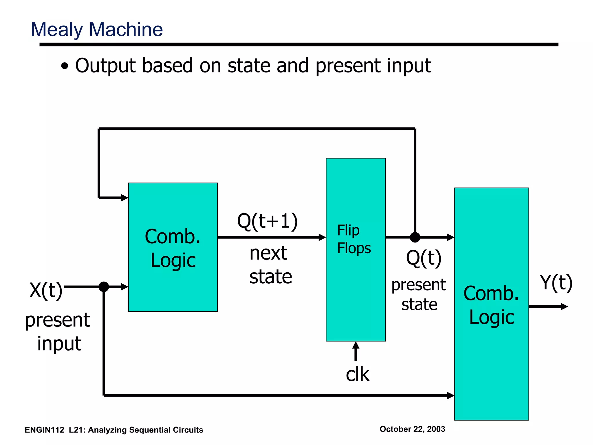
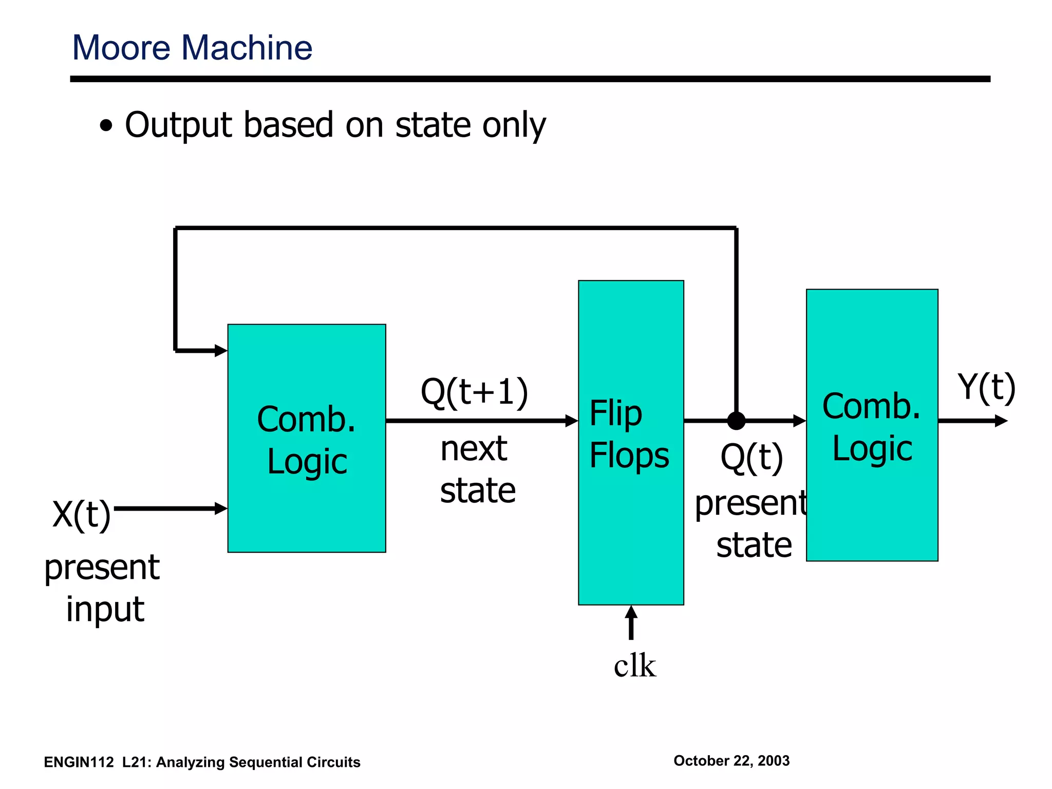
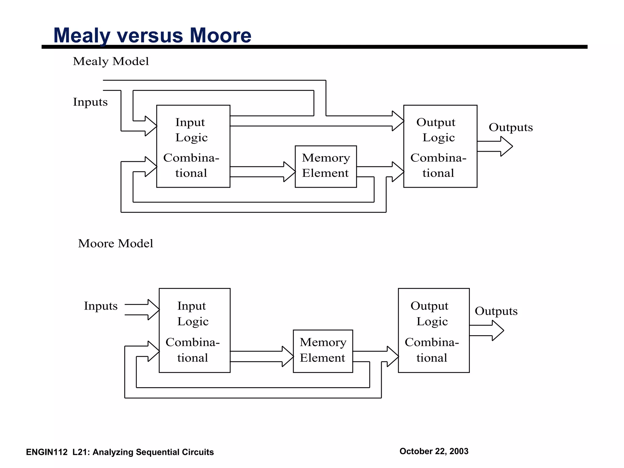
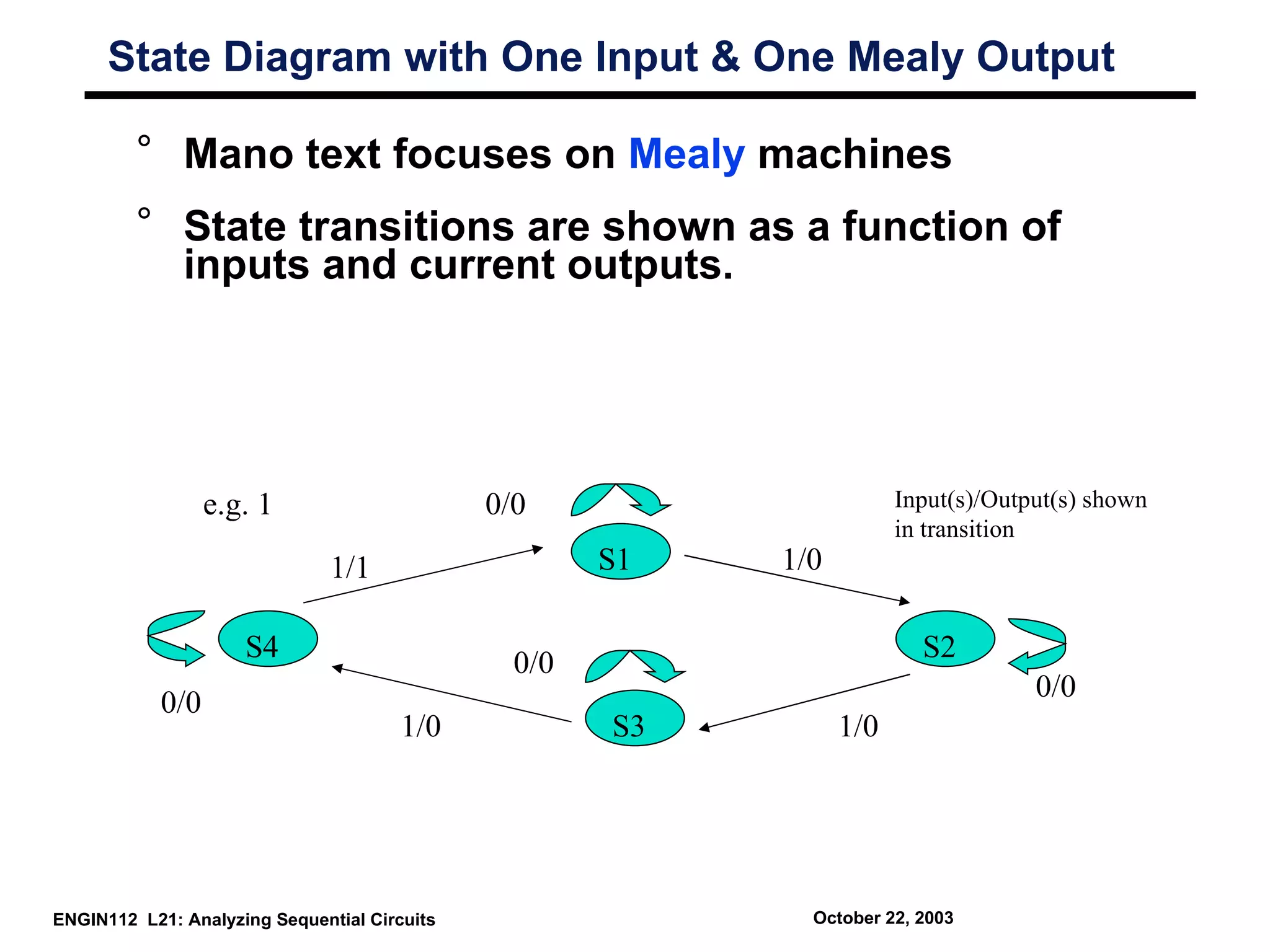
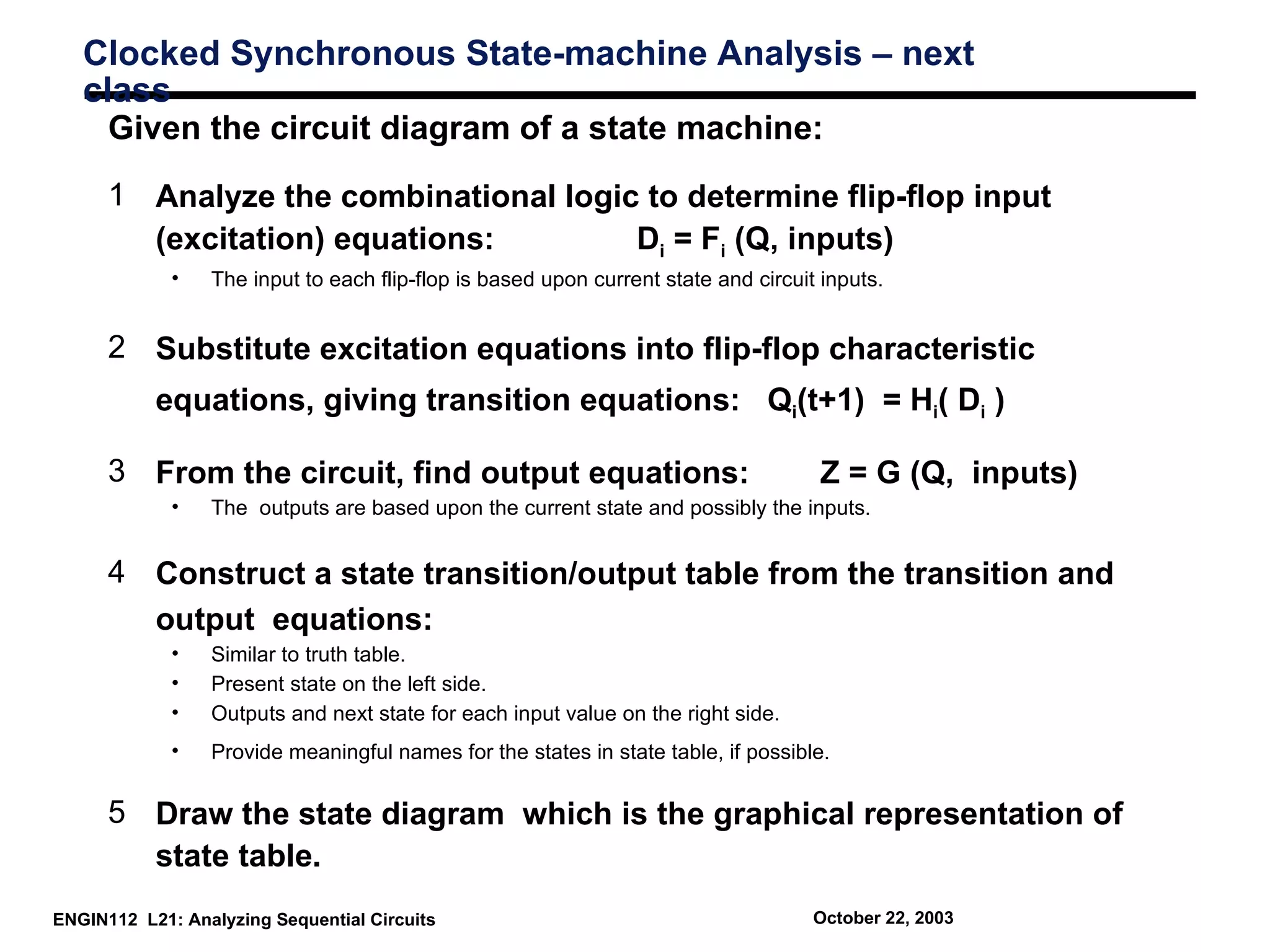
ENGIN 112
                 Intro to Electrical and Computer
                            Engineering
                                               Lecture 21
                          Analyzing Sequential Circuits


ENGIN112 L21: Analyzing Sequential Circuits                 October 22, 2003
Overvie
       w
  ° Understanding flip flop state:
          • Stored values inside flip flops

  ° Clocked sequential circuits:
          • Contain flip flops

  ° Representations of state:
          • State equations
          • State table
          • State diagram

  ° Finite state machines
          • Mealy machine
          • Moore machine


ENGIN112 L21: Analyzing Sequential Circuits   October 22, 2003
Flip Flop State

      ° Behavior of clocked sequential circuit can be
        determined from inputs, outputs and FF state
          x                                   D0
          Q1                                                      Q0
                                                             Q
                                                         D
                                                             Q’
                                                                                     y
                                                             Q
                                                         D        Q1
           Q0                                 D1             Q’


                                                   Clk

                                     y(t) = x(t)Q1(t)Q0(t)
                                     Q0(t+1) = D0(t) = x(t)Q1(t)
                                     Q1(t+1) = D1(t) = x(t) + Q0(t)

ENGIN112 L21: Analyzing Sequential Circuits                       October 22, 2003
Output and State Equations

       ° Next state dependent on previous state.

           x                                   D0
           Q1                                                      Q0
                                                              Q
                                                          D
                                                              Q’
                                                                                      y
                                                              Q
                                                          D        Q1
            Q0                                 D1             Q’


                                                    Clk
Output equation
                                      y(t) = x(t)Q1(t)Q0(t)
State equations                       Q0(t+1) = D0(t) = x(t)Q1(t)
                                      Q1(t+1) = D1(t) = x(t) + Q0(t)

 ENGIN112 L21: Analyzing Sequential Circuits                       October 22, 2003
State
      Table
      ° Sequence of outputs, inputs, and flip flop states
        enumerated in state table
      ° Present state indicates current value of flip flops
      ° Next state indicates state after next rising clock
        edge
      ° Output is output value on current clock edge

                                     Present        Next State    Output
                                      State       x=0     x=1    x=0    x=1
                                          00      00      10      0      0
      State Table                                 10      10      0      0
                                          01      00      11      0      0
                                          10      10      11      0      1
                                          11
                          Q1(t) Q0(t)         Q1(t+1) Q0(t+1)
ENGIN112 L21: Analyzing Sequential Circuits                            October 22, 2003
State
      Table
      ° All possible input combinations enumerated
      ° All possible state combinations enumerated
      ° Separate columns for each output value.
      ° Sometimes easier to designate a symbol for each
        state.


                                                   Next State    Output
                                        Present
                                         State     x=0   x=1    x=0    x=1
                    Let:
                    s0 = 00                   s0   s0    s2      0      0
                    s1 = 01                   s1   s2    s2      0      0
                    s2 = 10                   s2   s0    s3      0      0
                    s3 = 11                   s3   s2    s3      0      1


ENGIN112 L21: Analyzing Sequential Circuits                       October 22, 2003
State Diagram
      ° Circles indicate current state
      ° Arrows point to next state
      ° For x/y, x is input and y is output
                                                               Present      Next State             Output
                                                                State     x=0         x=1         x=0   x=1
                                                                  00      00          10           0     0
                                                                          10          10           0     0
                                                                  01      00          11           0     0
                                                                  10      10          11           0     1
                                                                  11                              1/1
      0/0                              0/0
                                                         0/0                      1/0
                 00                                 01               10                      11
                                                         1/0
                                              1/0                               0/0

ENGIN112 L21: Analyzing Sequential Circuits                               October 22, 2003
State Diagram

     ° Each state has two arrows leaving
            ° One for x = 0 and one for x = 1
     ° Unlimited arrows can enter a state
     ° Note use of state names in this example
            ° Easier to identify

                                                                                         1/1
         0/0                                  0/0
                                                           0/0               1/0
                     s0                               s1         s2                 s3
                                                           1/0
                                                1/0                        0/0


ENGIN112 L21: Analyzing Sequential Circuits                      October 22, 2003
Flip Flop Input Equations

      ° Boolean expressions which indicate the input to
        the flip flops.

            x                                 D0
            Q1                                                      Q0
                                                              Q
                                                          D
                                                              Q’
                                                                                      y
                                                              Q
                                                          D         Q1
            Q0                                 D1             Q’


                                                    Clk
  DQ0 = xQ1
  DQ1 = x + Q0                           Format implies type of flop used


ENGIN112 L21: Analyzing Sequential Circuits                        October 22, 2003
Analysis with D Flip-Flops

      ° Identify flip flop input equations
      ° Identify output equation


                                                 Note: this example
                                                     has no output
ENGIN112 L21: Analyzing Sequential Circuits   October 22, 2003
Mealy Machine
        • Output based on state and present input


                                              Q(t+1)   Flip
                            Comb.
                                               next    Flops
                            Logic                                    Q(t)
                                               state             present                  Y(t)
X(t)                                                                              Comb.
                                                                  state
present                                                                           Logic
 input
                                                        clk

ENGIN112 L21: Analyzing Sequential Circuits                    October 22, 2003
Moore Machine

       • Output based on state only


                                              Q(t+1)                                      Y(t)
                            Comb.                      Flip                       Comb.
                            Logic              next    Flops       Q(t)           Logic
                                               state             present
X(t)
                                                                  state
present
 input
                                                        clk

ENGIN112 L21: Analyzing Sequential Circuits                    October 22, 2003
Mealy versus Moore
          Mealy Model


          Inputs
                                  Input                    Output            Outputs
                                  Logic                     Logic
                               Combina-       Memory      Combina-
                                tional        Element      tional


           Moore Model


             Inputs               Input                   Output           Outputs
                                  Logic                    Logic
                               Combina-       Memory     Combina-
                                tional        Element     tional


ENGIN112 L21: Analyzing Sequential Circuits             October 22, 2003
State Diagram with One Input & One Mealy Output

         ° Mano text focuses on Mealy machines
         ° State transitions are shown as a function of
           inputs and current outputs.


                  e.g. 1                      0/0                      Input(s)/Output(s) shown
                                                                       in transition
                               1/1                    S1   1/0

                     S4                                                  S2
                                                0/0
                                                                                    0/0
            0/0
                                       1/0            S3         1/0


ENGIN112 L21: Analyzing Sequential Circuits                  October 22, 2003
State Diagram with One Input & a Moore
       Output
     ° Moore machine: outputs only depend on the
       current state
     ° Outputs cannot change during a clock pulse if the
       input variables change
     ° Moore Machines usually have more states.
     ° No direct path from inputs to outputs
     ° Can be more reliable


ENGIN112 L21: Analyzing Sequential Circuits   October 22, 2003
Clocked Synchronous State-machine Analysis – next
   class
     Given the circuit diagram of a state machine:
      1 Analyze the combinational logic to determine flip-flop input
        (excitation) equations:        Di = Fi (Q, inputs)
             •   The input to each flip-flop is based upon current state and circuit inputs.


      2 Substitute excitation equations into flip-flop characteristic
           equations, giving transition equations: Qi(t+1) = Hi( Di )

      3 From the circuit, find output equations:                                    Z = G (Q, inputs)
             •   The outputs are based upon the current state and possibly the inputs.


      4 Construct a state transition/output table from the transition and
        output equations:
             •   Similar to truth table.
             •   Present state on the left side.
             •   Outputs and next state for each input value on the right side.
             •   Provide meaningful names for the states in state table, if possible.


      5 Draw the state diagram which is the graphical representation of
        state table.
ENGIN112 L21: Analyzing Sequential Circuits                                         October 22, 2003
Summary


 ° Flip flops contain state information
 ° State can be represented in several forms:
        • State equations
        • State table
        • State diagram

 ° Possible to convert between these forms
 ° Circuits with state can take on a finite set of values
        • Finite state machine

 ° Two types of “machines”
        • Mealy machine
        • Moore machine


ENGIN112 L21: Analyzing Sequential Circuits   October 22, 2003

Lect21 Engin112

  • 1.
    ENGIN 112 Intro to Electrical and Computer Engineering Lecture 21 Analyzing Sequential Circuits ENGIN112 L21: Analyzing Sequential Circuits October 22, 2003
  • 2.
    Overvie w ° Understanding flip flop state: • Stored values inside flip flops ° Clocked sequential circuits: • Contain flip flops ° Representations of state: • State equations • State table • State diagram ° Finite state machines • Mealy machine • Moore machine ENGIN112 L21: Analyzing Sequential Circuits October 22, 2003
  • 3.
    Flip Flop State ° Behavior of clocked sequential circuit can be determined from inputs, outputs and FF state x D0 Q1 Q0 Q D Q’ y Q D Q1 Q0 D1 Q’ Clk y(t) = x(t)Q1(t)Q0(t) Q0(t+1) = D0(t) = x(t)Q1(t) Q1(t+1) = D1(t) = x(t) + Q0(t) ENGIN112 L21: Analyzing Sequential Circuits October 22, 2003
  • 4.
    Output and StateEquations ° Next state dependent on previous state. x D0 Q1 Q0 Q D Q’ y Q D Q1 Q0 D1 Q’ Clk Output equation y(t) = x(t)Q1(t)Q0(t) State equations Q0(t+1) = D0(t) = x(t)Q1(t) Q1(t+1) = D1(t) = x(t) + Q0(t) ENGIN112 L21: Analyzing Sequential Circuits October 22, 2003
  • 5.
    State Table ° Sequence of outputs, inputs, and flip flop states enumerated in state table ° Present state indicates current value of flip flops ° Next state indicates state after next rising clock edge ° Output is output value on current clock edge Present Next State Output State x=0 x=1 x=0 x=1 00 00 10 0 0 State Table 10 10 0 0 01 00 11 0 0 10 10 11 0 1 11 Q1(t) Q0(t) Q1(t+1) Q0(t+1) ENGIN112 L21: Analyzing Sequential Circuits October 22, 2003
  • 6.
    State Table ° All possible input combinations enumerated ° All possible state combinations enumerated ° Separate columns for each output value. ° Sometimes easier to designate a symbol for each state. Next State Output Present State x=0 x=1 x=0 x=1 Let: s0 = 00 s0 s0 s2 0 0 s1 = 01 s1 s2 s2 0 0 s2 = 10 s2 s0 s3 0 0 s3 = 11 s3 s2 s3 0 1 ENGIN112 L21: Analyzing Sequential Circuits October 22, 2003
  • 7.
    State Diagram ° Circles indicate current state ° Arrows point to next state ° For x/y, x is input and y is output Present Next State Output State x=0 x=1 x=0 x=1 00 00 10 0 0 10 10 0 0 01 00 11 0 0 10 10 11 0 1 11 1/1 0/0 0/0 0/0 1/0 00 01 10 11 1/0 1/0 0/0 ENGIN112 L21: Analyzing Sequential Circuits October 22, 2003
  • 8.
    State Diagram ° Each state has two arrows leaving ° One for x = 0 and one for x = 1 ° Unlimited arrows can enter a state ° Note use of state names in this example ° Easier to identify 1/1 0/0 0/0 0/0 1/0 s0 s1 s2 s3 1/0 1/0 0/0 ENGIN112 L21: Analyzing Sequential Circuits October 22, 2003
  • 9.
    Flip Flop InputEquations ° Boolean expressions which indicate the input to the flip flops. x D0 Q1 Q0 Q D Q’ y Q D Q1 Q0 D1 Q’ Clk DQ0 = xQ1 DQ1 = x + Q0 Format implies type of flop used ENGIN112 L21: Analyzing Sequential Circuits October 22, 2003
  • 10.
    Analysis with DFlip-Flops ° Identify flip flop input equations ° Identify output equation Note: this example has no output ENGIN112 L21: Analyzing Sequential Circuits October 22, 2003
  • 11.
    Mealy Machine • Output based on state and present input Q(t+1) Flip Comb. next Flops Logic Q(t) state present Y(t) X(t) Comb. state present Logic input clk ENGIN112 L21: Analyzing Sequential Circuits October 22, 2003
  • 12.
    Moore Machine • Output based on state only Q(t+1) Y(t) Comb. Flip Comb. Logic next Flops Q(t) Logic state present X(t) state present input clk ENGIN112 L21: Analyzing Sequential Circuits October 22, 2003
  • 13.
    Mealy versus Moore Mealy Model Inputs Input Output Outputs Logic Logic Combina- Memory Combina- tional Element tional Moore Model Inputs Input Output Outputs Logic Logic Combina- Memory Combina- tional Element tional ENGIN112 L21: Analyzing Sequential Circuits October 22, 2003
  • 14.
    State Diagram withOne Input & One Mealy Output ° Mano text focuses on Mealy machines ° State transitions are shown as a function of inputs and current outputs. e.g. 1 0/0 Input(s)/Output(s) shown in transition 1/1 S1 1/0 S4 S2 0/0 0/0 0/0 1/0 S3 1/0 ENGIN112 L21: Analyzing Sequential Circuits October 22, 2003
  • 15.
    State Diagram withOne Input & a Moore Output ° Moore machine: outputs only depend on the current state ° Outputs cannot change during a clock pulse if the input variables change ° Moore Machines usually have more states. ° No direct path from inputs to outputs ° Can be more reliable ENGIN112 L21: Analyzing Sequential Circuits October 22, 2003
  • 16.
    Clocked Synchronous State-machineAnalysis – next class Given the circuit diagram of a state machine: 1 Analyze the combinational logic to determine flip-flop input (excitation) equations: Di = Fi (Q, inputs) • The input to each flip-flop is based upon current state and circuit inputs. 2 Substitute excitation equations into flip-flop characteristic equations, giving transition equations: Qi(t+1) = Hi( Di ) 3 From the circuit, find output equations: Z = G (Q, inputs) • The outputs are based upon the current state and possibly the inputs. 4 Construct a state transition/output table from the transition and output equations: • Similar to truth table. • Present state on the left side. • Outputs and next state for each input value on the right side. • Provide meaningful names for the states in state table, if possible. 5 Draw the state diagram which is the graphical representation of state table. ENGIN112 L21: Analyzing Sequential Circuits October 22, 2003
  • 17.
    Summary ° Flipflops contain state information ° State can be represented in several forms: • State equations • State table • State diagram ° Possible to convert between these forms ° Circuits with state can take on a finite set of values • Finite state machine ° Two types of “machines” • Mealy machine • Moore machine ENGIN112 L21: Analyzing Sequential Circuits October 22, 2003

Editor's Notes

  • #2 Give qualifications of instructors: DAP teaching computer architecture at Berkeley since 1977 Co-athor of textbook used in class Best known for being one of pioneers of RISC currently author of article on future of microprocessors in SciAm Sept 1995 RY took 152 as student, TAed 152,instructor in 152 undergrad and grad work at Berkeley joined NextGen to design fact 80x86 microprocessors one of architects of UltraSPARC fastest SPARC mper shipping this Fall
  • #3 credential: bring a computer die photo wafer : This can be an hidden slide. I just want to use this to do my own planning. I have rearranged Culler’s lecture slides slightly and add more slides. This covers everything he covers in his first lecture (and more) but may We will save the fun part, “ Levels of Organization,” at the end (so student can stay awake): I will show the internal stricture of the SS10/20. Notes to Patterson: You may want to edit the slides in your section or add extra slides to taylor your needs.
  • #18 credential: bring a computer die photo wafer : This can be an hidden slide. I just want to use this to do my own planning. I have rearranged Culler’s lecture slides slightly and add more slides. This covers everything he covers in his first lecture (and more) but may We will save the fun part, “ Levels of Organization,” at the end (so student can stay awake): I will show the internal stricture of the SS10/20. Notes to Patterson: You may want to edit the slides in your section or add extra slides to taylor your needs.