This document discusses parity generators and checkers, which are used to detect errors in digital data transmission. It explains that a parity generator adds an extra parity bit to binary data to make the total number of 1s either even or odd. This allows a parity checker circuit at the receiver to detect errors if the number of 1s is the wrong parity. It provides truth tables and logic diagrams for 3-bit even and odd parity generators and an even parity checker. The boolean expressions for the parity generator and checker circuits are also derived.
What is ParityGenerator?
• A Parity Generator is a Combinational Logic Circuit that Generates the
Parity bit in the Transmitter.
• A Parity bit is used for the Purpose of Detecting Errors during
Transmissions of binary Information.
• It is an Extra bit Included with a binary Message to Make the Number
of 1’s either Odd or Even.
3.
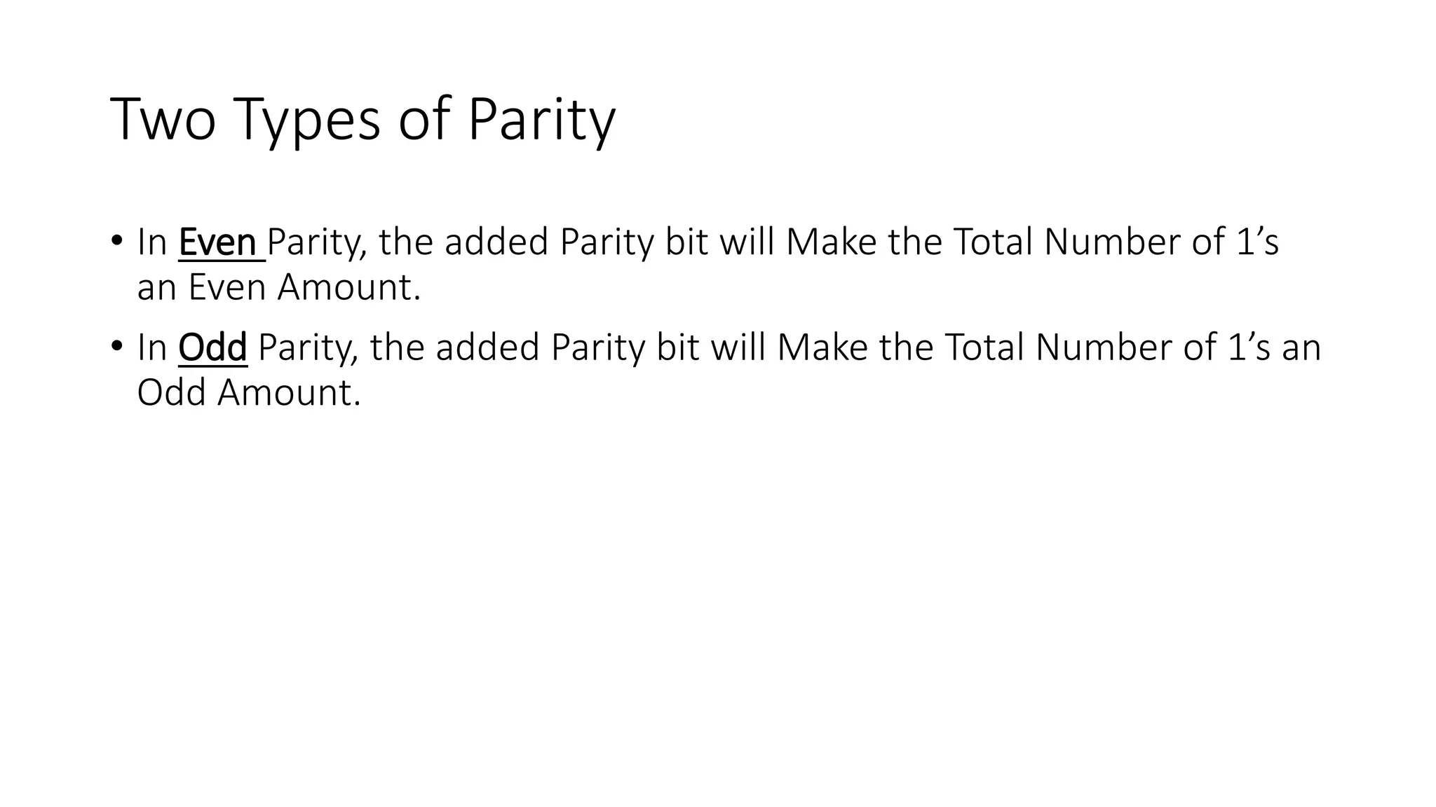
Two Types ofParity
• In Even Parity, the added Parity bit will Make the Total Number of 1’s
an Even Amount.
• In Odd Parity, the added Parity bit will Make the Total Number of 1’s an
Odd Amount.
4.
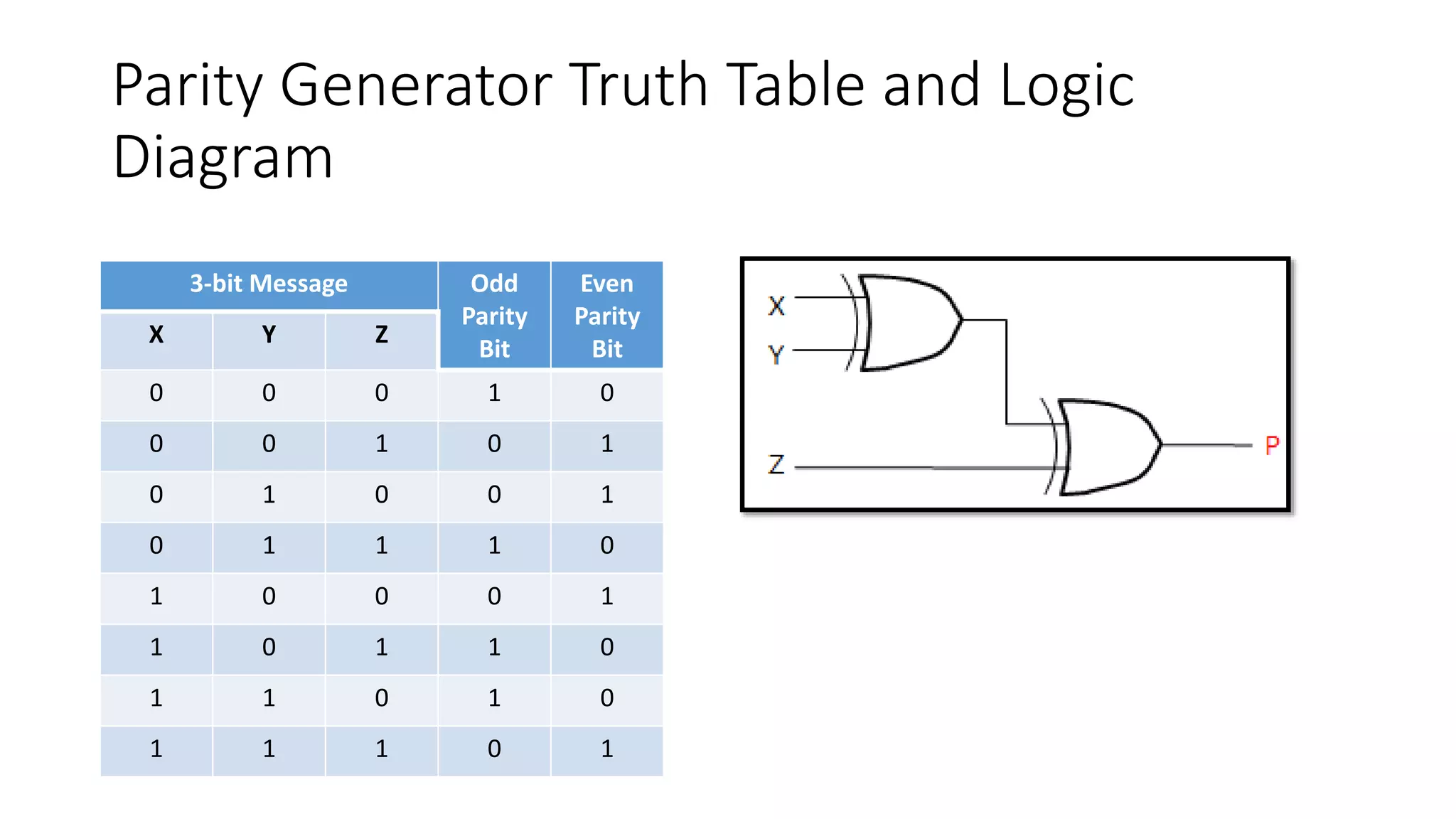
Parity Generator TruthTable and Logic
Diagram
3-bit Message Odd
Parity
Bit
Even
Parity
Bit
X Y Z
0 0 0 1 0
0 0 1 0 1
0 1 0 0 1
0 1 1 1 0
1 0 0 0 1
1 0 1 1 0
1 1 0 1 0
1 1 1 0 1
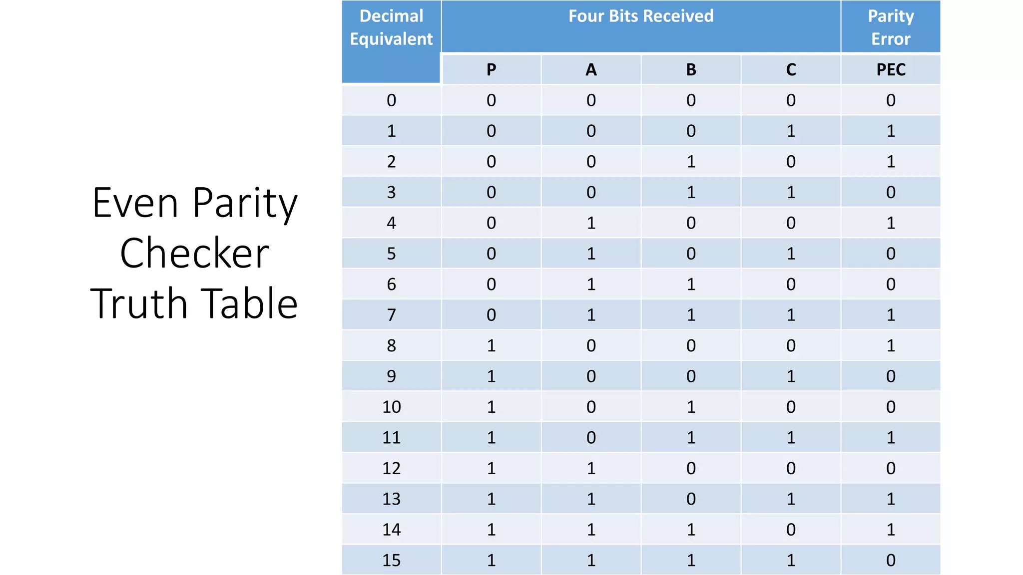
Parity Checker
• ACircuit that Checks the Parity in the Receiver is called Parity Checker.
• The Parity Checker Circuit Checks for Possible Errors in the
Transmission.
• Since the Information Transmitted with Even Parity, the Received must
have an even number of 1’s.If it has odd number of 1’s, it indicates
that there is a Error occurred during Transmission.
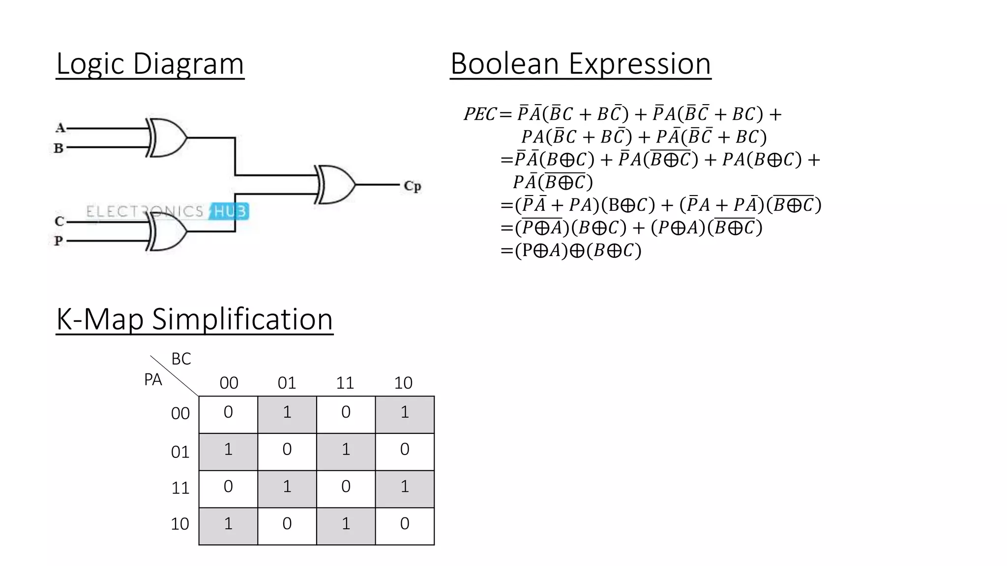
• The Output of the Parity Checker is denoted by PEC(Parity Error
Checker).If there is error, that is,if it has odd number of 1’s, it will
indicate 1.If no then PEC will indicate 0.