SlideShare a Scribd company logo
BY :-
ALAPAN RANJAN BANERJEE
The electronics signals are continuous and
can have any value over a given range,
are called analog signal.
The electrical signal which have only two
discreet value or level (high and low), is
called digital signal. Actual values of the
signal are unimportant.
 In this system, if 0 and 1 refer to the low and high
values respectively, the system is termed a
positive logic system.
 On the contrary, if 1 and 0 refer to the low and high
values respectively, the system is termed a
negative logic system.
 The signal between 0 and 1 volt can be recognized
as binary 0, between 3 and 5 volt can be taken as
binary 1. In digital system functions only in two
state, i.e. in a binary manner. The voltage is only
leveled low or high; its exact value is immaterial.
 A binary code represents text, computer
processor instructions, or any
other data using a two-symbol system. The
two-symbol system used is often the binary
number system's 0 and 1.
 The binary code assigns a pattern of binary
digits, also known as bits, to each character,
instruction, etc. For example, a
binary string of eight bits can represent any of
256 possible values and can therefore
represent a wide variety of different items.
BINARY CODE
NUMERIC CODE
BCD CODE XS-3 CODE GRAY CODE
ALPHANUMERIC
CODE
EBCDIC CODE ASCII CODE
 The Binary-coded Decimal uses the binary
number system to specify the decimal
numbers 0 to 9.
 It has four bits. The weights of the first
position is 20 (1), the second 21(2), the third
22(4), and the fourth 23(8). Reading from left to
right, the weights 8-4-2-1, hence it is called
8421 code.
 Valid BCD code are : 0000 to 1001
 Invalid BCD code are :1010 to 1111
As the name indicates, the excess-3
represents a decimal number, in binary
form, as a number greater than 3. An
excess-3 code is obtained by adding 3 to a
decimal number.
Valid excess-3 code : 0011 to 1100
Invalid excess-3 code :[0000 to 0010] and
[1101 to 1111]
 The Gray Code belongs to a class of code
called minimum-change code, in which only
one bit in the code group changes when
moving from one step to another step.
 The Gray Code is a non-weighted code.
Therefore it is not suitable arithmetic
operations but finds applications in
input/output devices and in some types of
analog to digital converters.
A code converters is a logic circuits whose
bit patterns representing numbers (or
characters) in one code and whose
outputs are the corresponding
representations in another code.
Code converters are usually multiple
output circuits.
 The K-map method of solving the
logical expressions is referred to
as the graphical technique of
simplifying Boolean expressions.
K-maps are also referred to as 2D
truth tables as each K-map is
nothing but a different format of
representing the values present in
a one-dimensional truth table.
 In K-maps, the rows and the
columns of the table use Gray
code-labeling which in turn
represent the values of the
corresponding input variables. This
means that each K-map cell can
be addressed using a unique Gray
Code-Word
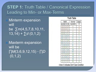
 Minterm expansion
will
be ∑m(4,5,7,8,10,11,
13,14) + ∑d (0,1,2)
 Maxterm expansion
will be
∏M(3,6,9,12,15) · ∏D
(0,1,2)
 we have to fill the K-
map cells with one for
each minterm, zero
for each maxterm,
and X for Don't Care
terms.
 The procedure is to
be repeated for every
single output variable.
 The process has to be initiated by grouping
the bits which lie in adjacent cells such that
the group formed contains the maximum
number of selected bits. This means that for
an n-variable K-map with 2ncells,
The procedure must be applied for all
adjacent cells of the K-map, even when they
appear to be not adjacent—the top row is
considered to be adjacent to the bottom row
and the rightmost column is considered to be
adjacent to the leftmost column
 A bit appearing in one group can be repeated
in another group provided that this leads to
the increase in the resulting group-size.
 Don’t Care conditions are to be considered
for the grouping activity if and only if they
help in obtaining a larger group.
Otherwise, they are to be neglected.
 For each of the resulting groups,
we have to obtain the
corresponding logical expression
in terms of the input-variables. This
can be done by expressing the bits
which are common amongst the
Gray code-words which represent
the cells contained within the
considered group.
 Thus, Y =
 B̅ D̅ + A̅ C̅ + A̅ BD + BC̅ D + AB̅ C
+ ACD̅
 OR Y = (A+B) (B+C+D̅ ) (A+C̅ +D)
(A̅ +B̅ +C+D) (A̅ +B̅ +C̅ +D̅ )
4-BIT BINARY 4-BIT GRAY
B4 B3 B2 B1 G4 G3 G2 G1
0 0 0 0
0 0 0 1
0 0 1 0
0 0 1 1
0 1 0 0
0 1 0 1
0 1 1 0
0 1 1 1
1 0 0 0
1 0 0 1
1 0 1 0
1 0 1 1
1 1 0 0
1 1 0 1
1 1 1 0
1 1 1 1
0 0 0 0
0 0 0 1
0 0 1 1
0 0 1 0
0 1 1 0
0 1 1 1
0 1 0 1
0 1 0 0
1 1 0 0
1 1 0 1
1 1 1 1
1 1 1 0
1 0 1 0
1 0 1 1
1 0 0 1
1 0 0 0
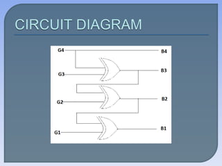
FOR G4 (G4=B4)
FOR G3 (G3=
B4.B3+B3.B4
B4⊕B3)
B2B1
B4B3
00 01 11 10
00 0 0 0 0
01 0 0 0 0
11 1 1 1 1
10 1 1 1 1
B2B1
B4B3
00 01 11 10
00 0 0 0 0
01 1 1 1 1
11 0 0 0 0
10 1 1 1 1
FOR G2 (G2=B2.B3+B3.B2
B2 ⊕B3)
FOR G1 (G1= B2.B3+B3.B2
B2 ⊕B1)
B2B1
B4B3
00 01 11 10
00 0 0 1 1
01 1 1 0 0
11 1 1 0 0
10 0 0 1 1
B2B1
B4B3
00 01 11 10
00 0 1 0 1
01 0 1 0 1
11 0 1 0 1
10 0 1 0 1
4 BIT GRAY 4 BIT BINARY
G4 G3 G2 G1 B4 B3 B2 B1
0 0 0 0
0 0 0 1
0 0 1 0
0 0 1 1
0 1 0 0
0 1 0 1
0 1 1 0
0 1 1 1
1 0 0 0
1 0 0 1
1 0 1 0
1 0 1 1
1 1 0 0
1 1 0 1
1 1 1 0
1 1 1 1
0 0 0 0
0 0 0 1
0 0 1 1
0 0 1 0
0 1 1 1
0 1 1 0
0 1 0 0
0 1 0 1
1 1 1 1
1 1 1 0
1 1 0 0
1 1 0 1
1 0 0 0
1 0 0 1
1 0 1 1
1 0 1 0
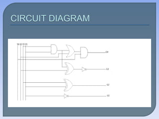
FOR B4 =G4
FOR B3= G4.G3+G3.G4
=G4⊕G3
G2G1
G4G3
00 01 11 10
00 0 0 0 0
01 0 0 0 0
11 1 1 1 1
10 1 1 1 1
G2G1
G4G3
00 01 11 10
00 0 0 0 0
01 1 1 1 1
11 0 0 0 0
10 1 1 1 1
FOR B2= G2⊕G3⊕G4 FOR B1=G1⊕G2⊕G3⊕G4
G2G1
G4G3
00 01 11 10
00 0 0 1 1
01 1 1 0 0
11 0 0 1 1
10 1 1 1 1
G2G1
G4G3
00 01 11 10
00 0 1 0 1
01 1 0 1 0
11 0 1 0 1
10 1 0 1 0
4-BIT BINARY 4-BIT BCD
B4 B3 B2 B1 Y4 Y3 Y2 Y1
0 0 0 0
0 0 0 1
0 0 1 0
0 0 1 1
0 1 0 0
0 1 0 1
0 1 1 0
0 1 1 1
1 0 0 0
1 0 0 1
1 0 1 0
1 0 1 1
1 1 0 0
1 1 0 1
1 1 1 0
1 1 1 1
0 0 0 0
0 0 0 1
0 0 1 0
0 0 1 1
0 1 0 0
0 1 0 1
0 1 1 0
0 1 1 1
1 0 0 0
1 0 0 1
X X X X
X X X X
X X X X
X X X X
X X X X
X X X X
FOR Y4=B4 FOR Y3=B3
B2B1
B4B3
00 01 11 10
00 0 0 0 0
01 0 0 0 0
11 X X X X
10 1 1 X X
B2B1
B4B3
00 01 11 10
00 0 0 1 1
01 1 1 1 1
11 X X X X
10 0 0 X X
FOR Y2=B2 FOR Y1=B1
B2B1
B4B3
00 01 11 10
00 0 0 1 1
01 0 0 1 1
11 X X X X
10 0 0 X X
B2B1
B4B3
00 01 11 10
00 0 1 1 0
01 0 1 1 0
11 X X X X
10 0 1 X X
4-BIT BCD 4-BIT EXCESS-3
B4 B3 B2 B1 Y4 Y3 Y2 Y1
0 0 0 0
0 0 0 1
0 0 1 0
0 0 1 1
0 1 0 0
0 1 0 1
0 1 1 0
0 1 1 1
1 0 0 0
1 0 0 1
0 0 1 1
0 1 0 0
0 1 0 1
0 1 1 0
0 1 1 1
1 0 0 0
1 0 0 1
1 0 1 0
1 0 1 1
1 1 0 0
FOR Y4= B4+B3.B1+B3.B2
FOR
Y3=B3.B1+B3.B2+B3.B2.B1
B2B1
B4B3
00 01 11 10
00 0 0 0 0
01 0 1 1 1
11 X X X X
10 1 1 X X
B2B1
B4B3
00 01 11 10
00 0 1 1 1
01 1 0 0 0
11 X X X X
10 0 1 X X
FOR Y2= B2.B1+B2.B1
FOR Y1=B2.B1+B2.B1
=B1
B2B1
B4B3
00 01 11 10
00 1 0 1 0
01 1 0 1 0
11 X X X X
10 1 0 X X
B2B1
B4B3
00 01 11 10
00 1 0 0 1
01 0 0 0 1
11 X X X X
10 1 0 X X
4-BIT EXCESS-3 4-BIT BCD
Y4 Y3 Y2 Y1 B4 B3 B2 B1
0 0 1 1
0 1 0 0
0 1 0 1
0 1 1 0
0 1 1 1
1 0 0 0
1 0 0 1
1 0 1 0
1 0 1 1
1 1 0 0
0 0 0 0
0 0 0 1
0 0 1 0
0 0 1 1
0 1 0 0
0 1 0 1
0 1 1 0
0 1 1 1
1 0 0 0
1 0 0 1
FOR B4=Y4(Y3+Y2.Y1)
FOR
B3=Y3.Y1+Y3.Y2+Y3.Y2.Y1
=Y3 ⊕Y2.Y1
Y2Y1
Y4Y3
00 01 11 10
00 X X 0 X
01 0 0 0 0
11 1 X X X
10 0 0 1 0
Y2Y1
Y4Y3
00 01 11 10
00 X X 0 X
01 0 0 1 0
11 0 X X X
10 1 1 0 1
FOR B2=Y2 ⊕Y1
FOR B1=Y2.Y1+Y2.Y1
=Y1
Y2Y1
Y4Y3
00 01 11 10
00 X X 0 X
01 0 1 0 1
11 X X X X
10 0 1 0 1
Y2Y1
Y4Y3
00 01 11 10
00 X X 0 X
01 1 0 0 1
11 1 X X X
10 1 0 X 1
 WEIGHTED AND NON-WEIGHTED CODE
 SEQUEMTIAL CODE
 SELF COMPLEMENTING CODE
 CYCLIC CODE
 REFLECTIVE CODE
ASCII CODE
EBCDIC CODE
 The ASCII code- American Standards Code For Information
Interchange is used in most microcomputers by its
manufacturers.
 This code is represented by 7 bit binary combination
 EBDIC or Extended Binary Coded Decimal Interchange Code is
used in IB equipment.
 It differs from ASCII code only in its grouping for the different
alphanumeric characters.
 It uses 8 bits for each characters.
Code conversion

More Related Content

What's hot

Multiplication algorithm
Multiplication algorithmMultiplication algorithm
Multiplication algorithm
Gaurav Subham
 
Code conversions.pptx415.pptx
Code conversions.pptx415.pptxCode conversions.pptx415.pptx
Code conversions.pptx415.pptx
MariaJoseph591921
 
Encoder & Decoder
Encoder & DecoderEncoder & Decoder
Encoder & Decoder
Syed Saeed
 
Combinational circuits
Combinational circuitsCombinational circuits
Combinational circuits
SARITHA REDDY
 
Binary multipliers
Binary multipliersBinary multipliers
Binary multipliers
Syed Saeed
 
Synchronous Counter
Synchronous Counter Synchronous Counter
Synchronous Counter
Akhilesh Kushwaha
 
Universal Gates - Aneesa N Ali
Universal Gates - Aneesa N AliUniversal Gates - Aneesa N Ali
Universal Gates - Aneesa N Ali
Dipayan Sarkar
 
Sequential circuits
Sequential circuitsSequential circuits
Sequential circuits
Jaipal Dhobale
 
Digital Logic & Design
Digital Logic & DesignDigital Logic & Design
Digital Logic & Design
Rokonuzzaman Rony
 
13 Boolean Algebra
13 Boolean Algebra13 Boolean Algebra
13 Boolean Algebra
Praveen M Jigajinni
 
Adder & subtractor (Half adder, Full adder, Half subtractor, Full subtractor)
Adder & subtractor (Half adder, Full adder, Half subtractor, Full subtractor)Adder & subtractor (Half adder, Full adder, Half subtractor, Full subtractor)
Adder & subtractor (Half adder, Full adder, Half subtractor, Full subtractor)
ISMT College
 
SHIFT REGISTERS
SHIFT REGISTERSSHIFT REGISTERS
SHIFT REGISTERS
kumari36
 
Binary codes
Binary codesBinary codes
Binary codes
GargiKhanna1
 
Counters
CountersCounters
Counters
Ketaki_Pattani
 
Adder substracter
Adder substracterAdder substracter
Adder substracter
WanNurdiana
 
Bcd to excess 3 code converter
Bcd to excess 3 code converterBcd to excess 3 code converter
Bcd to excess 3 code converter
Ushaswini Chowdary
 
Digital Logic Circuits
Digital Logic CircuitsDigital Logic Circuits
Digital Logic Circuits
sathish sak
 
Chapter 4. logic function and boolean algebra
Chapter 4. logic function and boolean algebraChapter 4. logic function and boolean algebra
Chapter 4. logic function and boolean algebra
Ashish KC
 
Weighted and Non Weighted Codes
Weighted and Non Weighted CodesWeighted and Non Weighted Codes
Weighted and Non Weighted Codes
SubhamSatpathy2
 
Binary codes
Binary codesBinary codes
Binary codes
ZareenRauf1
 

What's hot (20)

Multiplication algorithm
Multiplication algorithmMultiplication algorithm
Multiplication algorithm
 
Code conversions.pptx415.pptx
Code conversions.pptx415.pptxCode conversions.pptx415.pptx
Code conversions.pptx415.pptx
 
Encoder & Decoder
Encoder & DecoderEncoder & Decoder
Encoder & Decoder
 
Combinational circuits
Combinational circuitsCombinational circuits
Combinational circuits
 
Binary multipliers
Binary multipliersBinary multipliers
Binary multipliers
 
Synchronous Counter
Synchronous Counter Synchronous Counter
Synchronous Counter
 
Universal Gates - Aneesa N Ali
Universal Gates - Aneesa N AliUniversal Gates - Aneesa N Ali
Universal Gates - Aneesa N Ali
 
Sequential circuits
Sequential circuitsSequential circuits
Sequential circuits
 
Digital Logic & Design
Digital Logic & DesignDigital Logic & Design
Digital Logic & Design
 
13 Boolean Algebra
13 Boolean Algebra13 Boolean Algebra
13 Boolean Algebra
 
Adder & subtractor (Half adder, Full adder, Half subtractor, Full subtractor)
Adder & subtractor (Half adder, Full adder, Half subtractor, Full subtractor)Adder & subtractor (Half adder, Full adder, Half subtractor, Full subtractor)
Adder & subtractor (Half adder, Full adder, Half subtractor, Full subtractor)
 
SHIFT REGISTERS
SHIFT REGISTERSSHIFT REGISTERS
SHIFT REGISTERS
 
Binary codes
Binary codesBinary codes
Binary codes
 
Counters
CountersCounters
Counters
 
Adder substracter
Adder substracterAdder substracter
Adder substracter
 
Bcd to excess 3 code converter
Bcd to excess 3 code converterBcd to excess 3 code converter
Bcd to excess 3 code converter
 
Digital Logic Circuits
Digital Logic CircuitsDigital Logic Circuits
Digital Logic Circuits
 
Chapter 4. logic function and boolean algebra
Chapter 4. logic function and boolean algebraChapter 4. logic function and boolean algebra
Chapter 4. logic function and boolean algebra
 
Weighted and Non Weighted Codes
Weighted and Non Weighted CodesWeighted and Non Weighted Codes
Weighted and Non Weighted Codes
 
Binary codes
Binary codesBinary codes
Binary codes
 

Similar to Code conversion

Combinational Logic Circuit
Combinational Logic CircuitCombinational Logic Circuit
Combinational Logic Circuit
GargiKhanna1
 
Unit_2_Boolean_algebra_and_Karnaugh_maps.pptx
Unit_2_Boolean_algebra_and_Karnaugh_maps.pptxUnit_2_Boolean_algebra_and_Karnaugh_maps.pptx
Unit_2_Boolean_algebra_and_Karnaugh_maps.pptx
Kartikkalaspurkar1
 
Unit 4 combinational circuit
Unit 4 combinational circuitUnit 4 combinational circuit
Unit 4 combinational circuit
Kalai Selvi
 
Comparators_and_Code_Convertersv.pptx.ppt
Comparators_and_Code_Convertersv.pptx.pptComparators_and_Code_Convertersv.pptx.ppt
Comparators_and_Code_Convertersv.pptx.ppt
HardikGupta400524
 
Lecture 18 M - Copy.pptx
Lecture 18 M - Copy.pptxLecture 18 M - Copy.pptx
Lecture 18 M - Copy.pptx
AzeenShahid
 
DESIGN OF COMBINATIONAL LOGIC
DESIGN OF COMBINATIONAL LOGICDESIGN OF COMBINATIONAL LOGIC
Lec ty
Lec tyLec ty
Binary Number System and Codes
Binary Number System and CodesBinary Number System and Codes
Binary Number System and Codes
Digital System Design
 
Unit 2.pptx
Unit 2.pptxUnit 2.pptx
Unit 2.pptx
ChandraV13
 
Chapter-04.pdf
Chapter-04.pdfChapter-04.pdf
Chapter-04.pdf
ssuserf7cd2b
 
Basic electronics
Basic electronicsBasic electronics
Basic electronics
Mantra VLSI
 
Unit1_Part2-Machine_Instructions_Programs_7_9_2018_3pm.ppt
Unit1_Part2-Machine_Instructions_Programs_7_9_2018_3pm.pptUnit1_Part2-Machine_Instructions_Programs_7_9_2018_3pm.ppt
Unit1_Part2-Machine_Instructions_Programs_7_9_2018_3pm.ppt
ChiragSuresh
 
LOGIC GATES - SARTHAK YADAV
LOGIC GATES - SARTHAK YADAVLOGIC GATES - SARTHAK YADAV
LOGIC GATES - SARTHAK YADAV
Deepak Yadav
 
Mba admission in india
Mba admission in indiaMba admission in india
Mba admission in india
Edhole.com
 
Gray Code.pptx
Gray Code.pptxGray Code.pptx
Gray Code.pptx
Pooja Dixit
 
Chapter 5: Cominational Logic with MSI and LSI
Chapter 5: Cominational Logic with MSI and LSIChapter 5: Cominational Logic with MSI and LSI
Chapter 5: Cominational Logic with MSI and LSI
Er. Nawaraj Bhandari
 
Chapter 3_Boolean Algebra _ Logic Gate (3).pptx
Chapter 3_Boolean Algebra _ Logic Gate (3).pptxChapter 3_Boolean Algebra _ Logic Gate (3).pptx
Chapter 3_Boolean Algebra _ Logic Gate (3).pptx
sujenizswaranrajan
 
Combinational logic 2
Combinational logic 2Combinational logic 2
Combinational logic 2
Heman Pathak
 
Chapter 4 combinational_logic
Chapter 4 combinational_logicChapter 4 combinational_logic
Chapter 4 combinational_logic
Ch Farhan
 
Number system and codes
Number system and codesNumber system and codes
Number system and codes
Abhiraj Bohra
 

Similar to Code conversion (20)

Combinational Logic Circuit
Combinational Logic CircuitCombinational Logic Circuit
Combinational Logic Circuit
 
Unit_2_Boolean_algebra_and_Karnaugh_maps.pptx
Unit_2_Boolean_algebra_and_Karnaugh_maps.pptxUnit_2_Boolean_algebra_and_Karnaugh_maps.pptx
Unit_2_Boolean_algebra_and_Karnaugh_maps.pptx
 
Unit 4 combinational circuit
Unit 4 combinational circuitUnit 4 combinational circuit
Unit 4 combinational circuit
 
Comparators_and_Code_Convertersv.pptx.ppt
Comparators_and_Code_Convertersv.pptx.pptComparators_and_Code_Convertersv.pptx.ppt
Comparators_and_Code_Convertersv.pptx.ppt
 
Lecture 18 M - Copy.pptx
Lecture 18 M - Copy.pptxLecture 18 M - Copy.pptx
Lecture 18 M - Copy.pptx
 
DESIGN OF COMBINATIONAL LOGIC
DESIGN OF COMBINATIONAL LOGICDESIGN OF COMBINATIONAL LOGIC
DESIGN OF COMBINATIONAL LOGIC
 
Lec ty
Lec tyLec ty
Lec ty
 
Binary Number System and Codes
Binary Number System and CodesBinary Number System and Codes
Binary Number System and Codes
 
Unit 2.pptx
Unit 2.pptxUnit 2.pptx
Unit 2.pptx
 
Chapter-04.pdf
Chapter-04.pdfChapter-04.pdf
Chapter-04.pdf
 
Basic electronics
Basic electronicsBasic electronics
Basic electronics
 
Unit1_Part2-Machine_Instructions_Programs_7_9_2018_3pm.ppt
Unit1_Part2-Machine_Instructions_Programs_7_9_2018_3pm.pptUnit1_Part2-Machine_Instructions_Programs_7_9_2018_3pm.ppt
Unit1_Part2-Machine_Instructions_Programs_7_9_2018_3pm.ppt
 
LOGIC GATES - SARTHAK YADAV
LOGIC GATES - SARTHAK YADAVLOGIC GATES - SARTHAK YADAV
LOGIC GATES - SARTHAK YADAV
 
Mba admission in india
Mba admission in indiaMba admission in india
Mba admission in india
 
Gray Code.pptx
Gray Code.pptxGray Code.pptx
Gray Code.pptx
 
Chapter 5: Cominational Logic with MSI and LSI
Chapter 5: Cominational Logic with MSI and LSIChapter 5: Cominational Logic with MSI and LSI
Chapter 5: Cominational Logic with MSI and LSI
 
Chapter 3_Boolean Algebra _ Logic Gate (3).pptx
Chapter 3_Boolean Algebra _ Logic Gate (3).pptxChapter 3_Boolean Algebra _ Logic Gate (3).pptx
Chapter 3_Boolean Algebra _ Logic Gate (3).pptx
 
Combinational logic 2
Combinational logic 2Combinational logic 2
Combinational logic 2
 
Chapter 4 combinational_logic
Chapter 4 combinational_logicChapter 4 combinational_logic
Chapter 4 combinational_logic
 
Number system and codes
Number system and codesNumber system and codes
Number system and codes
 

Recently uploaded

Software Quality Assurance-se412-v11.ppt
Software Quality Assurance-se412-v11.pptSoftware Quality Assurance-se412-v11.ppt
Software Quality Assurance-se412-v11.ppt
TaghreedAltamimi
 
Mechanical Engineering on AAI Summer Training Report-003.pdf
Mechanical Engineering on AAI Summer Training Report-003.pdfMechanical Engineering on AAI Summer Training Report-003.pdf
Mechanical Engineering on AAI Summer Training Report-003.pdf
21UME003TUSHARDEB
 
Material for memory and display system h
Material for memory and display system hMaterial for memory and display system h
Material for memory and display system h
gowrishankartb2005
 
2008 BUILDING CONSTRUCTION Illustrated - Ching Chapter 02 The Building.pdf
2008 BUILDING CONSTRUCTION Illustrated - Ching Chapter 02 The Building.pdf2008 BUILDING CONSTRUCTION Illustrated - Ching Chapter 02 The Building.pdf
2008 BUILDING CONSTRUCTION Illustrated - Ching Chapter 02 The Building.pdf
Yasser Mahgoub
 
Rainfall intensity duration frequency curve statistical analysis and modeling...
Rainfall intensity duration frequency curve statistical analysis and modeling...Rainfall intensity duration frequency curve statistical analysis and modeling...
Rainfall intensity duration frequency curve statistical analysis and modeling...
bijceesjournal
 
Computational Engineering IITH Presentation
Computational Engineering IITH PresentationComputational Engineering IITH Presentation
Computational Engineering IITH Presentation
co23btech11018
 
An improved modulation technique suitable for a three level flying capacitor ...
An improved modulation technique suitable for a three level flying capacitor ...An improved modulation technique suitable for a three level flying capacitor ...
An improved modulation technique suitable for a three level flying capacitor ...
IJECEIAES
 
Seminar on Distillation study-mafia.pptx
Seminar on Distillation study-mafia.pptxSeminar on Distillation study-mafia.pptx
Seminar on Distillation study-mafia.pptx
Madan Karki
 
原版制作(Humboldt毕业证书)柏林大学毕业证学位证一模一样
原版制作(Humboldt毕业证书)柏林大学毕业证学位证一模一样原版制作(Humboldt毕业证书)柏林大学毕业证学位证一模一样
原版制作(Humboldt毕业证书)柏林大学毕业证学位证一模一样
ydzowc
 
Electric vehicle and photovoltaic advanced roles in enhancing the financial p...
Electric vehicle and photovoltaic advanced roles in enhancing the financial p...Electric vehicle and photovoltaic advanced roles in enhancing the financial p...
Electric vehicle and photovoltaic advanced roles in enhancing the financial p...
IJECEIAES
 
LLM Fine Tuning with QLoRA Cassandra Lunch 4, presented by Anant
LLM Fine Tuning with QLoRA Cassandra Lunch 4, presented by AnantLLM Fine Tuning with QLoRA Cassandra Lunch 4, presented by Anant
LLM Fine Tuning with QLoRA Cassandra Lunch 4, presented by Anant
Anant Corporation
 
132/33KV substation case study Presentation
132/33KV substation case study Presentation132/33KV substation case study Presentation
132/33KV substation case study Presentation
kandramariana6
 
Design and optimization of ion propulsion drone
Design and optimization of ion propulsion droneDesign and optimization of ion propulsion drone
Design and optimization of ion propulsion drone
bjmsejournal
 
哪里办理(csu毕业证书)查尔斯特大学毕业证硕士学历原版一模一样
哪里办理(csu毕业证书)查尔斯特大学毕业证硕士学历原版一模一样哪里办理(csu毕业证书)查尔斯特大学毕业证硕士学历原版一模一样
哪里办理(csu毕业证书)查尔斯特大学毕业证硕士学历原版一模一样
insn4465
 
BRAIN TUMOR DETECTION for seminar ppt.pdf
BRAIN TUMOR DETECTION for seminar ppt.pdfBRAIN TUMOR DETECTION for seminar ppt.pdf
BRAIN TUMOR DETECTION for seminar ppt.pdf
LAXMAREDDY22
 
学校原版美国波士顿大学毕业证学历学位证书原版一模一样
学校原版美国波士顿大学毕业证学历学位证书原版一模一样学校原版美国波士顿大学毕业证学历学位证书原版一模一样
学校原版美国波士顿大学毕业证学历学位证书原版一模一样
171ticu
 
Properties Railway Sleepers and Test.pptx
Properties Railway Sleepers and Test.pptxProperties Railway Sleepers and Test.pptx
Properties Railway Sleepers and Test.pptx
MDSABBIROJJAMANPAYEL
 
AI assisted telemedicine KIOSK for Rural India.pptx
AI assisted telemedicine KIOSK for Rural India.pptxAI assisted telemedicine KIOSK for Rural India.pptx
AI assisted telemedicine KIOSK for Rural India.pptx
architagupta876
 
integral complex analysis chapter 06 .pdf
integral complex analysis chapter 06 .pdfintegral complex analysis chapter 06 .pdf
integral complex analysis chapter 06 .pdf
gaafergoudaay7aga
 
22CYT12-Unit-V-E Waste and its Management.ppt
22CYT12-Unit-V-E Waste and its Management.ppt22CYT12-Unit-V-E Waste and its Management.ppt
22CYT12-Unit-V-E Waste and its Management.ppt
KrishnaveniKrishnara1
 

Recently uploaded (20)

Software Quality Assurance-se412-v11.ppt
Software Quality Assurance-se412-v11.pptSoftware Quality Assurance-se412-v11.ppt
Software Quality Assurance-se412-v11.ppt
 
Mechanical Engineering on AAI Summer Training Report-003.pdf
Mechanical Engineering on AAI Summer Training Report-003.pdfMechanical Engineering on AAI Summer Training Report-003.pdf
Mechanical Engineering on AAI Summer Training Report-003.pdf
 
Material for memory and display system h
Material for memory and display system hMaterial for memory and display system h
Material for memory and display system h
 
2008 BUILDING CONSTRUCTION Illustrated - Ching Chapter 02 The Building.pdf
2008 BUILDING CONSTRUCTION Illustrated - Ching Chapter 02 The Building.pdf2008 BUILDING CONSTRUCTION Illustrated - Ching Chapter 02 The Building.pdf
2008 BUILDING CONSTRUCTION Illustrated - Ching Chapter 02 The Building.pdf
 
Rainfall intensity duration frequency curve statistical analysis and modeling...
Rainfall intensity duration frequency curve statistical analysis and modeling...Rainfall intensity duration frequency curve statistical analysis and modeling...
Rainfall intensity duration frequency curve statistical analysis and modeling...
 
Computational Engineering IITH Presentation
Computational Engineering IITH PresentationComputational Engineering IITH Presentation
Computational Engineering IITH Presentation
 
An improved modulation technique suitable for a three level flying capacitor ...
An improved modulation technique suitable for a three level flying capacitor ...An improved modulation technique suitable for a three level flying capacitor ...
An improved modulation technique suitable for a three level flying capacitor ...
 
Seminar on Distillation study-mafia.pptx
Seminar on Distillation study-mafia.pptxSeminar on Distillation study-mafia.pptx
Seminar on Distillation study-mafia.pptx
 
原版制作(Humboldt毕业证书)柏林大学毕业证学位证一模一样
原版制作(Humboldt毕业证书)柏林大学毕业证学位证一模一样原版制作(Humboldt毕业证书)柏林大学毕业证学位证一模一样
原版制作(Humboldt毕业证书)柏林大学毕业证学位证一模一样
 
Electric vehicle and photovoltaic advanced roles in enhancing the financial p...
Electric vehicle and photovoltaic advanced roles in enhancing the financial p...Electric vehicle and photovoltaic advanced roles in enhancing the financial p...
Electric vehicle and photovoltaic advanced roles in enhancing the financial p...
 
LLM Fine Tuning with QLoRA Cassandra Lunch 4, presented by Anant
LLM Fine Tuning with QLoRA Cassandra Lunch 4, presented by AnantLLM Fine Tuning with QLoRA Cassandra Lunch 4, presented by Anant
LLM Fine Tuning with QLoRA Cassandra Lunch 4, presented by Anant
 
132/33KV substation case study Presentation
132/33KV substation case study Presentation132/33KV substation case study Presentation
132/33KV substation case study Presentation
 
Design and optimization of ion propulsion drone
Design and optimization of ion propulsion droneDesign and optimization of ion propulsion drone
Design and optimization of ion propulsion drone
 
哪里办理(csu毕业证书)查尔斯特大学毕业证硕士学历原版一模一样
哪里办理(csu毕业证书)查尔斯特大学毕业证硕士学历原版一模一样哪里办理(csu毕业证书)查尔斯特大学毕业证硕士学历原版一模一样
哪里办理(csu毕业证书)查尔斯特大学毕业证硕士学历原版一模一样
 
BRAIN TUMOR DETECTION for seminar ppt.pdf
BRAIN TUMOR DETECTION for seminar ppt.pdfBRAIN TUMOR DETECTION for seminar ppt.pdf
BRAIN TUMOR DETECTION for seminar ppt.pdf
 
学校原版美国波士顿大学毕业证学历学位证书原版一模一样
学校原版美国波士顿大学毕业证学历学位证书原版一模一样学校原版美国波士顿大学毕业证学历学位证书原版一模一样
学校原版美国波士顿大学毕业证学历学位证书原版一模一样
 
Properties Railway Sleepers and Test.pptx
Properties Railway Sleepers and Test.pptxProperties Railway Sleepers and Test.pptx
Properties Railway Sleepers and Test.pptx
 
AI assisted telemedicine KIOSK for Rural India.pptx
AI assisted telemedicine KIOSK for Rural India.pptxAI assisted telemedicine KIOSK for Rural India.pptx
AI assisted telemedicine KIOSK for Rural India.pptx
 
integral complex analysis chapter 06 .pdf
integral complex analysis chapter 06 .pdfintegral complex analysis chapter 06 .pdf
integral complex analysis chapter 06 .pdf
 
22CYT12-Unit-V-E Waste and its Management.ppt
22CYT12-Unit-V-E Waste and its Management.ppt22CYT12-Unit-V-E Waste and its Management.ppt
22CYT12-Unit-V-E Waste and its Management.ppt
 

Code conversion

  • 2. The electronics signals are continuous and can have any value over a given range, are called analog signal. The electrical signal which have only two discreet value or level (high and low), is called digital signal. Actual values of the signal are unimportant.
  • 3.  In this system, if 0 and 1 refer to the low and high values respectively, the system is termed a positive logic system.  On the contrary, if 1 and 0 refer to the low and high values respectively, the system is termed a negative logic system.  The signal between 0 and 1 volt can be recognized as binary 0, between 3 and 5 volt can be taken as binary 1. In digital system functions only in two state, i.e. in a binary manner. The voltage is only leveled low or high; its exact value is immaterial.
  • 4.  A binary code represents text, computer processor instructions, or any other data using a two-symbol system. The two-symbol system used is often the binary number system's 0 and 1.  The binary code assigns a pattern of binary digits, also known as bits, to each character, instruction, etc. For example, a binary string of eight bits can represent any of 256 possible values and can therefore represent a wide variety of different items.
  • 5.
  • 6. BINARY CODE NUMERIC CODE BCD CODE XS-3 CODE GRAY CODE ALPHANUMERIC CODE EBCDIC CODE ASCII CODE
  • 7.
  • 8.  The Binary-coded Decimal uses the binary number system to specify the decimal numbers 0 to 9.  It has four bits. The weights of the first position is 20 (1), the second 21(2), the third 22(4), and the fourth 23(8). Reading from left to right, the weights 8-4-2-1, hence it is called 8421 code.  Valid BCD code are : 0000 to 1001  Invalid BCD code are :1010 to 1111
  • 9. As the name indicates, the excess-3 represents a decimal number, in binary form, as a number greater than 3. An excess-3 code is obtained by adding 3 to a decimal number. Valid excess-3 code : 0011 to 1100 Invalid excess-3 code :[0000 to 0010] and [1101 to 1111]
  • 10.  The Gray Code belongs to a class of code called minimum-change code, in which only one bit in the code group changes when moving from one step to another step.  The Gray Code is a non-weighted code. Therefore it is not suitable arithmetic operations but finds applications in input/output devices and in some types of analog to digital converters.
  • 11. A code converters is a logic circuits whose bit patterns representing numbers (or characters) in one code and whose outputs are the corresponding representations in another code. Code converters are usually multiple output circuits.
  • 12.  The K-map method of solving the logical expressions is referred to as the graphical technique of simplifying Boolean expressions. K-maps are also referred to as 2D truth tables as each K-map is nothing but a different format of representing the values present in a one-dimensional truth table.  In K-maps, the rows and the columns of the table use Gray code-labeling which in turn represent the values of the corresponding input variables. This means that each K-map cell can be addressed using a unique Gray Code-Word
  • 13.
  • 14.  Minterm expansion will be ∑m(4,5,7,8,10,11, 13,14) + ∑d (0,1,2)  Maxterm expansion will be ∏M(3,6,9,12,15) · ∏D (0,1,2)
  • 15.  we have to fill the K- map cells with one for each minterm, zero for each maxterm, and X for Don't Care terms.  The procedure is to be repeated for every single output variable.
  • 16.  The process has to be initiated by grouping the bits which lie in adjacent cells such that the group formed contains the maximum number of selected bits. This means that for an n-variable K-map with 2ncells, The procedure must be applied for all adjacent cells of the K-map, even when they appear to be not adjacent—the top row is considered to be adjacent to the bottom row and the rightmost column is considered to be adjacent to the leftmost column  A bit appearing in one group can be repeated in another group provided that this leads to the increase in the resulting group-size.  Don’t Care conditions are to be considered for the grouping activity if and only if they help in obtaining a larger group. Otherwise, they are to be neglected.
  • 17.  For each of the resulting groups, we have to obtain the corresponding logical expression in terms of the input-variables. This can be done by expressing the bits which are common amongst the Gray code-words which represent the cells contained within the considered group.  Thus, Y =  B̅ D̅ + A̅ C̅ + A̅ BD + BC̅ D + AB̅ C + ACD̅  OR Y = (A+B) (B+C+D̅ ) (A+C̅ +D) (A̅ +B̅ +C+D) (A̅ +B̅ +C̅ +D̅ )
  • 18.
  • 19.
  • 20. 4-BIT BINARY 4-BIT GRAY B4 B3 B2 B1 G4 G3 G2 G1 0 0 0 0 0 0 0 1 0 0 1 0 0 0 1 1 0 1 0 0 0 1 0 1 0 1 1 0 0 1 1 1 1 0 0 0 1 0 0 1 1 0 1 0 1 0 1 1 1 1 0 0 1 1 0 1 1 1 1 0 1 1 1 1 0 0 0 0 0 0 0 1 0 0 1 1 0 0 1 0 0 1 1 0 0 1 1 1 0 1 0 1 0 1 0 0 1 1 0 0 1 1 0 1 1 1 1 1 1 1 1 0 1 0 1 0 1 0 1 1 1 0 0 1 1 0 0 0
  • 21. FOR G4 (G4=B4) FOR G3 (G3= B4.B3+B3.B4 B4⊕B3) B2B1 B4B3 00 01 11 10 00 0 0 0 0 01 0 0 0 0 11 1 1 1 1 10 1 1 1 1 B2B1 B4B3 00 01 11 10 00 0 0 0 0 01 1 1 1 1 11 0 0 0 0 10 1 1 1 1
  • 22. FOR G2 (G2=B2.B3+B3.B2 B2 ⊕B3) FOR G1 (G1= B2.B3+B3.B2 B2 ⊕B1) B2B1 B4B3 00 01 11 10 00 0 0 1 1 01 1 1 0 0 11 1 1 0 0 10 0 0 1 1 B2B1 B4B3 00 01 11 10 00 0 1 0 1 01 0 1 0 1 11 0 1 0 1 10 0 1 0 1
  • 23.
  • 24.
  • 25.
  • 26. 4 BIT GRAY 4 BIT BINARY G4 G3 G2 G1 B4 B3 B2 B1 0 0 0 0 0 0 0 1 0 0 1 0 0 0 1 1 0 1 0 0 0 1 0 1 0 1 1 0 0 1 1 1 1 0 0 0 1 0 0 1 1 0 1 0 1 0 1 1 1 1 0 0 1 1 0 1 1 1 1 0 1 1 1 1 0 0 0 0 0 0 0 1 0 0 1 1 0 0 1 0 0 1 1 1 0 1 1 0 0 1 0 0 0 1 0 1 1 1 1 1 1 1 1 0 1 1 0 0 1 1 0 1 1 0 0 0 1 0 0 1 1 0 1 1 1 0 1 0
  • 27. FOR B4 =G4 FOR B3= G4.G3+G3.G4 =G4⊕G3 G2G1 G4G3 00 01 11 10 00 0 0 0 0 01 0 0 0 0 11 1 1 1 1 10 1 1 1 1 G2G1 G4G3 00 01 11 10 00 0 0 0 0 01 1 1 1 1 11 0 0 0 0 10 1 1 1 1
  • 28. FOR B2= G2⊕G3⊕G4 FOR B1=G1⊕G2⊕G3⊕G4 G2G1 G4G3 00 01 11 10 00 0 0 1 1 01 1 1 0 0 11 0 0 1 1 10 1 1 1 1 G2G1 G4G3 00 01 11 10 00 0 1 0 1 01 1 0 1 0 11 0 1 0 1 10 1 0 1 0
  • 29.
  • 30.
  • 31.
  • 32. 4-BIT BINARY 4-BIT BCD B4 B3 B2 B1 Y4 Y3 Y2 Y1 0 0 0 0 0 0 0 1 0 0 1 0 0 0 1 1 0 1 0 0 0 1 0 1 0 1 1 0 0 1 1 1 1 0 0 0 1 0 0 1 1 0 1 0 1 0 1 1 1 1 0 0 1 1 0 1 1 1 1 0 1 1 1 1 0 0 0 0 0 0 0 1 0 0 1 0 0 0 1 1 0 1 0 0 0 1 0 1 0 1 1 0 0 1 1 1 1 0 0 0 1 0 0 1 X X X X X X X X X X X X X X X X X X X X X X X X
  • 33. FOR Y4=B4 FOR Y3=B3 B2B1 B4B3 00 01 11 10 00 0 0 0 0 01 0 0 0 0 11 X X X X 10 1 1 X X B2B1 B4B3 00 01 11 10 00 0 0 1 1 01 1 1 1 1 11 X X X X 10 0 0 X X
  • 34. FOR Y2=B2 FOR Y1=B1 B2B1 B4B3 00 01 11 10 00 0 0 1 1 01 0 0 1 1 11 X X X X 10 0 0 X X B2B1 B4B3 00 01 11 10 00 0 1 1 0 01 0 1 1 0 11 X X X X 10 0 1 X X
  • 35.
  • 36.
  • 37. 4-BIT BCD 4-BIT EXCESS-3 B4 B3 B2 B1 Y4 Y3 Y2 Y1 0 0 0 0 0 0 0 1 0 0 1 0 0 0 1 1 0 1 0 0 0 1 0 1 0 1 1 0 0 1 1 1 1 0 0 0 1 0 0 1 0 0 1 1 0 1 0 0 0 1 0 1 0 1 1 0 0 1 1 1 1 0 0 0 1 0 0 1 1 0 1 0 1 0 1 1 1 1 0 0
  • 38. FOR Y4= B4+B3.B1+B3.B2 FOR Y3=B3.B1+B3.B2+B3.B2.B1 B2B1 B4B3 00 01 11 10 00 0 0 0 0 01 0 1 1 1 11 X X X X 10 1 1 X X B2B1 B4B3 00 01 11 10 00 0 1 1 1 01 1 0 0 0 11 X X X X 10 0 1 X X
  • 39. FOR Y2= B2.B1+B2.B1 FOR Y1=B2.B1+B2.B1 =B1 B2B1 B4B3 00 01 11 10 00 1 0 1 0 01 1 0 1 0 11 X X X X 10 1 0 X X B2B1 B4B3 00 01 11 10 00 1 0 0 1 01 0 0 0 1 11 X X X X 10 1 0 X X
  • 40.
  • 41.
  • 42. 4-BIT EXCESS-3 4-BIT BCD Y4 Y3 Y2 Y1 B4 B3 B2 B1 0 0 1 1 0 1 0 0 0 1 0 1 0 1 1 0 0 1 1 1 1 0 0 0 1 0 0 1 1 0 1 0 1 0 1 1 1 1 0 0 0 0 0 0 0 0 0 1 0 0 1 0 0 0 1 1 0 1 0 0 0 1 0 1 0 1 1 0 0 1 1 1 1 0 0 0 1 0 0 1
  • 43. FOR B4=Y4(Y3+Y2.Y1) FOR B3=Y3.Y1+Y3.Y2+Y3.Y2.Y1 =Y3 ⊕Y2.Y1 Y2Y1 Y4Y3 00 01 11 10 00 X X 0 X 01 0 0 0 0 11 1 X X X 10 0 0 1 0 Y2Y1 Y4Y3 00 01 11 10 00 X X 0 X 01 0 0 1 0 11 0 X X X 10 1 1 0 1
  • 44. FOR B2=Y2 ⊕Y1 FOR B1=Y2.Y1+Y2.Y1 =Y1 Y2Y1 Y4Y3 00 01 11 10 00 X X 0 X 01 0 1 0 1 11 X X X X 10 0 1 0 1 Y2Y1 Y4Y3 00 01 11 10 00 X X 0 X 01 1 0 0 1 11 1 X X X 10 1 0 X 1
  • 45.
  • 46.
  • 47.  WEIGHTED AND NON-WEIGHTED CODE  SEQUEMTIAL CODE  SELF COMPLEMENTING CODE  CYCLIC CODE  REFLECTIVE CODE
  • 48.
  • 49. ASCII CODE EBCDIC CODE  The ASCII code- American Standards Code For Information Interchange is used in most microcomputers by its manufacturers.  This code is represented by 7 bit binary combination  EBDIC or Extended Binary Coded Decimal Interchange Code is used in IB equipment.  It differs from ASCII code only in its grouping for the different alphanumeric characters.  It uses 8 bits for each characters.