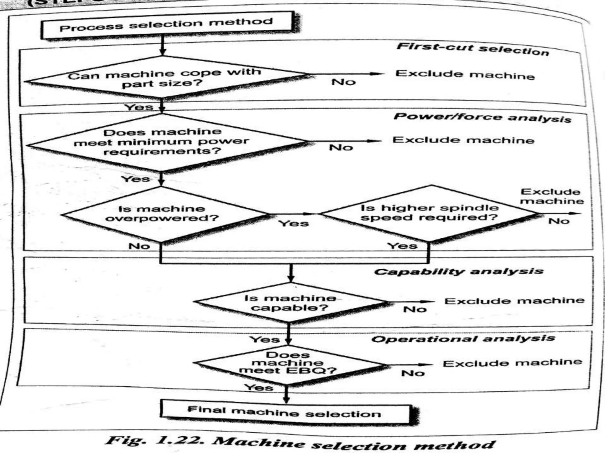
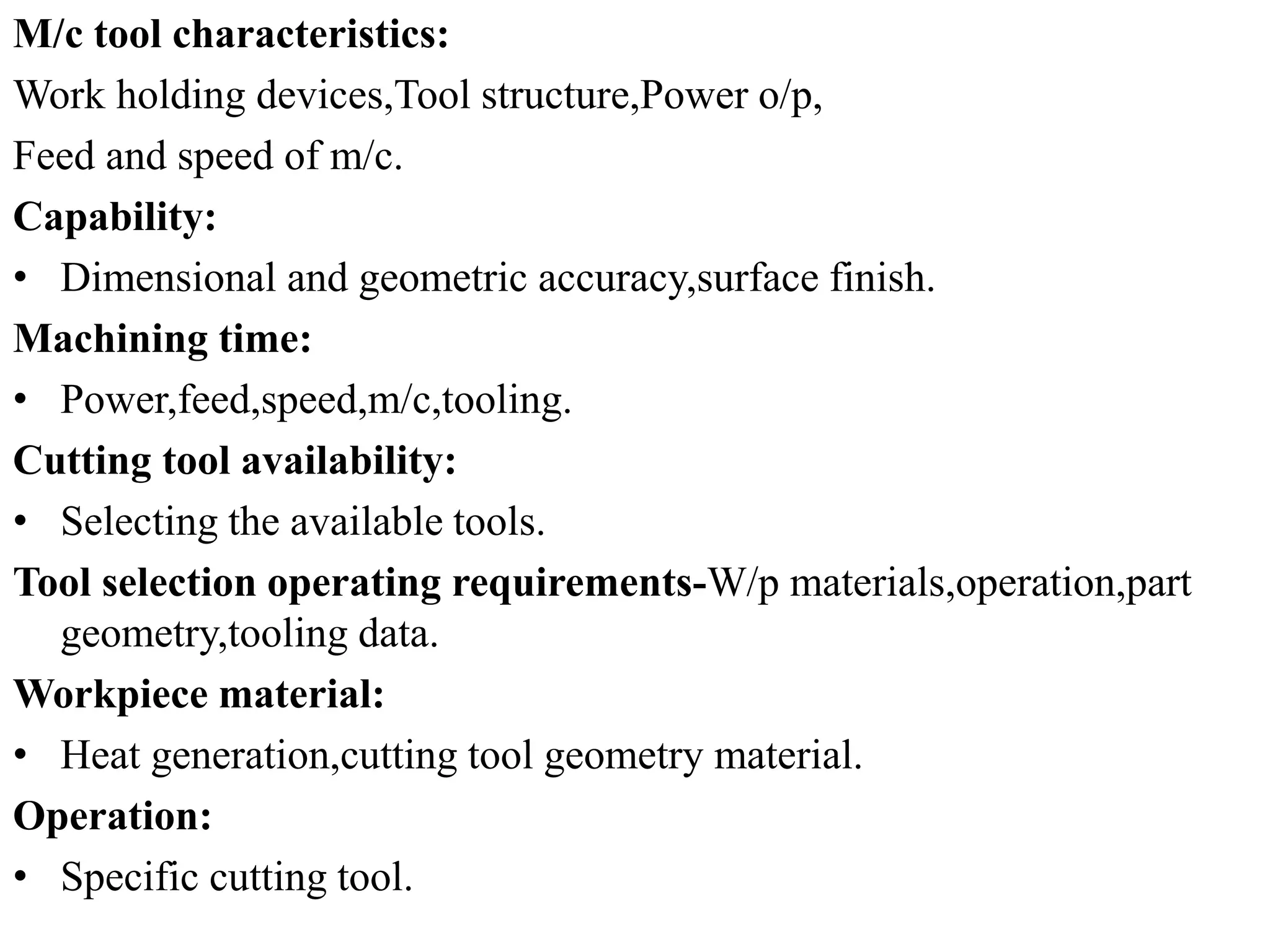
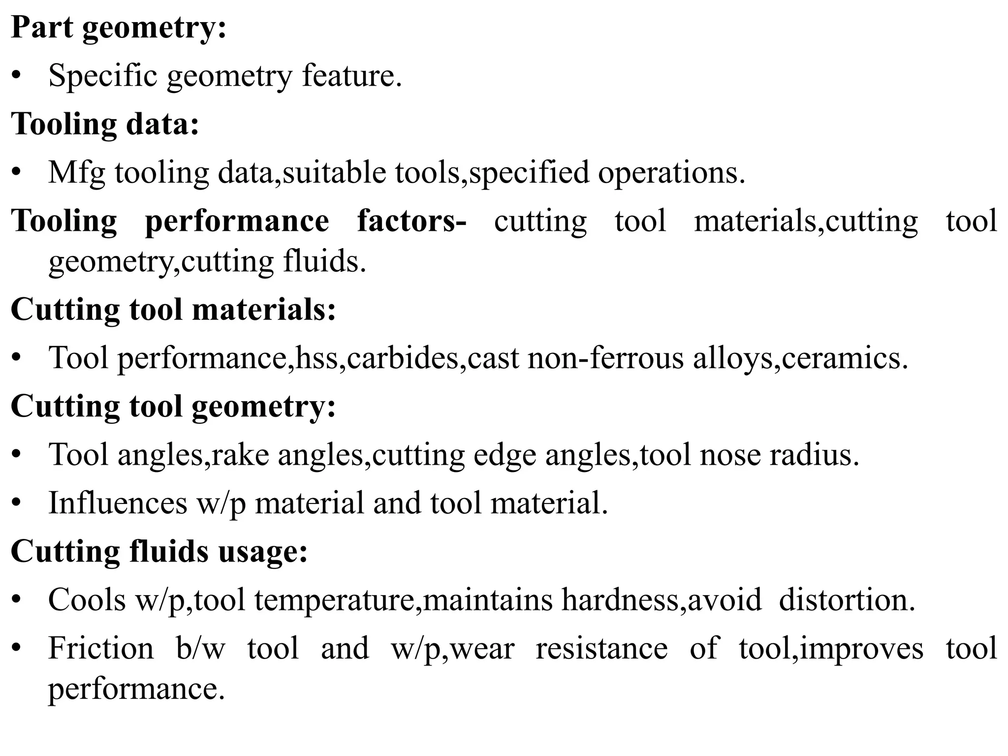
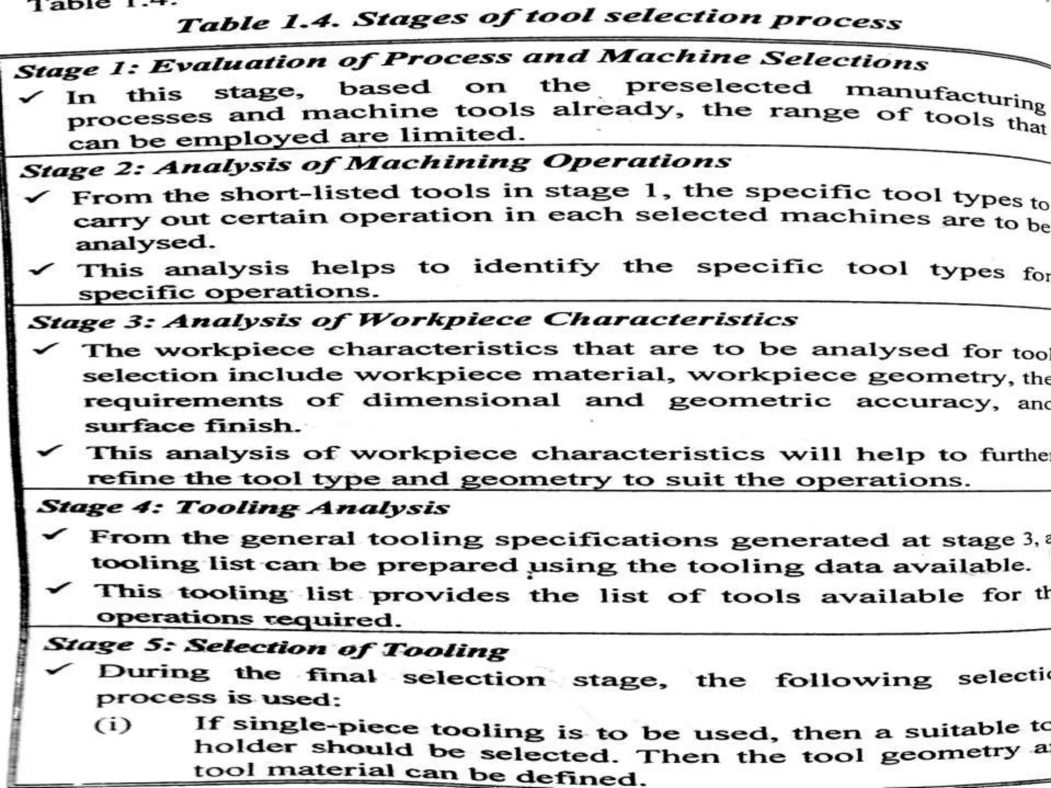
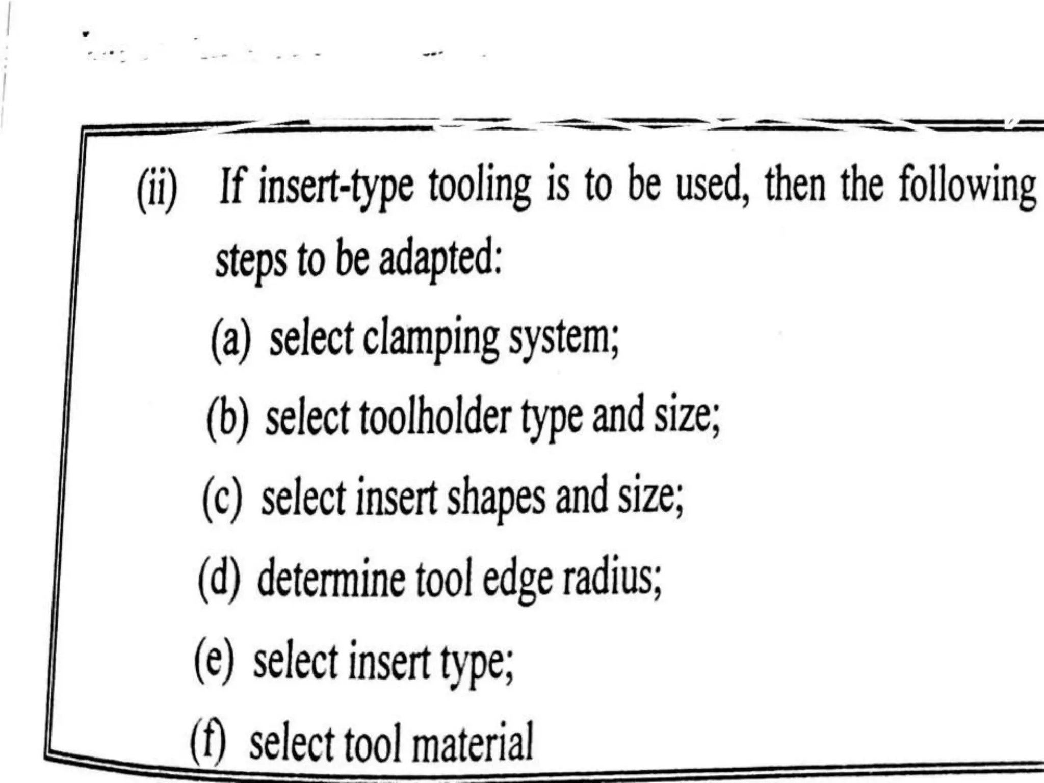
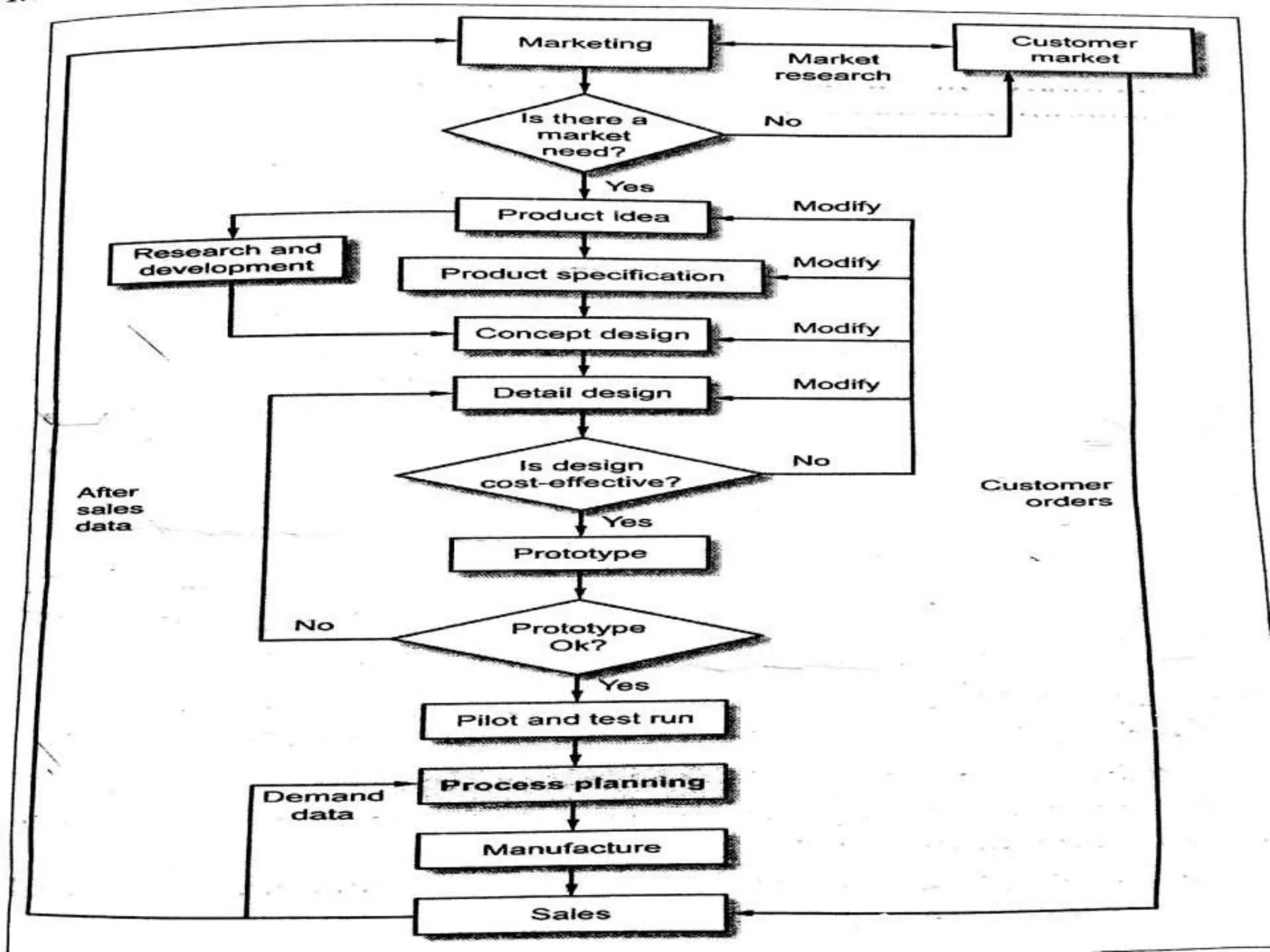
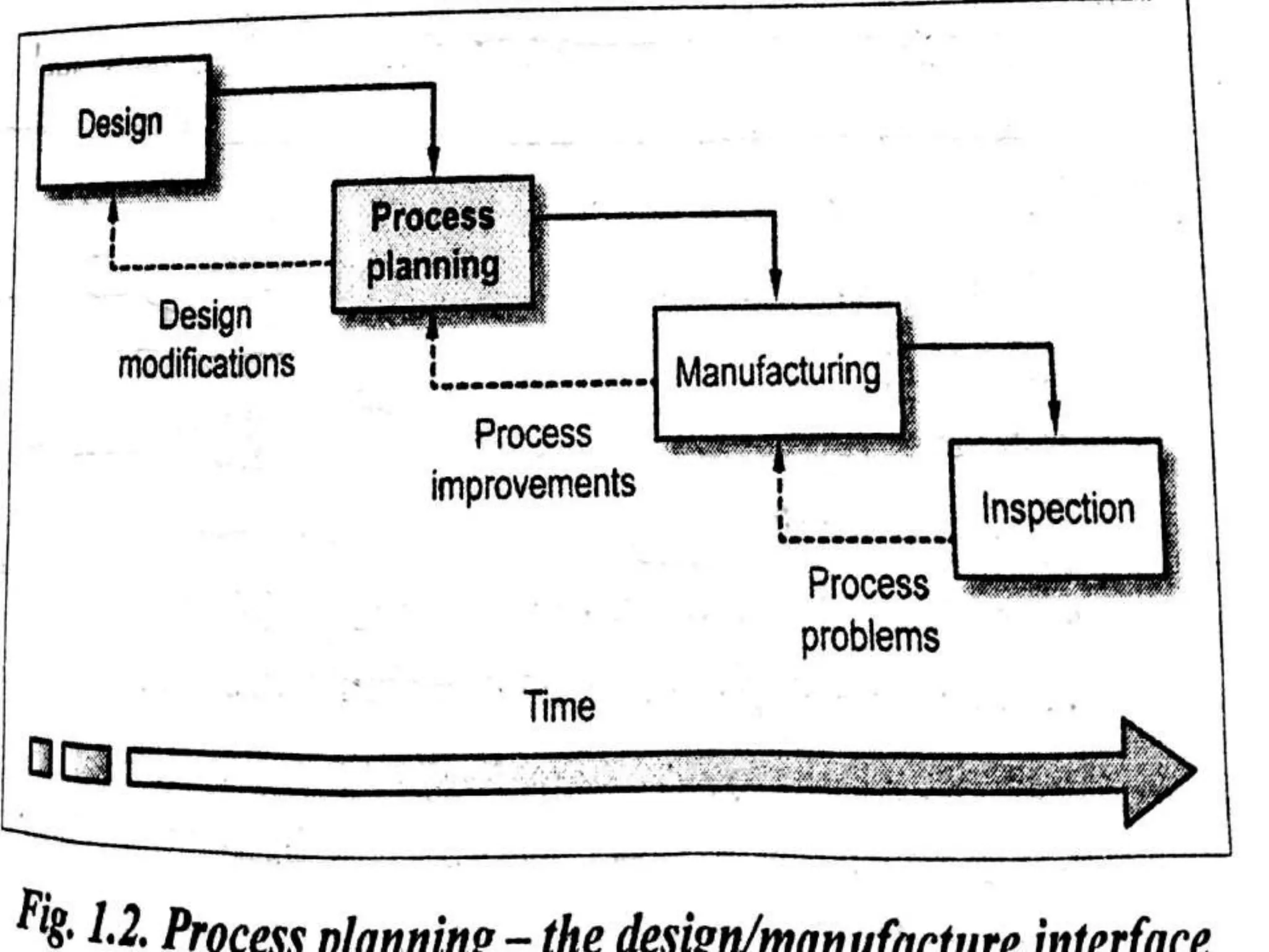
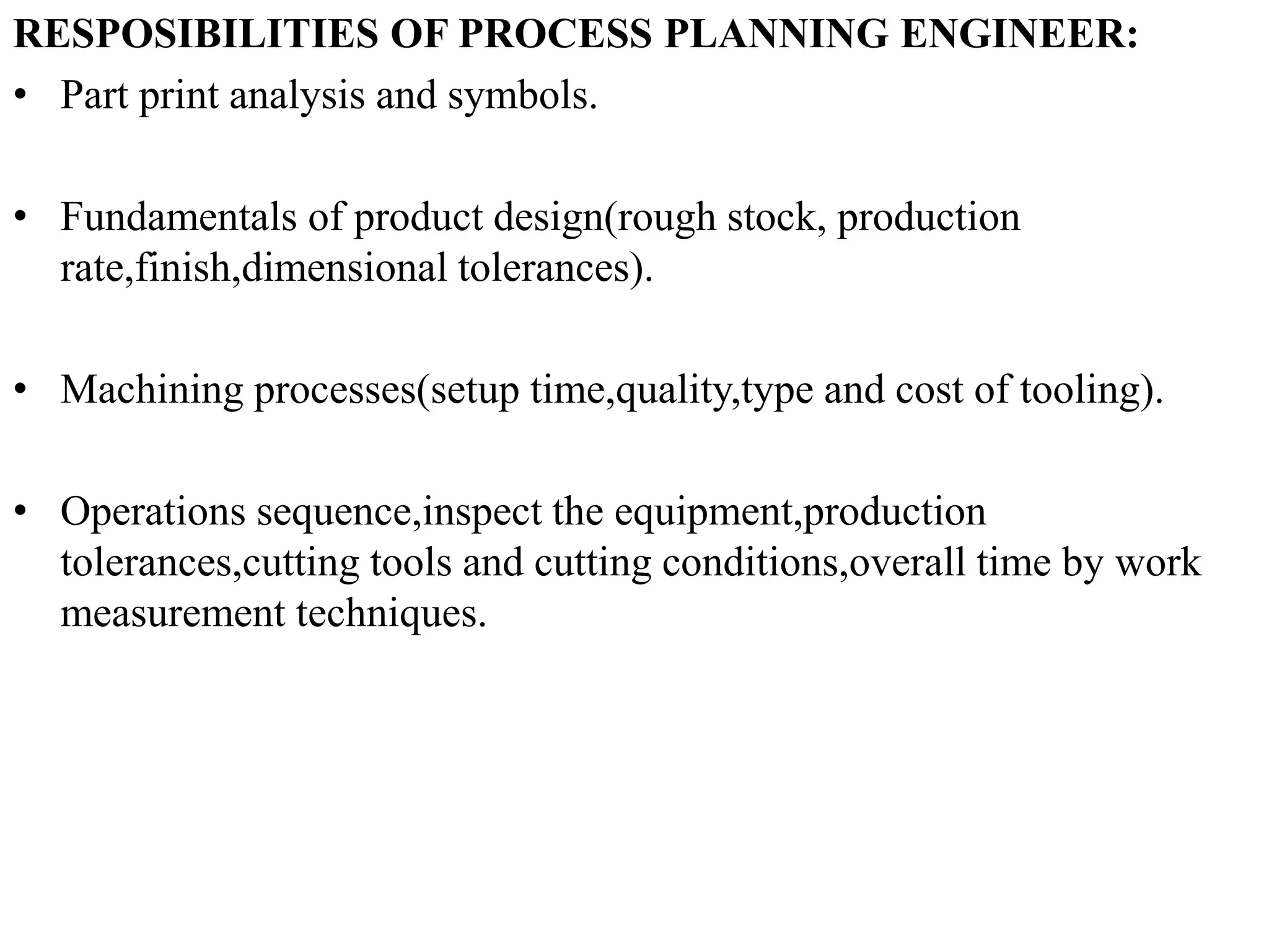
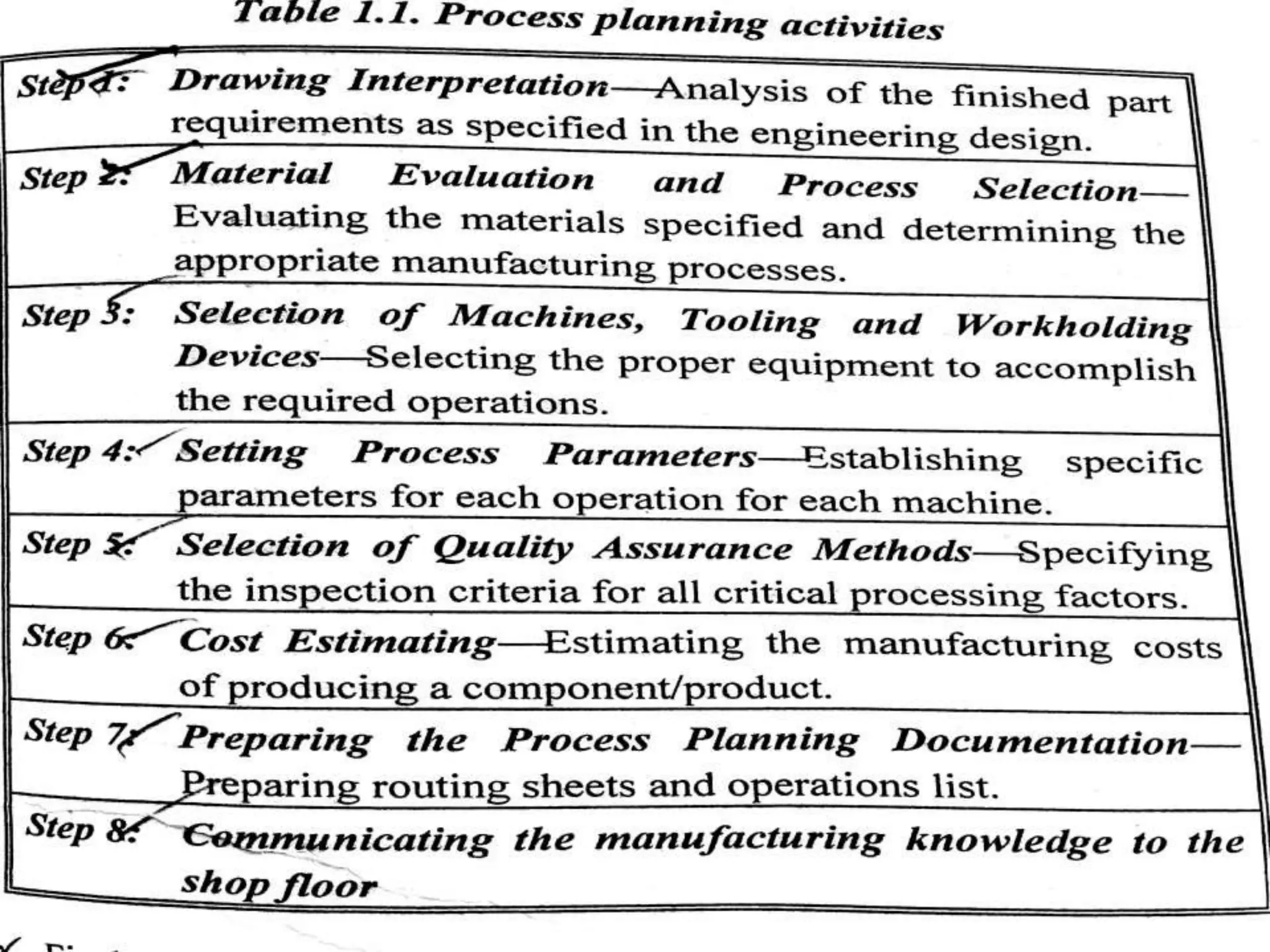
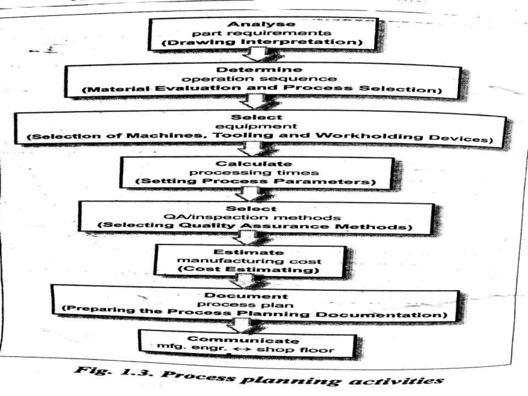
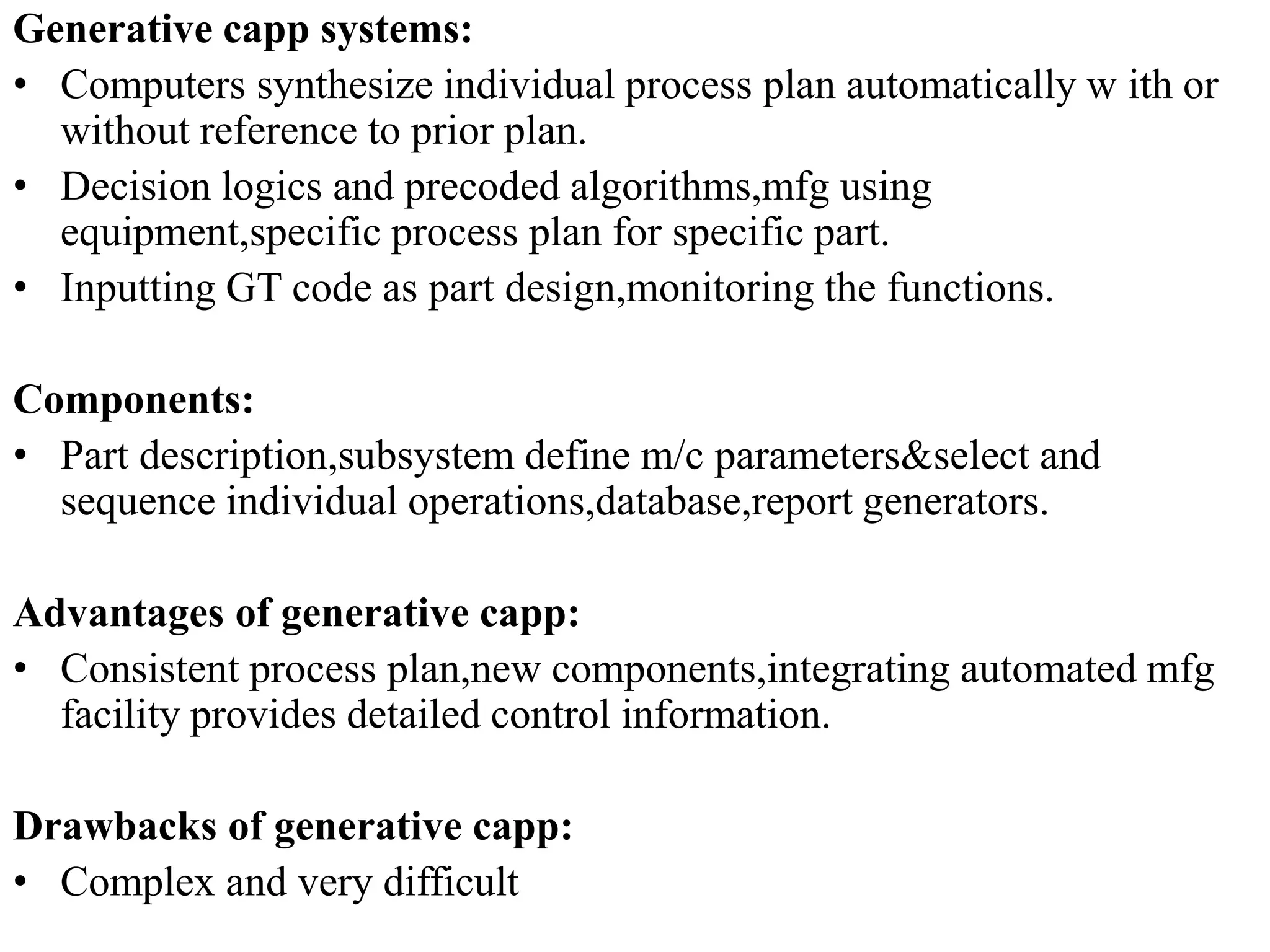
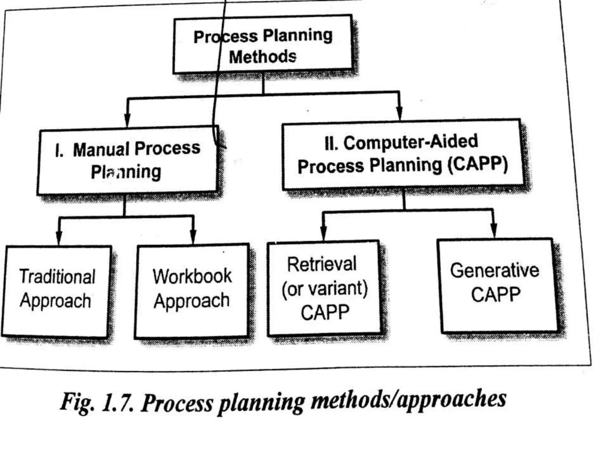
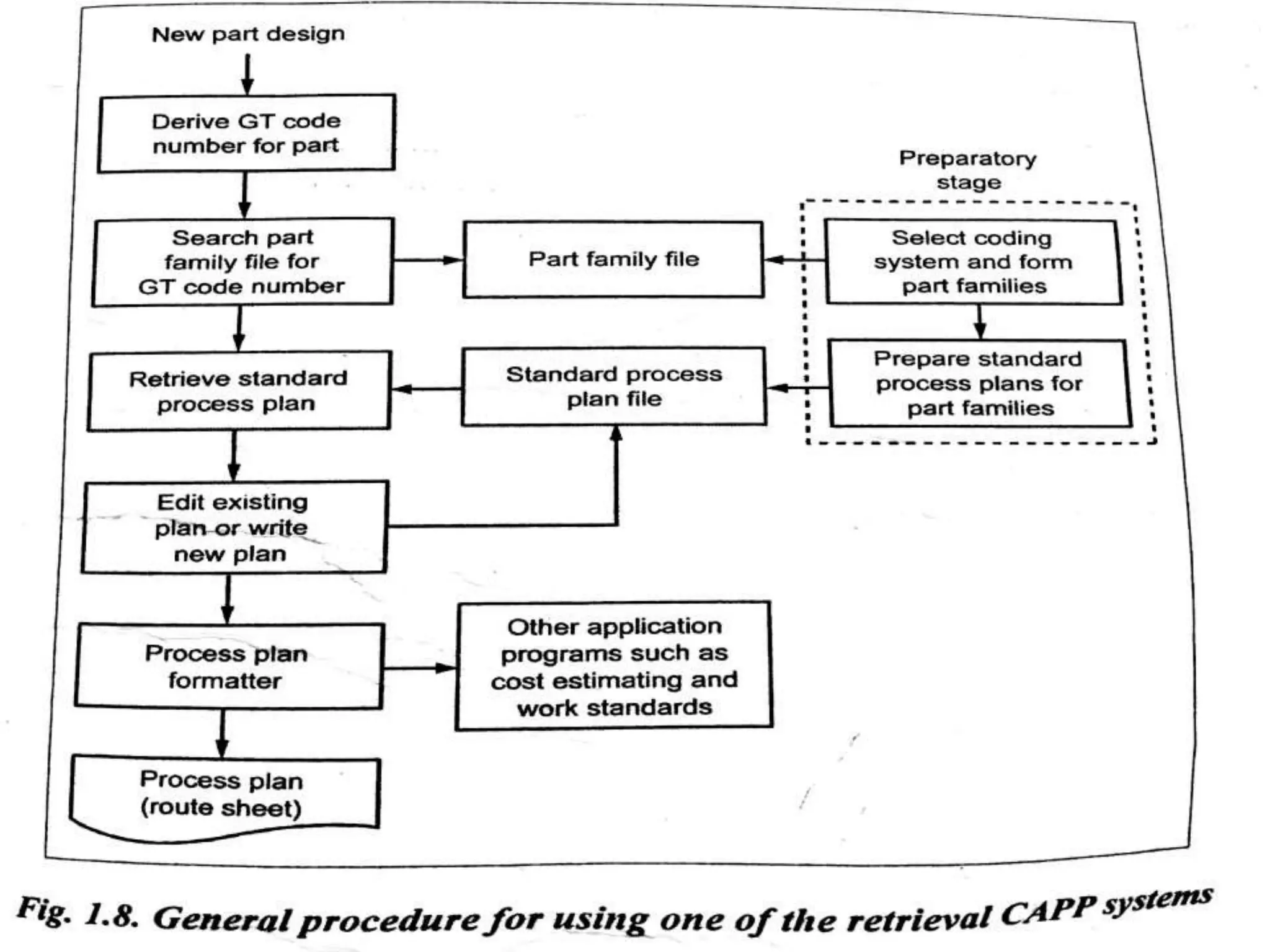
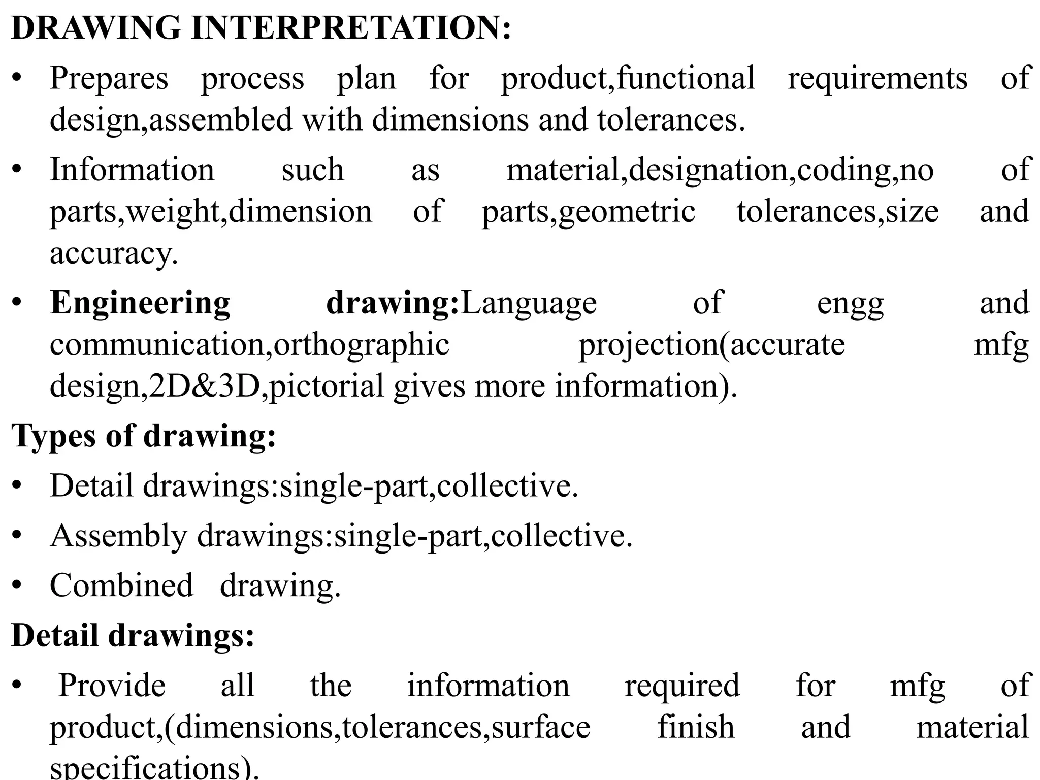
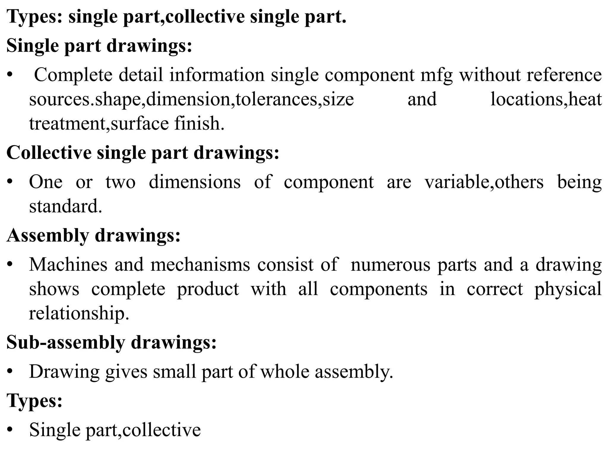
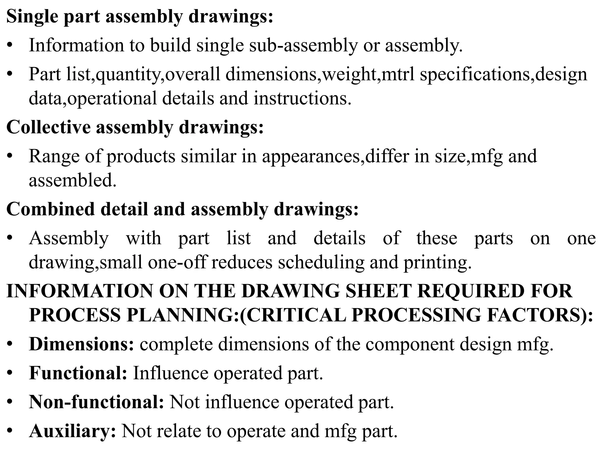
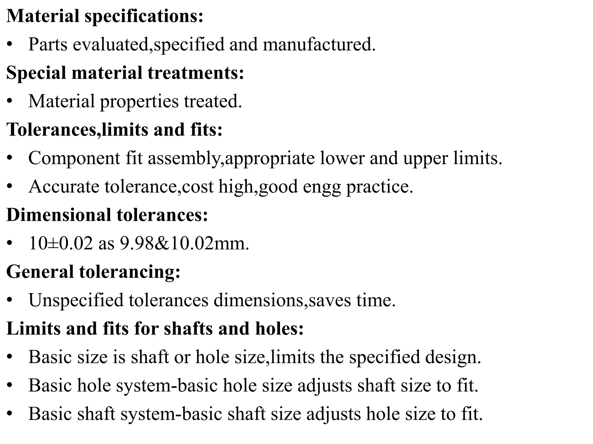
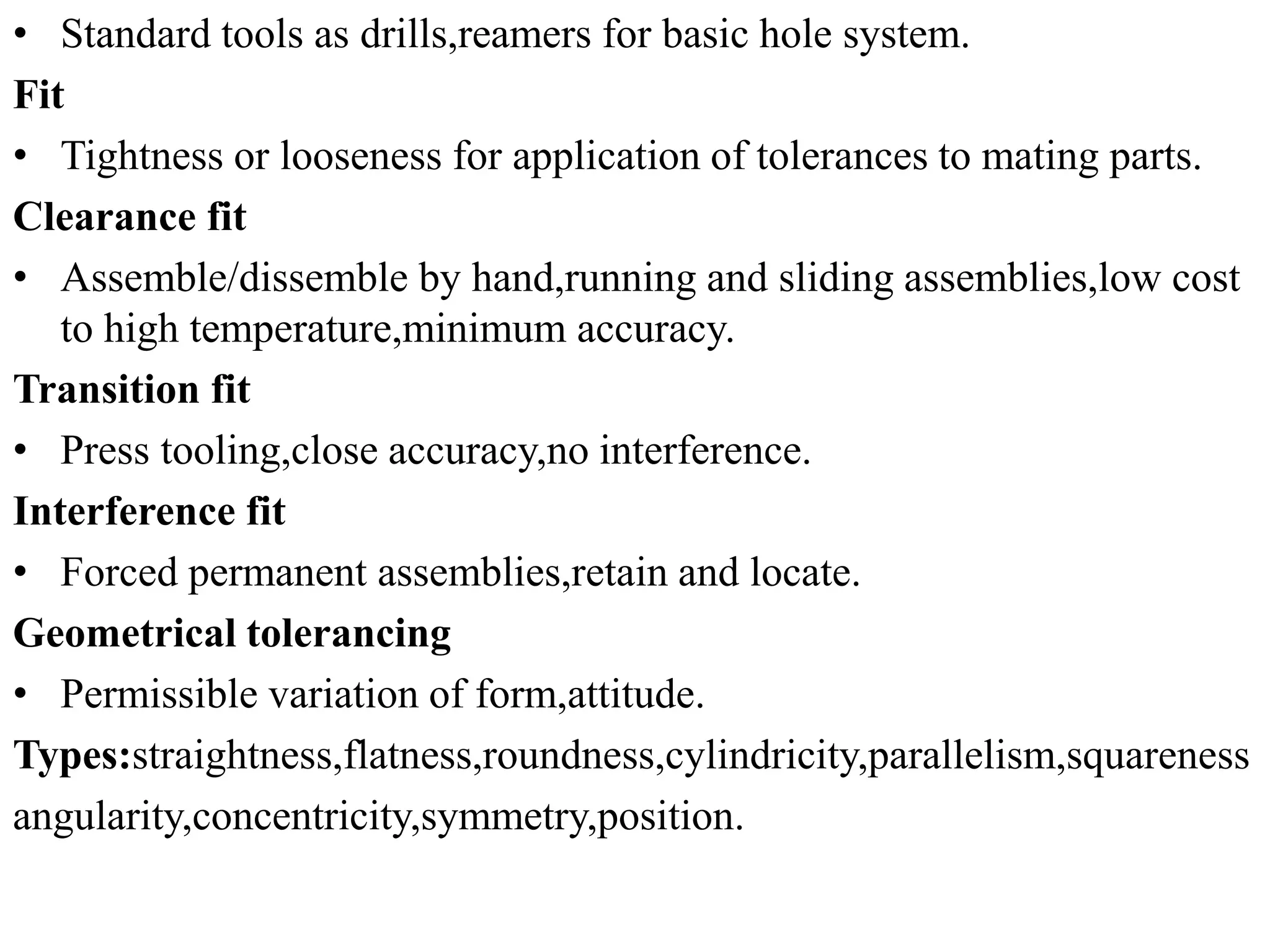
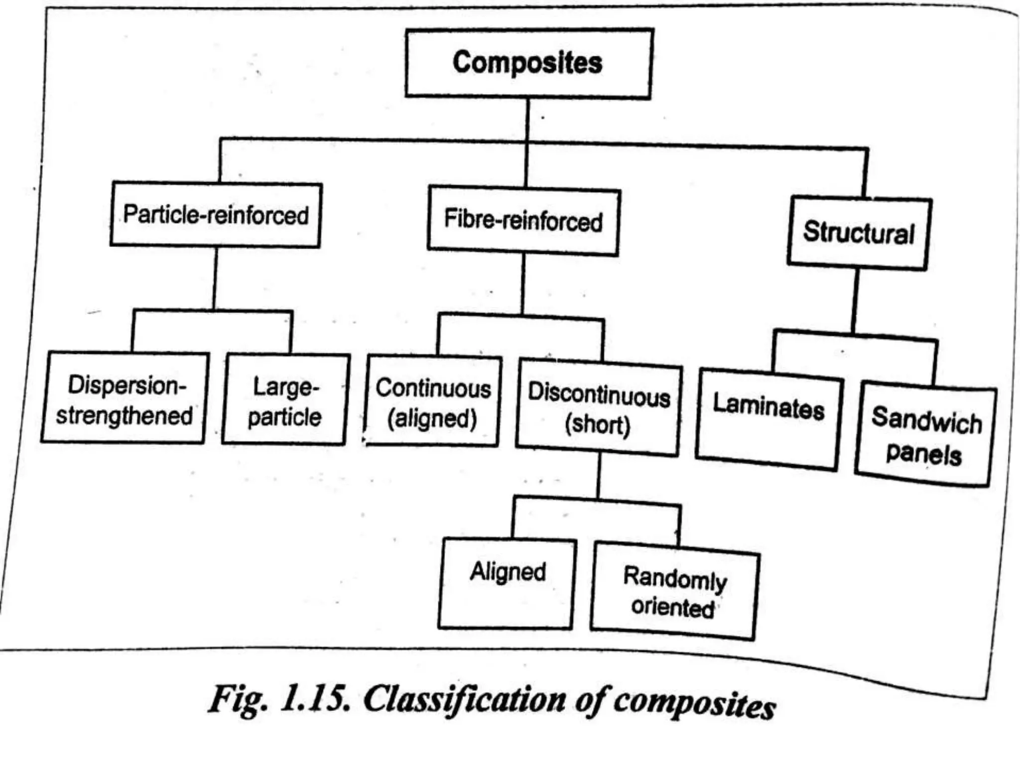
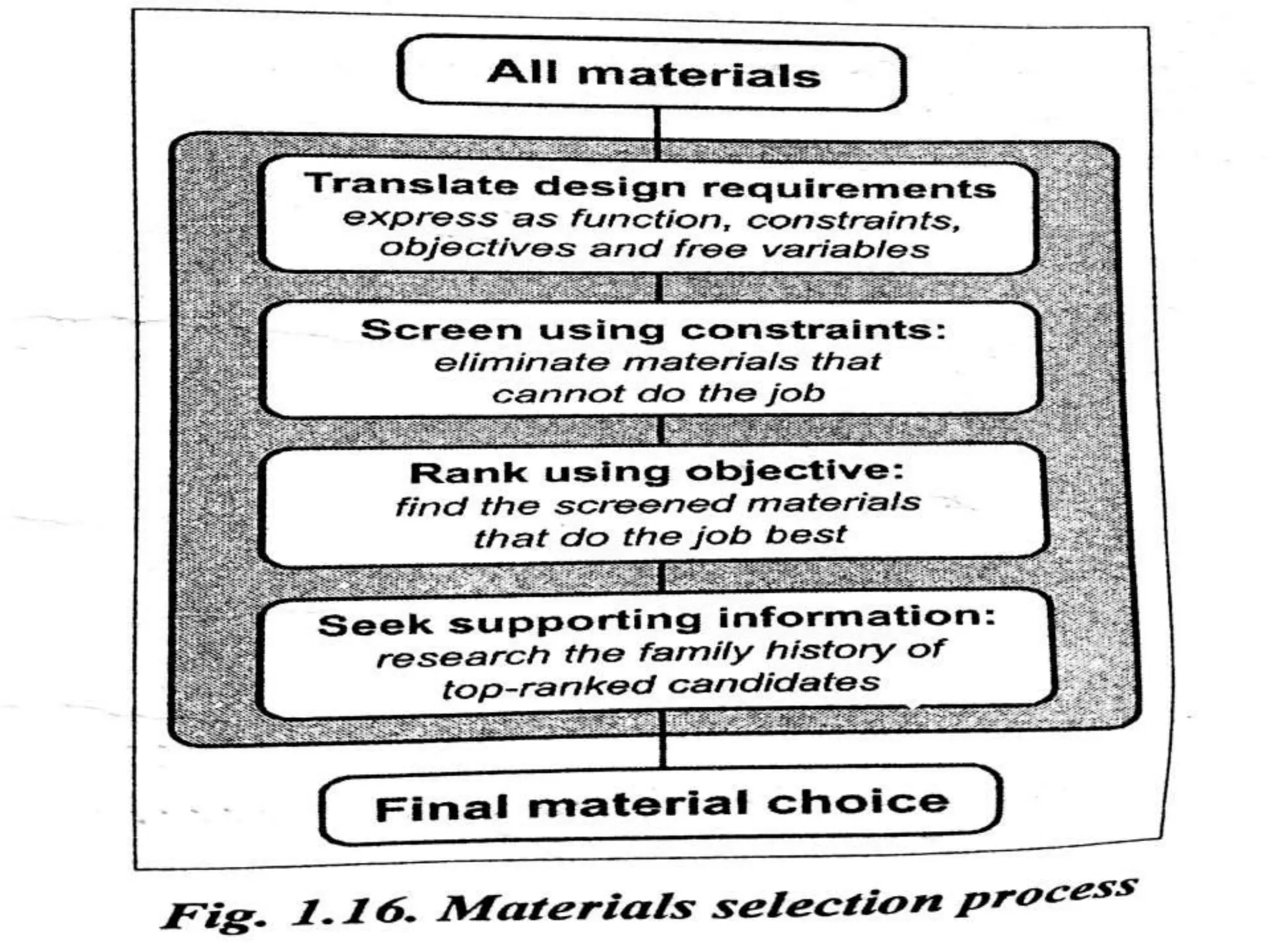
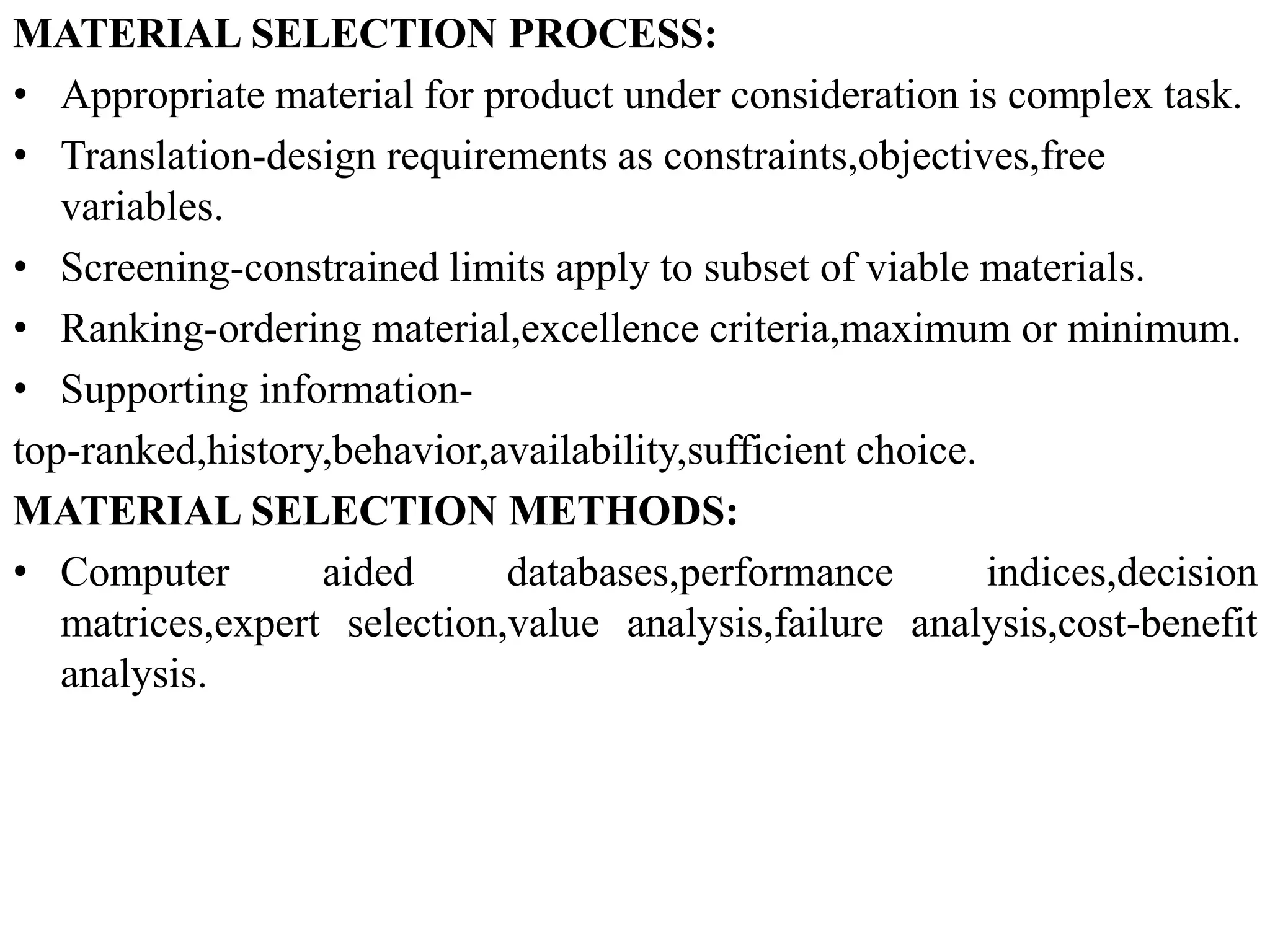
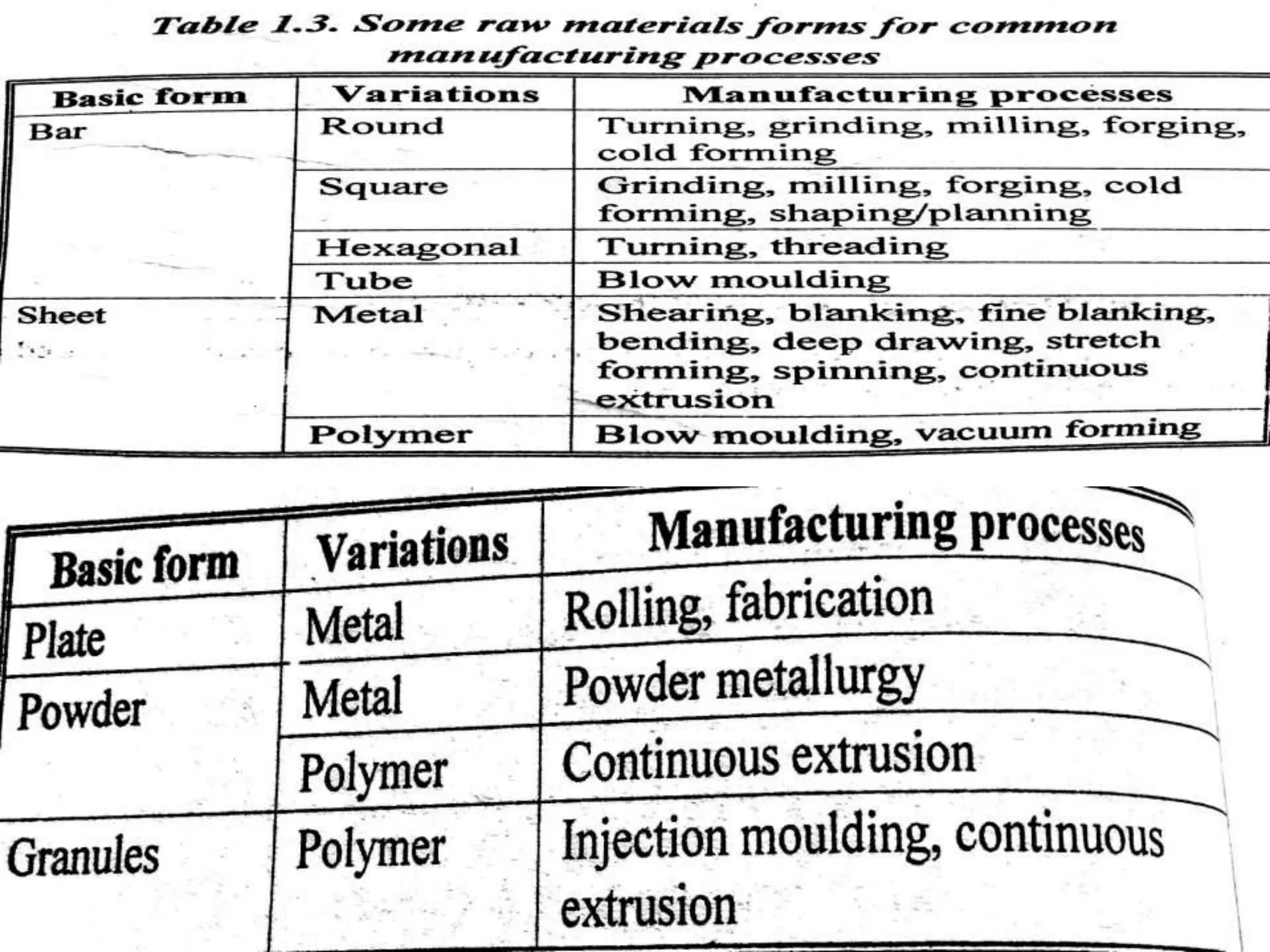
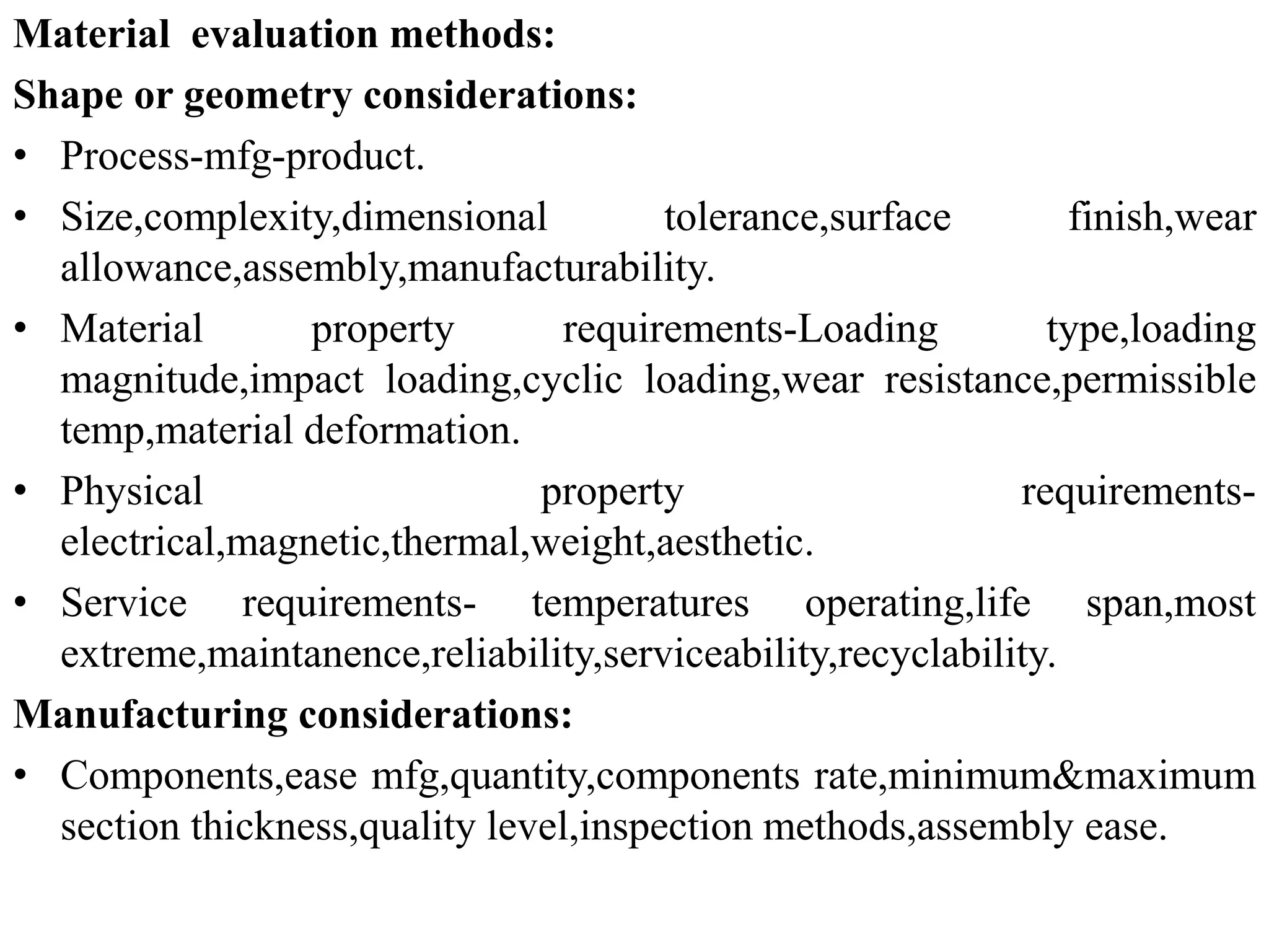
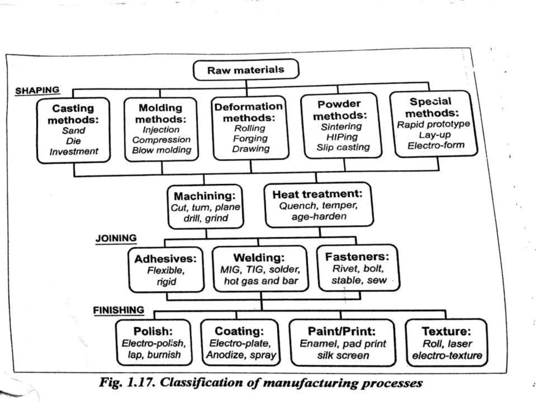
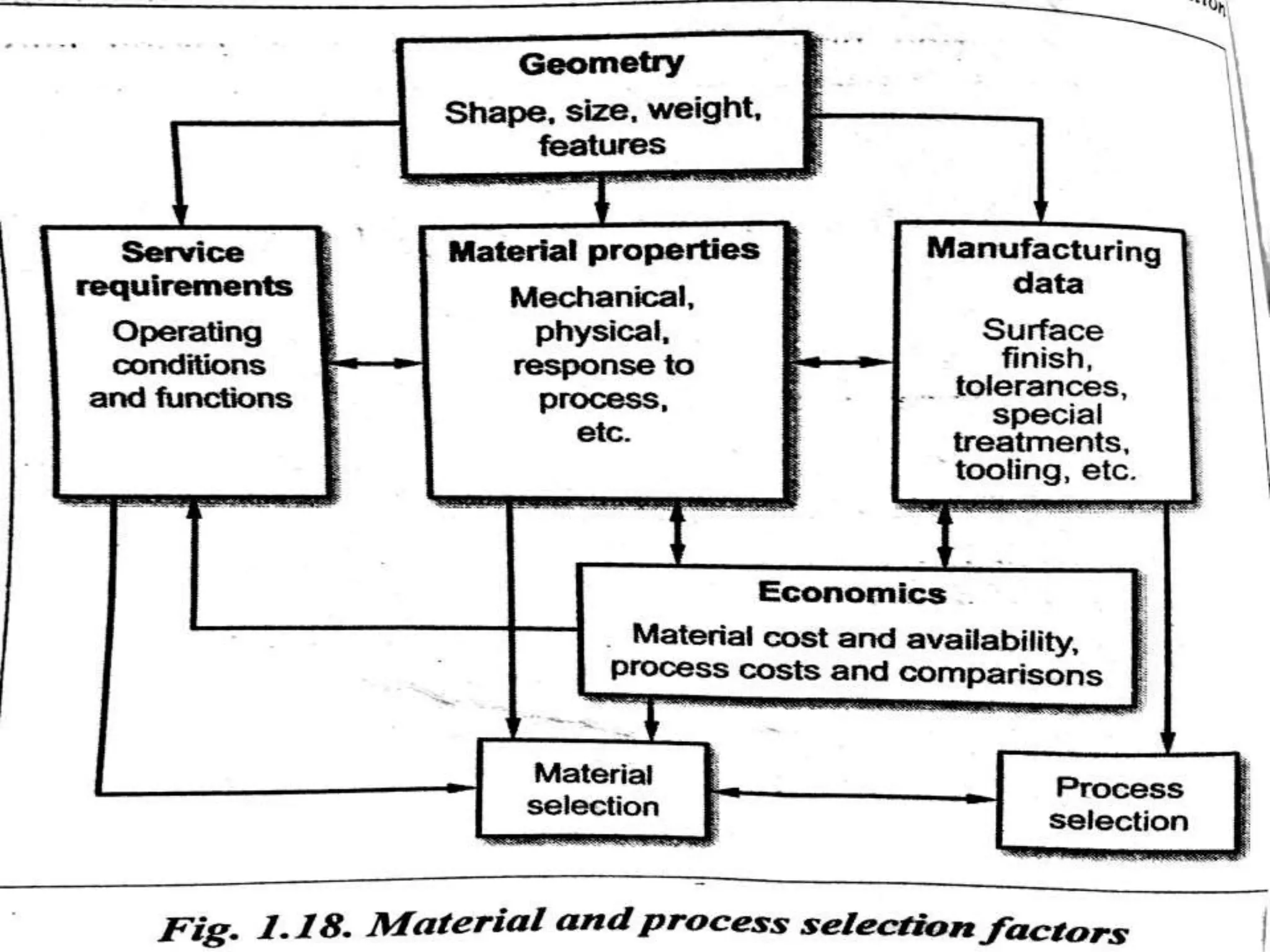
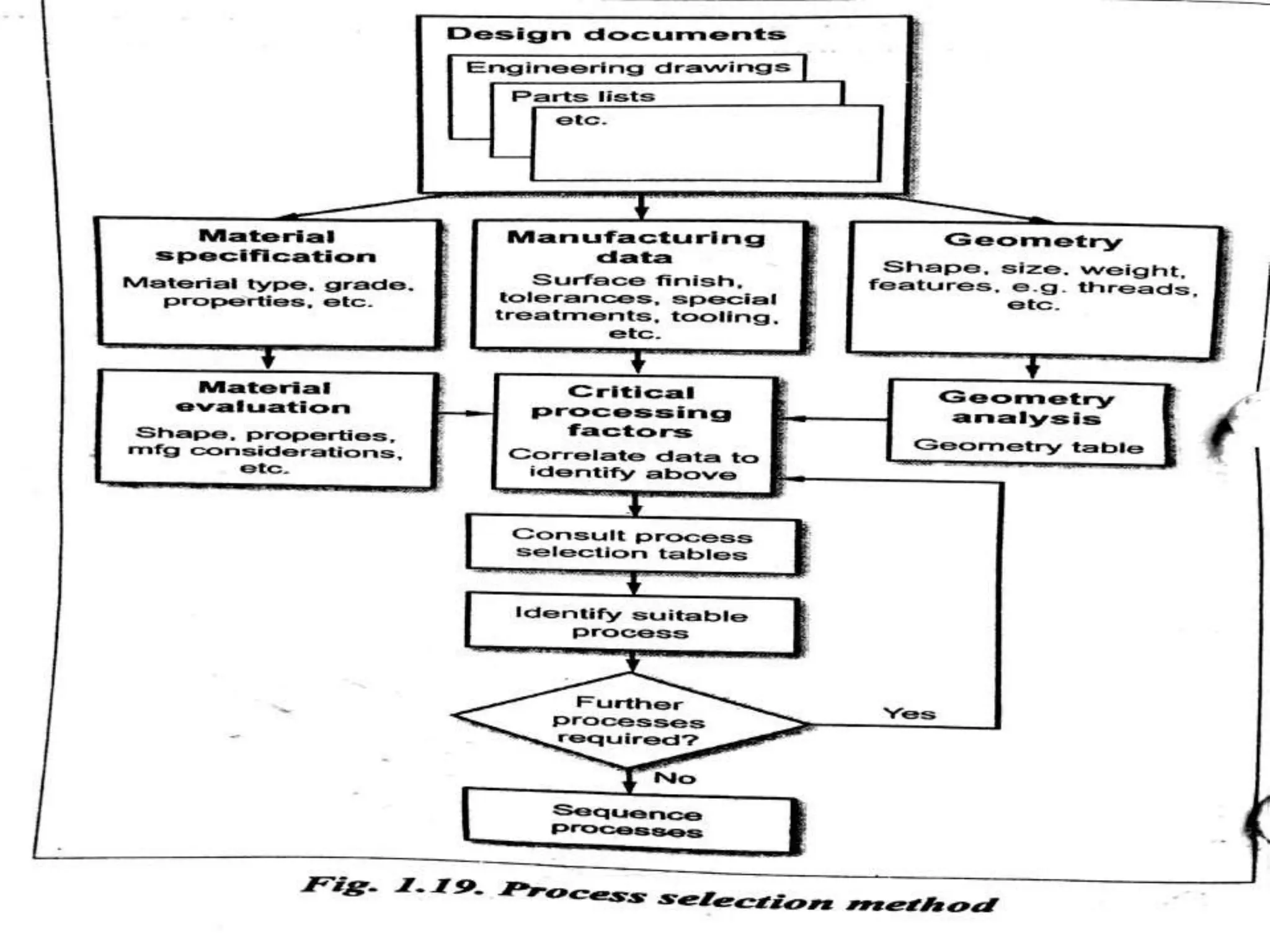
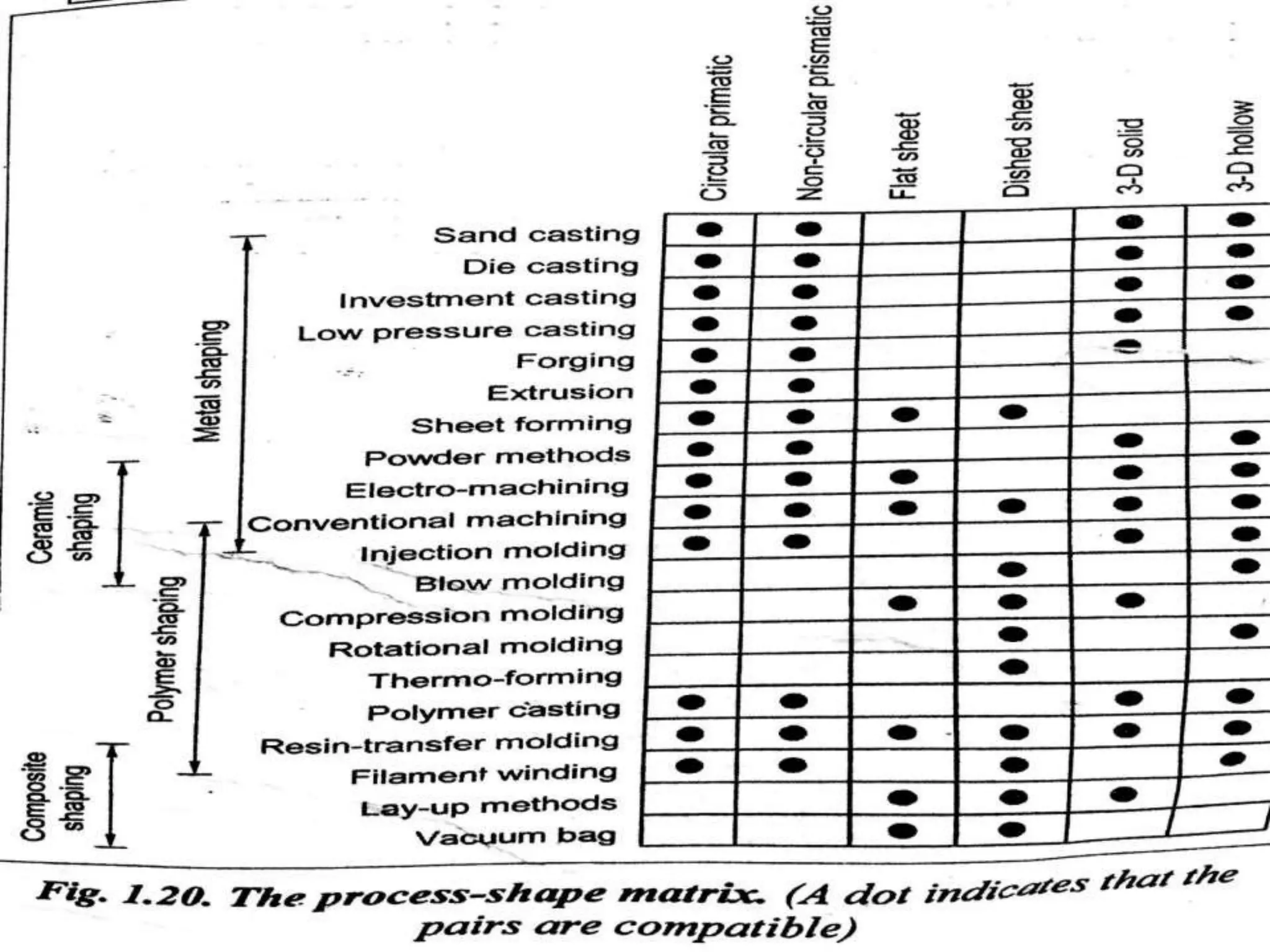
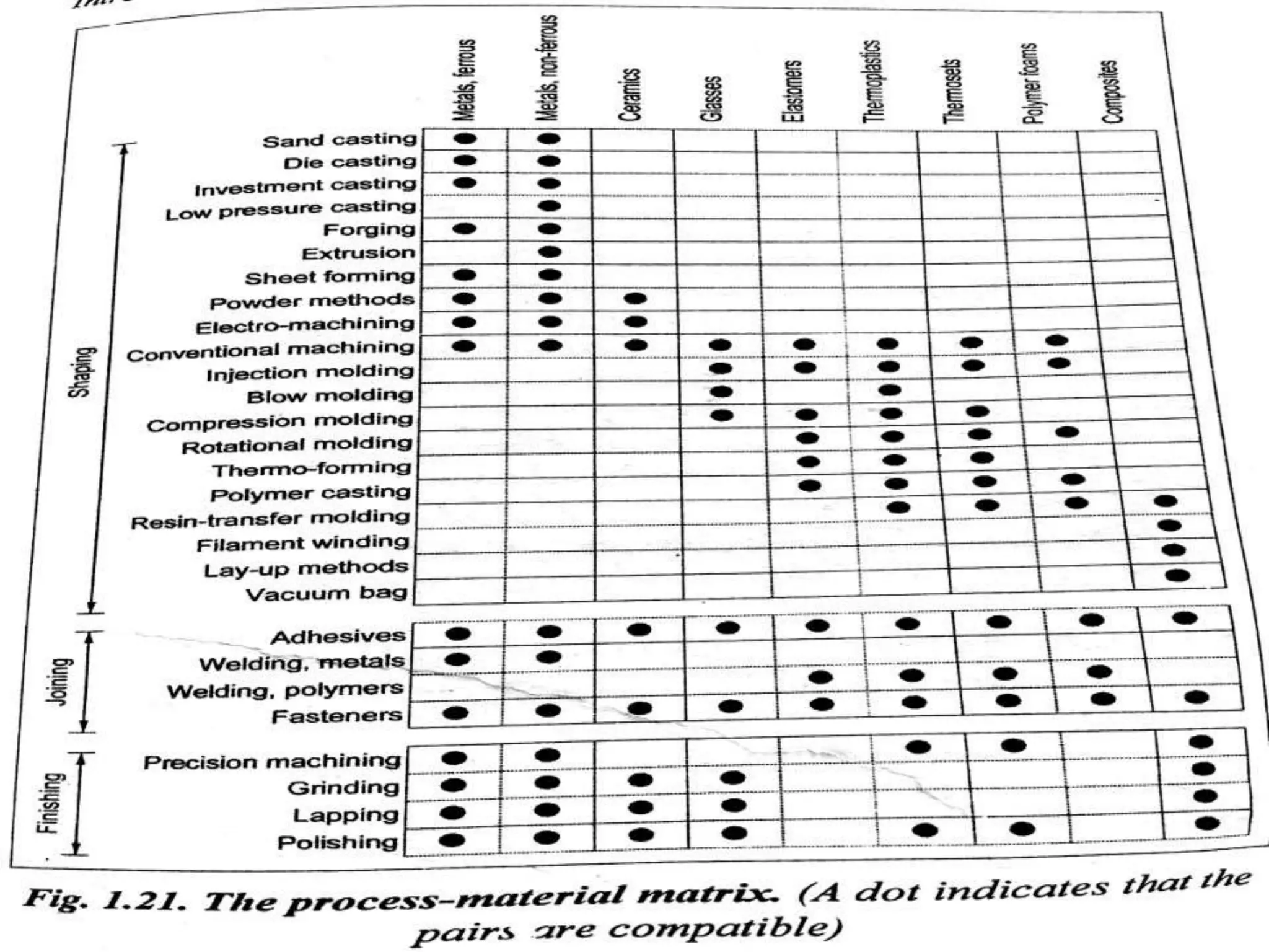
The document discusses process planning which involves determining the manufacturing processes and operations to produce a product economically. It covers key aspects of process planning including drawing interpretation, material selection and evaluation, process selection, selection of equipment and tooling, and process planning documentation. The importance of process planning as the link between design and manufacturing is highlighted.
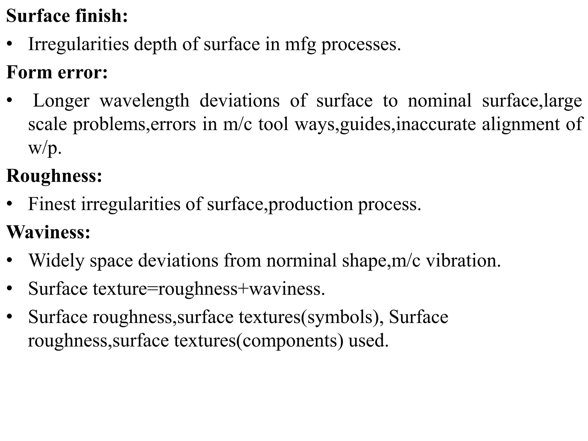
introduction to process planning murugananthanMurugananthan K
Process planning is defined as the conversion of design data into work instructions. It involves systematically determining the most economical and competitive methods to manufacture a product. This includes devising, selecting, and specifying the processes, machine tools, and raw materials needed to convert raw materials into finished products. A process plan contains the route, processes, process parameters, machine and tool selections, fixtures, and machining times. Computer-aided process planning can reduce planning time and costs and increase consistency and accuracy compared to manual planning. Variant planning retrieves standard plans for similar parts, while generative planning automatically synthesizes plans for new parts.
COMPUTER AIDED PROCESS PLANNING (CAPP)KRUNAL RAVAL
Computer-aided process planning (CAPP) helps determine the processing steps required to make a part after CAP has been used to define what is to be made. CAPP programs develop a process plan or route sheet by following either a variant or a generative approach.
This document discusses process planning and cost estimation. It covers topics such as process planning activities like drawing interpretation, material evaluation, process selection, and production equipment selection. It also discusses computer aided process planning approaches like retrieval and generative CAPP. For cost estimation, it covers importance of estimation, types of estimates, elements of estimation, estimating procedure, importance of costing, methods of costing, and calculation of costs.
This document discusses process planning. It defines process planning as systematically determining how a product will be manufactured economically. The objectives are to prepare instructions for manufacturing a product and its parts along with specifications. Process planning activities include analyzing part requirements, determining operation sequences, selecting equipment, calculating times, and documenting plans. Common approaches are manual and computer-aided process planning (CAPP), which can be retrieval-based or generative.
This document provides an overview of Computer Aided Process Planning (CAPP). It discusses the general steps in CAPP, including design input, material selection, and cost estimation. It describes two main approaches to CAPP: variant CAPP, which retrieves and modifies existing process plans; and generative CAPP, which generates new plans using decision logic and algorithms. The advantages of CAPP are reducing time/costs and increasing consistency and productivity. The disadvantages include difficulty maintaining consistency and accounting for all manufacturing factors in variant CAPP, and high initial costs compared to manual planning.
This document discusses process planning and cost estimation for manufacturing. It covers the stages of process planning like drawing interpretation, material selection, process and machine selection. It details the information that can be obtained from engineering drawings for process planning like material, dimensions, tolerances etc. It also discusses factors considered for machine and tool selection like manufacturing process, part geometry, tool materials and cutting fluids. The document provides information on process planning activities from design to cost estimation for production.
This document discusses cost estimation for various manufacturing processes including forging, welding, and foundry. It provides details on estimating material, labor, and overhead costs for each process. For forging, it describes various forging operations and how to calculate material and labor costs. For welding, it defines different joint types and explains how to estimate costs for materials, pre/post welding labor, power, and overheads. For foundries, it outlines the process and provides a brief overview.
Introduction ,FMS Equipment,FMS Layouts ,Analysis Methods for FMS,,advantages of fms,comparison of fms to conventional methods,applications.Benefits of fms.
The document discusses flexible manufacturing systems (FMS). It provides a history of FMS, describing how the concept originated in the 1960s and was first implemented by companies in the US, Germany, Russia, and Japan. It defines an FMS as an automated machine cell consisting of interconnected processing workstations and automated material handling. FMS offers benefits like reduced costs, optimized cycle times, and flexibility to handle different part styles and quick changeovers. It classifies FMS based on the number of machines and describes common components and layouts of FMS. Potential applications and advantages are also outlined, along with challenges associated with implementing FMS.
PPCE unit 3 (ME8793 – PROCESS PLANNING AND COST ESTIMATION) TAMILMECHKIT
UNIT III - INTRODUCTION TO COST ESTIMATION
Importance of costing and estimation –methods of costing-elements of cost estimation –Types of estimates – Estimating procedure- Estimation labor cost, material cost- allocation of over head charges- Calculation of depreciation cost
PPCE unit 2 (ME8793 – PROCESS PLANNING AND COST ESTIMATION )TAMILMECHKIT
UNIT 2 – PROCESS PLANNING ACTIVITIES
Process parameters calculation for various production processes-Selection jigs and fixtures- Selection of quality assurance methods - Set of documents for process planning-Economics of process planning- case studies
Non-traditional machining techniques remove material using various energy sources besides traditional cutting tools. They are divided into mechanical, electrical, thermal, and chemical techniques. Non-traditional techniques are needed for hard or complex materials, and can machine intricate shapes and deep holes. Selection depends on the part geometry, material properties, machining capabilities, and cost effectiveness. While more expensive initially than traditional techniques, non-traditional machining offers higher precision, surface finish, and ability to machine difficult materials.
Preparing cost estimate for manufactured products.ppt by-aragaw gebremedhinAragaw Gebremedhin
Here are the solutions to the examples provided:
1) A) Prime cost (PC) = Direct material cost + Direct labour cost = $160 + $200 = $360
B) Factory cost (FC) = Prime cost + 35% of prime cost = $360 + 35% of $360 = $360 + $126 = $486
C) Total production cost (TC) = Factory cost + 20% of factory cost = $486 + 20% of $486 = $486 + $97.20 = $583.20
D) Selling price = Total cost + 10% of total cost = $583.20 + 10% of $583.20 = $583.20 + $58.32
The document discusses process planning and cost estimation for manufacturing. It covers topics like process planning activities, documentation, computer-aided process planning, material selection and evaluation, process and machine selection methods, tooling selection, and drawing interpretation. The key aspects of process planning include designing the product, planning the manufacturing processes, and linking design to manufacturing.
Process parameters calculation for various production processes-Selection jigs and fixtures election of quality assurance methods - Set of documents for process planning-Economics of process planning.
The document discusses process planning, which involves selecting and sequencing manufacturing processes and operations to transform raw materials into finished components. It covers manual and computer-aided process planning methods. The key steps in manual process planning are interpreting drawings, selecting processes and operations, choosing tools and equipment, and documenting the plan. Computer-aided process planning can retrieve existing plans or generate new optimized plans. Important considerations in process planning include equipment selection, tooling selection, and interpreting engineering drawings and specifications.
GT Definition,Implementing Group Technology (GT),four methods GT, 1.OPTIZ PARTS CLASSIFICATION AND CODING SYSTEM,2.MICLASS coding system ,CODE MDSI System,BENEFITS OF GROUP TECHNOLOGY and limitations.
Unit 1-ME8691 & COMPUTER AIDED DESIGN AND MANUFACTURINGMohanumar S
This document provides an introduction and syllabus for a course on computer aided design and manufacturing (CAD/CAM). It discusses the product design and manufacturing processes, including sequential and concurrent engineering models. It also describes CAD systems and computer graphics technologies used to design products digitally. This includes topics like 2D and 3D coordinate systems, geometric transformations, line drawing algorithms, and viewing transformations. The goal of the course is to introduce students to how computer technologies are used in the product design and manufacturing fields.
Flexible manufacturing systems (FMS) consist of interconnected computer-controlled machines and automated material handling systems. An FMS allows for mixed production and variation in parts, assembly, and processes. It includes processing workstations, an automated transport and storage system, and a computer control system that coordinates the activities. FMS provides benefits like decreased lead times, increased throughput and quality, and reduced costs. However, FMS implementation requires substantial investment and planning to address technological and coordination challenges.
1. Numerical control (NC) systems were developed to automate machine tools using programmed sequences of instructions to control machine motions and functions.
2. NC systems use a machine control unit to read numerical input from a program and translate it into mechanical motions of the machine tool.
3. Modern computer numerical control (CNC) systems provide even greater flexibility and precision by using computers to generate and process NC programs and control machine tools.
The document discusses numerical control (NC) machine tools. [1] NC refers to controlling manufacturing operations through coded numerical instructions inserted directly into machine tools. [2] John T. Parsons is considered the inventor of NC in the 1940s when he used punched cards to control machine tool movements. [3] A NC system consists of a program of instructions, controller unit that interprets the program and controls the machine tool.
Unit 4-ME8691 & COMPUTER AIDED DESIGN AND MANUFACTURINGMohanumar S
This document provides information on numerical control systems and computer numerical control (CNC) systems. It defines numerical control and describes traditional NC, CNC, and DNC systems. It discusses the basic components of NC systems including software, machine control units, and machine tools. It also covers CNC machine construction, driving systems, tooling systems, applications, advantages, and disadvantages of NC and CNC machines. Finally, it discusses topics like part programming fundamentals, coordinate systems, canned cycles, and micromachining.
Water jet machining uses a high-pressure stream of water to cut materials. It is a cold cutting process that produces no heat-affected zones. The water jet travels at supersonic speeds and erodes material when the local pressure exceeds the material's strength. Key components include a hydraulic pump to pressurize water, an intensifier to further pressurize it, and a nozzle to direct the jet. It can cut a variety of materials and offers advantages over other cutting methods like reduced burrs, flexibility of cutting complex shapes, and not producing heat or fumes. However, it is not suitable for high-volume production.
Group technology _ flexible manufacturing system_supply chain managementPankaj Kumar
Group Technology (GT) is a manufacturing philosophy that groups components together based on their geometric similarity or manufacturing process. GT aims to maximize output, reduce lead times and material handling, and reduce scrap. Flexible Manufacturing Systems (FMS) use computer-controlled machines interconnected by automated material handling to improve utilization rates, reduce floor space needs, and lower manufacturing lead times. Supply Chain Management (SCM) coordinates the flow of materials, information, and finances between suppliers, manufacturers, distributors, and consumers with the goal of delivering the right products in the right quantities at the right locations and times.
Chapter 3 CNC turning and machining centersRAHUL THAKER
This document discusses CNC turning and machining centers. It describes turning as a machining process using a lathe where the tool moves parallel to the workpiece axis to remove material. CNC lathes are replacing older lathes. Milling involves using rotating cutting tools to produce flat and helical surfaces. Machining centers are classified as vertical, horizontal, or universal depending on the spindle orientation. Machining centers have automatic tool changers and may have automatic workpiece positioners or pallet changers to reduce non-productive time during machining operations.
This document discusses deburring processes. It defines burrs as sharp edges created during cutting and stamping operations that can cause assembly and safety issues. Deburring is the process of removing burrs, typically through filing, sanding, or newer techniques. The document outlines several common mechanical deburring processes like cutting, power brushing, bonded abrasives, mass finishing and abrasive blasting. It also discusses less common thermal deburring using heat and electro-chemical deburring which dissolves burrs using electrolysis. The goal of deburring is to prepare metal or wood surfaces for further finishing or assembly.
INTELLIGENT DECISION MAKING FOR REACTIVE SCHEDULING IN FMSJyotiraman De
The document discusses product and service design prints, computer aided process planning (CAPP), and the variant and generative approaches to CAPP. It defines product and service design prints as defining the characteristics and concepts of products and services. It then defines CAPP as using computers to assist process planners in determining the methods to manufacture parts from initial to final form. The variant approach selects generic process plans using group technology codes, while the generative approach automatically synthesizes process plans without human intervention using databases and knowledge bases.
This document summarizes computer aided process planning. It discusses that process planning converts design information into manufacturing instructions to effectively produce products. It then describes different approaches to computer aided process planning including manual process planning, variant approach using group technology and part coding, and generative approach. The variant approach retrieves standard plans while the generative approach automatically generates new plans by matching part geometry to manufacturing capabilities. Overall, computer aided process planning aims to reduce time, labor, costs and improve precision and understanding of manufacturing processes.
Process planning involves determining the optimal methods for manufacturing a product economically and competitively. It includes devising and selecting processes, machine tools, and specifying parameters to convert raw materials into finished goods. Process planning results in a process plan (or route sheet) that details the specific operations, machines, tools, fixtures, processing times, and sequence of operations required for production. Computer-aided process planning (CAPP) utilizes computer software and databases to automate the generation of process plans and has advantages over manual process planning such as increased productivity, reduced costs, and more consistent plans.
The document discusses process planning, which involves translating design requirements into manufacturing process details. It describes process planning as a bridge between design and manufacturing. The document then discusses several key aspects of process planning including analyzing part requirements, selecting materials and operations, interpreting designs, choosing equipment, and creating work instructions. Finally, it compares manual and computer-aided process planning (CAPP) methods, with CAPP helping to reduce time/costs and increase consistency and accuracy compared to experience-based manual methods. CAPP approaches include variant, generative, and automatic planning.
Computer integrated manufacturing (CIM) aims to integrate all functions related to manufacturing, from order receipt through production to shipment, using computer and communication technologies. CIM encompasses CAD/CAM functions like product design, process planning, and NC programming, as well as business functions like order entry, production planning and control, and inventory management. The goal is to automate information flow and the transition from design to manufacturing. Techniques covered include CAD, CAM, CAPP, CAE, FMS, JIT, MRP and LAN. JIT production minimizes waste like work-in-progress inventory by delivering components just when needed downstream.
This document provides an introduction to CAD/CAM/CAE. It begins by defining each term: CAD assists in computer-aided design, CAM plans and controls manufacturing through computer interfaces, and CAE applies computer analysis to engineering components. It then discusses how 3D CAD data can be read by CAM software to generate tool paths for CNC machining. The document also defines computer-integrated manufacturing (CIM) as the total integration of CAD/CAM and business operations using computer systems. It provides an overview of how CAD, CAM, and CAE are applied within the overall product design and manufacturing cycle.
This document discusses optimization and tooling requirements for CNC machines. It covers optimization of machining costs and production rates based on cutting speed. It also discusses the role of computerized optimization systems at different levels. For tooling requirements, it describes various tool holding systems like modular quick change systems, tool holder spindle connections, cutting tool clamping systems, milling cutter drivers, side lock chucks, collet chucks, hydraulic chucks, and milling chucks. It also discusses tool magazines and automatic tool changers.
Production planning & control - descriptive type question module -wise for upcoming Mumbai university exam - Mechanical Engineering - Learn with GeekAlign
Group technology (GT) is a manufacturing philosophy that groups similar parts together based on their design attributes and manufacturing processes. This allows parts to be processed in dedicated machine cells. Key benefits include reduced setup times, work-in-process inventory, and material handling due to processing parts within cells rather than across the entire factory. Implementing GT involves substantial tasks like identifying part families and rearranging production machines into cells.
Computer aided process planning (CAPP) involves using computer software to generate manufacturing process plans. CAPP aims to standardize and optimize processes to improve productivity and reduce costs. Variant CAPP systems retrieve existing process plans for similar parts, while generative CAPP systems automatically generate new plans without human input. The main benefits of CAPP include eliminating errors, reducing time and costs, and facilitating integration with CAD/CAM systems.
Production planning and control involves three main stages: planning, operation, and control. Planning determines what to produce, how to produce it, where, when, who will produce it, and how much to produce. Operation is the execution of the production plan. Control involves comparing actual results to production standards and taking corrective actions if needed. Key factors that determine the appropriate production planning and control system include the production volume, nature of the production process, complexity of operations, and magnitude of operations. The system aims to maximize efficiency, utilization of resources, and reliable delivery while minimizing costs and maintaining product quality.
Introduction to Production Planning and control.PraveenManickam2
This document provides an introduction to production planning and control. It discusses key concepts like production planning determining resources needed for future production. Production control reviews progress and ensures plans are followed. The document outlines objectives of production planning like determining needed facilities and layout. It also describes different types of production systems and factors considered in production planning like volume, nature of operations, and relationships between planning and control phases.
Computer-aided process planning (CAPP) involves using a computer to assist in determining the manufacturing operations and process required to produce a part. There are two main CAPP approaches - the variant approach retrieves and modifies existing process plans, while the generative approach automatically generates new process plans without user input. Both approaches have advantages and limitations related to factors like initial investment, dependency on user expertise, and ability to adapt to new technologies. CAPP can optimize manufacturing processes and integrate product design with production planning.
Computer-aided process planning (CAPP) involves using a computer to assist in determining the manufacturing operations and process required to produce a part. There are two main CAPP approaches - the variant approach retrieves and modifies existing process plans, while the generative approach automatically generates new process plans without user assistance. Both approaches have advantages and limitations regarding factors like automation, initial investment, and ability to adapt to new technologies. CAPP can improve manufacturing by optimizing production plans, integrating design and manufacturing systems, and reducing costs and lead times.
Planning processes can lead to higher productivity, higher accuracy, and faster turnaround for essential business tasks. This lesson will dig into process planning - what it is, why we should do it, and the steps to follow to plan or improve a process.
The document discusses how traditional product design methods often do not optimize key parameters like geometry, motion, forces, and tolerances. This can lead to increased costs from changes later in the design process. It introduces Enventive software as a way to model and optimize these parameters earlier on through computer simulations. Enventive allows users to represent functional intent, model kinematics and forces, perform tolerance analysis, and optimize parameters. This helps users design products that are more effective, manufacturable, and cost-efficient.
Computer Aided Design - Unit I IntroductionJayavendhanJ
The document provides information on product cycles, design processes, sequential and concurrent engineering, and computer aided design (CAD). It describes the key stages in a typical product cycle as conceive, design, realize, and service. The design process is outlined as identification of needs, problem definition, conceptualization, feasibility study, preliminary design, detailed design, production, consumption, retirement, and distribution. Sequential engineering is defined as a linear process where stages are completed one after another, while concurrent engineering involves overlapping stages. CAD systems help designers through interaction, image manipulation, engineering analyses, simulation, animation, and automated drafting.
This document discusses process planning activities including:
1. Setting process parameters, work holding devices, inspection methods, and considering economics of process planning.
2. Calculating process parameters such as cutting speed, feed rate, and depth of cut which depend on factors like the workpiece and tool materials.
3. Selecting work holding devices like jigs and fixtures to precisely position and hold the workpiece during machining operations in order to increase productivity and part quality.
This document discusses process planning activities including setting process parameters, work holding devices, inspection methods, and the economics of process planning. It covers calculating cutting speeds, feed rates, and depth of cut. It also discusses selecting quality assurance methods and different types of work holding devices like jigs and fixtures. The key factors in their design and selection are explained. The document provides details on various inspection and measurement techniques as well as statistical process control.
Undesirable waste water characteristics – Characteristics of industrial waste waters – Waste water characteristics – Estimating the organic content – Measuring the efficiency toxicity – In plant waste control and waste reuse – Storm water control.
Pre and primary treatment of waste water – Equalization – Neutralization – Sedimentation – Oil separation-sour water strippers – Floatation – Coagulation, precipitation and metals removal– coagulation – Heavy metals removal – Aeration and mass transfer; mechanism of oxygen transfer – Aeration equipment – Air stripping of volatile organic compounds.
UNIT-III-POLLUTION FROM MAJOR INDUSTRIES.pptxSathishkumarM89
Sources, Characteristics, waste treatment flow from industries such as Textiles, pulp and paper mill wastes breweries and distilleries waste, Tanneries, Pharmaceuticals, Dairy, Sugar mill wastes, Steel plants, oil Refineries, fertilizer plant waste, petrochemical complex waste, corn starch industry waste –Odour and its removal-removal color from waste waters – Waste minimization and clean technologies
This document discusses different types of automobiles and their classification. It describes vehicles classified by purpose (passenger, goods), weight (heavy, light, medium), fuel type (petrol, diesel, gas, electric), capacity (heavy transport, light transport), number of wheels (two, four, three, six), and driver seat location (left, right hand drive). It also describes the chassis of vehicles, including its main parts and classifications based on engine fitting and number/driving wheels. Aerodynamic forces on vehicles like drag, lift, and crosswind forces are explained.
The document discusses various auxiliary systems used in engines, including carburetors, fuel injection systems, ignition systems, and emission control systems. It provides details on how carburetors work to mix fuel and air, and the limitations of carburetors that led to the development of fuel injection systems. It then describes different types of fuel injection and ignition systems, and emission control technologies like catalytic converters, EGR, and evaporative emission control systems used to reduce pollutants from engine exhaust.
This document discusses alternative fuels that can be used in vehicles to reduce dependence on imported petroleum and improve the environment. It describes various alternative fuels like ethanol, methanol, natural gas, hydrogen, LPG, and biodiesel. It provides details on the properties, advantages, and disadvantages of these fuels. It also discusses different types of fuel cells like proton exchange membrane fuel cells, alkaline fuel cells, phosphoric acid fuel cells, and molten carbonate fuel cells.
This document discusses different types of vehicle transmission systems. It describes 10 types of clutches including friction, centrifugal, hydraulic, and electromagnetic clutches. It also discusses manual and automatic gearboxes, including sliding mesh, constant mesh, and synchromesh gearboxes. Finally, it covers rear axle components like the propeller shaft, universal joints, and differential including types of rear axles like solid axle, semi-floating axle, and full floating axle.
A knuckle joint connects two rods under tensile loads. It consists of a forked or double eye rod, a single eye rod, and a knuckle pin. The joint allows a small angular movement of one rod relative to the other. Applications include elevator chains and valve rods. It allows rods subjected to tensile and compressive forces to connect and disconnect while accommodating some angular movement.
Couplings are devices used to connect two shafts together to transmit power between machines. There are different types of couplings like flexible couplings, universal couplings, and Oldham's couplings that can connect shafts with some misalignment or adapt to speed changes. The design procedure for couplings involves selecting the appropriate type based on the application requirements and connecting conditions between machine components.
This document discusses different types of bearings, including radial bearings which support radial loads, thrust bearings which support axial loads, and journal bearings which include full, partial, and fitted journal bearings to support rotational movement and axial loads between surfaces. Journal bearings can be designed based on their application.
This document discusses different types of springs and their applications. It provides information on helical springs, leaf springs, disc springs, and helical spring design. The key points are:
- Springs store and release energy through elastic deformation, returning to their original shape after loading. Common applications include automobiles, trains, valves, and watches.
- Helical springs can be open or closed coil and are made of wire wound in a helix. Leaf springs use flat plates layered together. Disc springs use stacked discs.
- Springs cushion impacts, absorb/store energy, apply/control forces and motions. Helical spring design considers factors like wire diameter, coil diameter, and number of coils.
-
STEADY STRESSES AND VARIABLE STRESSES IN MACHINE MEMBERSSathishkumarM89
This document discusses factors that influence machine design such as strength, stiffness, surface finish, manufacturability, ergonomics, cost, and more. It also covers selection of materials based on mechanical properties, Indian standards for plain carbon steel, limits, fits and tolerances used in design. Finally, it discusses steady and variable stresses in machine members including static stress, cyclic loads, fatigue stress, endurance limit, and factors that affect endurance limit.
This document discusses calculating machining times for various operations. It explains that estimating machining times is important for determining total machining costs. The key factors that influence machining time calculations are described, including setup time, operation time, tear down time, and allowances. Formulas for calculating machining times for different lathe operations like turning, drilling and milling are provided. The importance of accurately estimating machining times for costing purposes is also highlighted.
This document provides information on production cost estimation for different manufacturing processes like forging, welding, and foundry. It discusses the various components of cost estimation for each process. For forging, it describes how to estimate material, labor, and overhead costs. It also defines common forging operations and losses. For welding, the document outlines how to calculate direct material, labor, and overhead costs. Finally, it discusses the key steps to estimate material, labor, direct, and overhead costs for sand casting in a foundry process.
The document discusses process planning, which involves determining the manufacturing processes and operations to produce a product economically. It describes process planning activities like drawing interpretation, material and process selection, and selecting equipment and tooling. Process planning methods can be manual using workbooks or computer-aided. Key factors in process planning include part dimensions, tolerances, materials, production rates, equipment capabilities, and cost. The summary provides a high-level overview of the main topics covered in the document.
This document discusses quality assurance methods, including the seven statistical tools of quality (Q-7 tools): flowchart, checksheet, histogram, Pareto diagram, cause & effect diagram, scatter diagram, and control chart. It also mentions basic quality strategies and factors to consider when selecting measuring instruments for quality assurance, such as accuracy, linearity, magnification, repeatability, resolution, sensitivity, and stability.
Advanced control scheme of doubly fed induction generator for wind turbine us...IJECEIAES
This paper describes a speed control device for generating electrical energy on an electricity network based on the doubly fed induction generator (DFIG) used for wind power conversion systems. At first, a double-fed induction generator model was constructed. A control law is formulated to govern the flow of energy between the stator of a DFIG and the energy network using three types of controllers: proportional integral (PI), sliding mode controller (SMC) and second order sliding mode controller (SOSMC). Their different results in terms of power reference tracking, reaction to unexpected speed fluctuations, sensitivity to perturbations, and resilience against machine parameter alterations are compared. MATLAB/Simulink was used to conduct the simulations for the preceding study. Multiple simulations have shown very satisfying results, and the investigations demonstrate the efficacy and power-enhancing capabilities of the suggested control system.
International Conference on NLP, Artificial Intelligence, Machine Learning an...gerogepatton
International Conference on NLP, Artificial Intelligence, Machine Learning and Applications (NLAIM 2024) offers a premier global platform for exchanging insights and findings in the theory, methodology, and applications of NLP, Artificial Intelligence, Machine Learning, and their applications. The conference seeks substantial contributions across all key domains of NLP, Artificial Intelligence, Machine Learning, and their practical applications, aiming to foster both theoretical advancements and real-world implementations. With a focus on facilitating collaboration between researchers and practitioners from academia and industry, the conference serves as a nexus for sharing the latest developments in the field.
Batteries -Introduction – Types of Batteries – discharging and charging of battery - characteristics of battery –battery rating- various tests on battery- – Primary battery: silver button cell- Secondary battery :Ni-Cd battery-modern battery: lithium ion battery-maintenance of batteries-choices of batteries for electric vehicle applications.
Fuel Cells: Introduction- importance and classification of fuel cells - description, principle, components, applications of fuel cells: H2-O2 fuel cell, alkaline fuel cell, molten carbonate fuel cell and direct methanol fuel cells.
A review on techniques and modelling methodologies used for checking electrom...nooriasukmaningtyas
The proper function of the integrated circuit (IC) in an inhibiting electromagnetic environment has always been a serious concern throughout the decades of revolution in the world of electronics, from disjunct devices to today’s integrated circuit technology, where billions of transistors are combined on a single chip. The automotive industry and smart vehicles in particular, are confronting design issues such as being prone to electromagnetic interference (EMI). Electronic control devices calculate incorrect outputs because of EMI and sensors give misleading values which can prove fatal in case of automotives. In this paper, the authors have non exhaustively tried to review research work concerned with the investigation of EMI in ICs and prediction of this EMI using various modelling methodologies and measurement setups.
A SYSTEMATIC RISK ASSESSMENT APPROACH FOR SECURING THE SMART IRRIGATION SYSTEMSIJNSA Journal
The smart irrigation system represents an innovative approach to optimize water usage in agricultural and landscaping practices. The integration of cutting-edge technologies, including sensors, actuators, and data analysis, empowers this system to provide accurate monitoring and control of irrigation processes by leveraging real-time environmental conditions. The main objective of a smart irrigation system is to optimize water efficiency, minimize expenses, and foster the adoption of sustainable water management methods. This paper conducts a systematic risk assessment by exploring the key components/assets and their functionalities in the smart irrigation system. The crucial role of sensors in gathering data on soil moisture, weather patterns, and plant well-being is emphasized in this system. These sensors enable intelligent decision-making in irrigation scheduling and water distribution, leading to enhanced water efficiency and sustainable water management practices. Actuators enable automated control of irrigation devices, ensuring precise and targeted water delivery to plants. Additionally, the paper addresses the potential threat and vulnerabilities associated with smart irrigation systems. It discusses limitations of the system, such as power constraints and computational capabilities, and calculates the potential security risks. The paper suggests possible risk treatment methods for effective secure system operation. In conclusion, the paper emphasizes the significant benefits of implementing smart irrigation systems, including improved water conservation, increased crop yield, and reduced environmental impact. Additionally, based on the security analysis conducted, the paper recommends the implementation of countermeasures and security approaches to address vulnerabilities and ensure the integrity and reliability of the system. By incorporating these measures, smart irrigation technology can revolutionize water management practices in agriculture, promoting sustainability, resource efficiency, and safeguarding against potential security threats.
Optimizing Gradle Builds - Gradle DPE Tour Berlin 2024Sinan KOZAK
Sinan from the Delivery Hero mobile infrastructure engineering team shares a deep dive into performance acceleration with Gradle build cache optimizations. Sinan shares their journey into solving complex build-cache problems that affect Gradle builds. By understanding the challenges and solutions found in our journey, we aim to demonstrate the possibilities for faster builds. The case study reveals how overlapping outputs and cache misconfigurations led to significant increases in build times, especially as the project scaled up with numerous modules using Paparazzi tests. The journey from diagnosing to defeating cache issues offers invaluable lessons on maintaining cache integrity without sacrificing functionality.
TIME DIVISION MULTIPLEXING TECHNIQUE FOR COMMUNICATION SYSTEMHODECEDSIET
Time Division Multiplexing (TDM) is a method of transmitting multiple signals over a single communication channel by dividing the signal into many segments, each having a very short duration of time. These time slots are then allocated to different data streams, allowing multiple signals to share the same transmission medium efficiently. TDM is widely used in telecommunications and data communication systems.
### How TDM Works
1. **Time Slots Allocation**: The core principle of TDM is to assign distinct time slots to each signal. During each time slot, the respective signal is transmitted, and then the process repeats cyclically. For example, if there are four signals to be transmitted, the TDM cycle will divide time into four slots, each assigned to one signal.
2. **Synchronization**: Synchronization is crucial in TDM systems to ensure that the signals are correctly aligned with their respective time slots. Both the transmitter and receiver must be synchronized to avoid any overlap or loss of data. This synchronization is typically maintained by a clock signal that ensures time slots are accurately aligned.
3. **Frame Structure**: TDM data is organized into frames, where each frame consists of a set of time slots. Each frame is repeated at regular intervals, ensuring continuous transmission of data streams. The frame structure helps in managing the data streams and maintaining the synchronization between the transmitter and receiver.
4. **Multiplexer and Demultiplexer**: At the transmitting end, a multiplexer combines multiple input signals into a single composite signal by assigning each signal to a specific time slot. At the receiving end, a demultiplexer separates the composite signal back into individual signals based on their respective time slots.
### Types of TDM
1. **Synchronous TDM**: In synchronous TDM, time slots are pre-assigned to each signal, regardless of whether the signal has data to transmit or not. This can lead to inefficiencies if some time slots remain empty due to the absence of data.
2. **Asynchronous TDM (or Statistical TDM)**: Asynchronous TDM addresses the inefficiencies of synchronous TDM by allocating time slots dynamically based on the presence of data. Time slots are assigned only when there is data to transmit, which optimizes the use of the communication channel.
### Applications of TDM
- **Telecommunications**: TDM is extensively used in telecommunication systems, such as in T1 and E1 lines, where multiple telephone calls are transmitted over a single line by assigning each call to a specific time slot.
- **Digital Audio and Video Broadcasting**: TDM is used in broadcasting systems to transmit multiple audio or video streams over a single channel, ensuring efficient use of bandwidth.
- **Computer Networks**: TDM is used in network protocols and systems to manage the transmission of data from multiple sources over a single network medium.
### Advantages of TDM
- **Efficient Use of Bandwidth**: TDM all
CHINA’S GEO-ECONOMIC OUTREACH IN CENTRAL ASIAN COUNTRIES AND FUTURE PROSPECTjpsjournal1
The rivalry between prominent international actors for dominance over Central Asia's hydrocarbon
reserves and the ancient silk trade route, along with China's diplomatic endeavours in the area, has been
referred to as the "New Great Game." This research centres on the power struggle, considering
geopolitical, geostrategic, and geoeconomic variables. Topics including trade, political hegemony, oil
politics, and conventional and nontraditional security are all explored and explained by the researcher.
Using Mackinder's Heartland, Spykman Rimland, and Hegemonic Stability theories, examines China's role
in Central Asia. This study adheres to the empirical epistemological method and has taken care of
objectivity. This study analyze primary and secondary research documents critically to elaborate role of
china’s geo economic outreach in central Asian countries and its future prospect. China is thriving in trade,
pipeline politics, and winning states, according to this study, thanks to important instruments like the
Shanghai Cooperation Organisation and the Belt and Road Economic Initiative. According to this study,
China is seeing significant success in commerce, pipeline politics, and gaining influence on other
governments. This success may be attributed to the effective utilisation of key tools such as the Shanghai
Cooperation Organisation and the Belt and Road Economic Initiative.
Redefining brain tumor segmentation: a cutting-edge convolutional neural netw...IJECEIAES
Medical image analysis has witnessed significant advancements with deep learning techniques. In the domain of brain tumor segmentation, the ability to
precisely delineate tumor boundaries from magnetic resonance imaging (MRI)
scans holds profound implications for diagnosis. This study presents an ensemble convolutional neural network (CNN) with transfer learning, integrating
the state-of-the-art Deeplabv3+ architecture with the ResNet18 backbone. The
model is rigorously trained and evaluated, exhibiting remarkable performance
metrics, including an impressive global accuracy of 99.286%, a high-class accuracy of 82.191%, a mean intersection over union (IoU) of 79.900%, a weighted
IoU of 98.620%, and a Boundary F1 (BF) score of 83.303%. Notably, a detailed comparative analysis with existing methods showcases the superiority of
our proposed model. These findings underscore the model’s competence in precise brain tumor localization, underscoring its potential to revolutionize medical
image analysis and enhance healthcare outcomes. This research paves the way
for future exploration and optimization of advanced CNN models in medical
imaging, emphasizing addressing false positives and resource efficiency.
Introduction- e - waste – definition - sources of e-waste– hazardous substances in e-waste - effects of e-waste on environment and human health- need for e-waste management– e-waste handling rules - waste minimization techniques for managing e-waste – recycling of e-waste - disposal treatment methods of e- waste – mechanism of extraction of precious metal from leaching solution-global Scenario of E-waste – E-waste in India- case studies.
Using recycled concrete aggregates (RCA) for pavements is crucial to achieving sustainability. Implementing RCA for new pavement can minimize carbon footprint, conserve natural resources, reduce harmful emissions, and lower life cycle costs. Compared to natural aggregate (NA), RCA pavement has fewer comprehensive studies and sustainability assessments.
3. PROCESS PLANNING DEFINITION:
• Set of instructions describes mfg product and its parts.
• Operations planning as systematic determination of engg processes
and systems to mfg a product competitively and economically.
• Prepare work instructions for mfg and assembly of components to
product in discrete mfg environments.
• Systematic determination of methods products to be
mfg,economically and competitively.
• Consists of selection of mfg processes and operations,production
equipment,tooling and jigs and fixtures,
4. • Determination of mfg parameters,specify selection criteria for quality
assurance ensure product quality.
IMPORTANCE OF PROCESS PLANNING:
• Link between engg design and shop floor mfg,product is how
mfg,production costs and profitability,indepth of knowledge,
equipment capabilities, tooling availability, material processing
characteristics, shop practices.
PRODUCT DESIGN AND MFG CYCLE:
• Intermediate stage b/w designing the product and mfg.
• Three main functions marketing and sales,design,mfg.
5.
6. PROCESS PLANNING: LINK B/W DESIGN AND MFG:
• Cross functional teams are employed to design and mfg
functions,known as simultaneous or concurrent engg.
7.
8. RESPOSIBILITIES OF PROCESS PLANNING ENGINEER:
• Part print analysis and symbols.
• Fundamentals of product design(rough stock, production
rate,finish,dimensional tolerances).
• Machining processes(setup time,quality,type and cost of tooling).
• Operations sequence,inspect the equipment,production
tolerances,cutting tools and cutting conditions,overall time by work
measurement techniques.
9.
10.
11.
12.
13.
14. PROCESS PLANNING ACTIVITIES:
Drawing interpretation:
• Analyse finished part in engineering design.component
drawings(features,dimensions,geometric tolerances,surface
finish,material specification,part required).
Material evaluation and process selection:
• (Function,appearance,reliability,life,environment,compatibility,produc
tivity,cost).Evaluate the materials, (features,dimensions,geometric
tolerances transform rough state to finished state).Process
evolution(rough to finished).Part evolution(final state to initial state).
15. Selection of m/c,tooling,workholding devices:
• Economic considerations,production rate per unit cost,durability and
dependability,lower process rejection,minimum setup times,long life
of m/c,functional versatility.best m/c,make or buy,BEA .
Selecting process parameters:
• Machines selected,calculating operation setup time and cycle
time,tooling sequence,equipment capability,shop practice.
• Calculation of part processing time requires determination of
sequence of processing steps on each m/c as outplanning.
• Part loading,unloading,m/c indexing for 1 cycle.
• M/c cycle time allowances added to standard cycle time.Calculate
cycle time & m/c rates to find out cost.
16. Selecting quality assurance methods:
• Inspection criterias(dimensional,geometric,surface finish),tools and
techniques,increases costs&time.
Cost estimating:
• Process of determining the probable cost of product before
manufacture.
• Material,labour,overhead costs-profit.
• Material,mfg processes,batch size,make or buy.
17. Process planning documentation:
• Document clearly all the detail information.
• Documented as job routing or operating sheet.
• Production operations&associated m/c tools for component and
subassembly.
• Route sheet information as
part identification,processing,operation of m/c,std times,setup cycle
times,tooling requirements,production control information shows
planning lead time operation.
• Reasons: part process-design,job quote,cost estimate,std cost
systems,communication vehicle.
18. Communicate process knowledge:
• Mfg to shop floor,economy,consistent quality.
Inputs and outputs of process planning:
• Route sheet and operation sheet as single sheet.
19. PROCESS PLANNING METHODS(APPROACHES TO PROCESS
PLANNING):
• Manual process planning(traditional,workbook approaches).
• Computer aided process planning(retrieval,generative).
Manual process planning:
Traditional approach:
• Process plan prepared manually.
• Examine and interpret eg,m/c process,equipment selection,opns
sequence,shop practices,skill,judgement and experience,different
planners.
• Product opns,manual tools(feed,speed,setup time,opns
time),documented as routing sheet.
20. Workbook approach:
• Modified version uses developed workbook prepares route sheet.opns
sequence of products the drawing interpretation is carried by
workbook.
Uses of manual approach:
• Small scale companies,flexible,low investments.
Drawbacks of manual approach:
• Complex,time&data high,skill process,human error,skill,judgement
and experience,increases paper work,productivity down,no response
to mfg environment,process,tool,materials…
Computer aided process planning:
• Computers reduces clerical works,rational,consistent and optimal
plans,interface between cad and cam.
21. Benefits of capp:
• Process rationalization and standardization,productivity
improvement,product cost reduction,eliminate human error,time
reduction,reduces clerical and paper work,legibility improves,fast
response to engg changes,incorporation of application programs.
Retrieval or variant capp systems:
• Widely used in machining applications,similar parts have similar
plans,new part recalls,identifies,retrieves existing plan for similar
modified new parts.
Benefits of retrieval capp systems:
• Standard plan,variety of parts,simple programming and
installation,understandable,easy to learn and use.
Drawbacks of retrieval capp systems:
• Planned components limited to previous planned.
• Experiences modify standard plan.
22. Generative capp systems:
• Computers synthesize individual process plan automatically w ith or
without reference to prior plan.
• Decision logics and precoded algorithms,mfg using
equipment,specific process plan for specific part.
• Inputting GT code as part design,monitoring the functions.
Components:
• Part description,subsystem define m/c parameters&select and
sequence individual operations,database,report generators.
Advantages of generative capp:
• Consistent process plan,new components,integrating automated mfg
facility provides detailed control information.
Drawbacks of generative capp:
• Complex and very difficult
23.
24.
25. SELECTION OF PROCESS PLANNING SYSTEM:
• Numerous engg management decisions,identify,weight and compare
interrelated factors.
• Best process plan-general environment,organisational
structure,technical expertise,needs and objectives of MIS.
26.
27.
28.
29.
30. DRAWING INTERPRETATION:
• Prepares process plan for product,functional requirements of
design,assembled with dimensions and tolerances.
• Information such as material,designation,coding,no of
parts,weight,dimension of parts,geometric tolerances,size and
accuracy.
• Engineering drawing:Language of engg and
communication,orthographic projection(accurate mfg
design,2D&3D,pictorial gives more information).
Types of drawing:
• Detail drawings:single-part,collective.
• Assembly drawings:single-part,collective.
• Combined drawing.
Detail drawings:
• Provide all the information required for mfg of
product,(dimensions,tolerances,surface finish and material
specifications).
31. Types: single part,collective single part.
Single part drawings:
• Complete detail information single component mfg without reference
sources.shape,dimension,tolerances,size and locations,heat
treatment,surface finish.
Collective single part drawings:
• One or two dimensions of component are variable,others being
standard.
Assembly drawings:
• Machines and mechanisms consist of numerous parts and a drawing
shows complete product with all components in correct physical
relationship.
Sub-assembly drawings:
• Drawing gives small part of whole assembly.
Types:
• Single part,collective
32. Single part assembly drawings:
• Information to build single sub-assembly or assembly.
• Part list,quantity,overall dimensions,weight,mtrl specifications,design
data,operational details and instructions.
Collective assembly drawings:
• Range of products similar in appearances,differ in size,mfg and
assembled.
Combined detail and assembly drawings:
• Assembly with part list and details of these parts on one
drawing,small one-off reduces scheduling and printing.
INFORMATION ON THE DRAWING SHEET REQUIRED FOR
PROCESS PLANNING:(CRITICAL PROCESSING FACTORS):
• Dimensions: complete dimensions of the component design mfg.
• Functional: Influence operated part.
• Non-functional: Not influence operated part.
• Auxiliary: Not relate to operate and mfg part.
33. Material specifications:
• Parts evaluated,specified and manufactured.
Special material treatments:
• Material properties treated.
Tolerances,limits and fits:
• Component fit assembly,appropriate lower and upper limits.
• Accurate tolerance,cost high,good engg practice.
Dimensional tolerances:
• 10±0.02 as 9.98&10.02mm.
General tolerancing:
• Unspecified tolerances dimensions,saves time.
Limits and fits for shafts and holes:
• Basic size is shaft or hole size,limits the specified design.
• Basic hole system-basic hole size adjusts shaft size to fit.
• Basic shaft system-basic shaft size adjusts hole size to fit.
34. • Standard tools as drills,reamers for basic hole system.
Fit
• Tightness or looseness for application of tolerances to mating parts.
Clearance fit
• Assemble/dissemble by hand,running and sliding assemblies,low cost
to high temperature,minimum accuracy.
Transition fit
• Press tooling,close accuracy,no interference.
Interference fit
• Forced permanent assemblies,retain and locate.
Geometrical tolerancing
• Permissible variation of form,attitude.
Types:straightness,flatness,roundness,cylindricity,parallelism,squareness
angularity,concentricity,symmetry,position.
35. Surface finish:
• Irregularities depth of surface in mfg processes.
Form error:
• Longer wavelength deviations of surface to nominal surface,large
scale problems,errors in m/c tool ways,guides,inaccurate alignment of
w/p.
Roughness:
• Finest irregularities of surface,production process.
Waviness:
• Widely space deviations from norminal shape,m/c vibration.
• Surface texture=roughness+waviness.
• Surface roughness,surface textures(symbols), Surface
roughness,surface textures(components) used.
36.
37.
38.
39.
40.
41. Material selection and evaluation:
• Component-material processing-mfg-design.
Metals and classification:
Ferrous materials:
• Materials of iron as prime constituent,steel(0.05-2%),iron(2-4.5%).
Steels:
• Alloys of iron and carbon,carbon steels and alloy steels.
• Low carbon steel 0.25%C,Medium carbon steel 0.60%C,
High carbon steel-0.60%C.
• Alloy steels-chromium,nickel,molybdenum,vanadium,tungsten,cobalt.
• Low alloy steels-3 to 4%,high alloy steels-5%(alloying elements).
• Important alloy steels-stainless steels,tool steels,HSLA
steels,maraging steels.
Cast iron:
• Ferrous alloys of iron 2 to 4.5%C,3.5% silicon.
42. • Grey cast iron-low cost,white cast iron-hard and brittle,malleable cast
iron-ductile,yield and tensile strength,spheroidal graphite cast iron.
Non-ferrous materials:
• Elements other than iron as chief constituent.
• Light weight,colour,ease fabrication, better resistant, electrical and
thermal conductivity.
• Important non-ferrous materials-C,Al,lead,Ni,Mg,Ti,Tn,Zn.
Polymers:
• Density, thermal and electrical insulation, resist to
chemical,fabrication,low cost.
Engineering ceramics:
• Grinding,deals,bearings,magnets,engines,pumps.
• Features-(melting temp,oxidation,corrosion,high temp).
• Alumina,SiC,Si3N4,PSZ,Sialons.
43. Composites:
• Composed of two or more different materials, resultant materials
superior to individual materials.
• Particle reinforced composites-Particles of one material dispersed in a
matrix of second material.
• Fibre reinforced composites-Dispersed phase as fibre.
44.
45. MATERIAL SELECTION PROCESS:
• Appropriate material for product under consideration is complex task.
• Translation-design requirements as constraints,objectives,free
variables.
• Screening-constrained limits apply to subset of viable materials.
• Ranking-ordering material,excellence criteria,maximum or minimum.
• Supporting information-
top-ranked,history,behavior,availability,sufficient choice.
MATERIAL SELECTION METHODS:
• Computer aided databases,performance indices,decision
matrices,expert selection,value analysis,failure analysis,cost-benefit
analysis.
49. Process selection
• shaping, joining, finishing, mfg-design, size, shape and
precision,parts.
Factors
• Material form, size and weight, economic considerations, dimensional
and geometry accuracy, surface finish,batch size, production rate.
Guidelines
• Prototype validate mfg,compare mfg to assembly costs for different
processes.
50.
51.
52.
53.
54. Process selection methods(steps):
Mfg process,difficult,complex and systematic
Assumptions:
• Materials selected,specified.
• Design documents,information comprehensive.
Stages:
Drawing interpretation:
• Starting point for process selection.
• Material,shape,size,tolerance,roughness,process parameters.
• Three analysis and o/p-geometry analysis,mfg information,material
evaluation and o/p.
Identification of critical processing factors:
• Combined o/p from drawing interpretation analysed and correlated.
• Material-mfg-geometry.
Comparison of potential mfg processes:
55. • Correlate,appropriate,decision-making,economy data.
• (Labour,equipment,tooling cost,batch and production rates),costing
methods and comparisons.
Identification of suitable processes:
• Part-primary-secondary-critical processing.
Production equipment and tooling selection:
• Mfg-processes-production equipment.
Factors for equipment:
• Size,weight,physical size,construction,power and torque, no of tools,
type of tools.
• Equipment-tooling-operation.
Factors for tooling:
• Availability,w/p,type,part geometry,tool material,m/c data,m/c tool
characteristics,cutting tool materials,tool holding,quality,capability
requirements.
59. Machine selection methods(steps):
First cut selection: Identify,specify,select mfg processes,physical
size,type of machine.
Power/force analysis: Specify.
Capability analysis: Dimensional,geometry accuracy,surface finish,m/c
short listings.
Final selection: More than 1 machine.
60.
61. Factors in tooling selection:
• Constraints on tool selection- Mfg practice,mfg process,m/c tool
characteristics,capability,processing time, cutting tool availability.
• Operating requirements on tool selection-W/p material,operation,part
geometry, tooling data.
• Tooling performance affecting factors-Cutting tool materials, cutting
tool geometry, cutting fluids.
Constraints on tool selection- Mfg practice,mfg process,m/c tool
characteristics,capability,processing time, cutting tool availability.
Manufacturing practice:
• Tool actually fed to workpiece.
• Two categories(continuous cutting,intermittent cutting).
• Continuous cutting-cutting tool is continuously fed to w/p.
• Intermittent cutting-cutting tool not continuously fed to w/p.
Manufacturing process:
• M/c tools limit the selection of tooling.
62. M/c tool characteristics:
Work holding devices,Tool structure,Power o/p,
Feed and speed of m/c.
Capability:
• Dimensional and geometric accuracy,surface finish.
Machining time:
• Power,feed,speed,m/c,tooling.
Cutting tool availability:
• Selecting the available tools.
Tool selection operating requirements-W/p materials,operation,part
geometry,tooling data.
Workpiece material:
• Heat generation,cutting tool geometry material.
Operation:
• Specific cutting tool.
63. Part geometry:
• Specific geometry feature.
Tooling data:
• Mfg tooling data,suitable tools,specified operations.
Tooling performance factors- cutting tool materials,cutting tool
geometry,cutting fluids.
Cutting tool materials:
• Tool performance,hss,carbides,cast non-ferrous alloys,ceramics.
Cutting tool geometry:
• Tool angles,rake angles,cutting edge angles,tool nose radius.
• Influences w/p material and tool material.
Cutting fluids usage:
• Cools w/p,tool temperature,maintains hardness,avoid distortion.
• Friction b/w tool and w/p,wear resistance of tool,improves tool
performance.