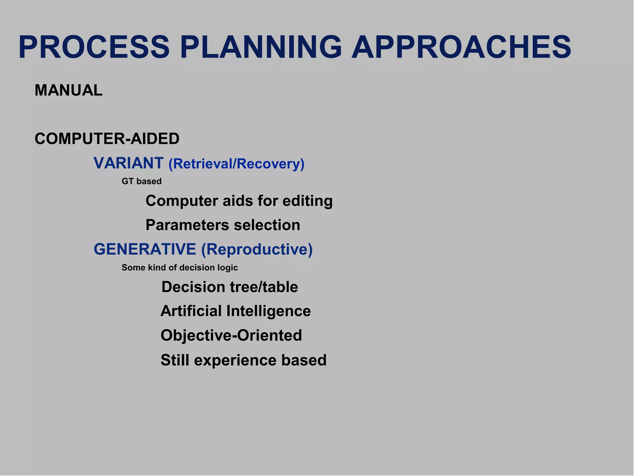
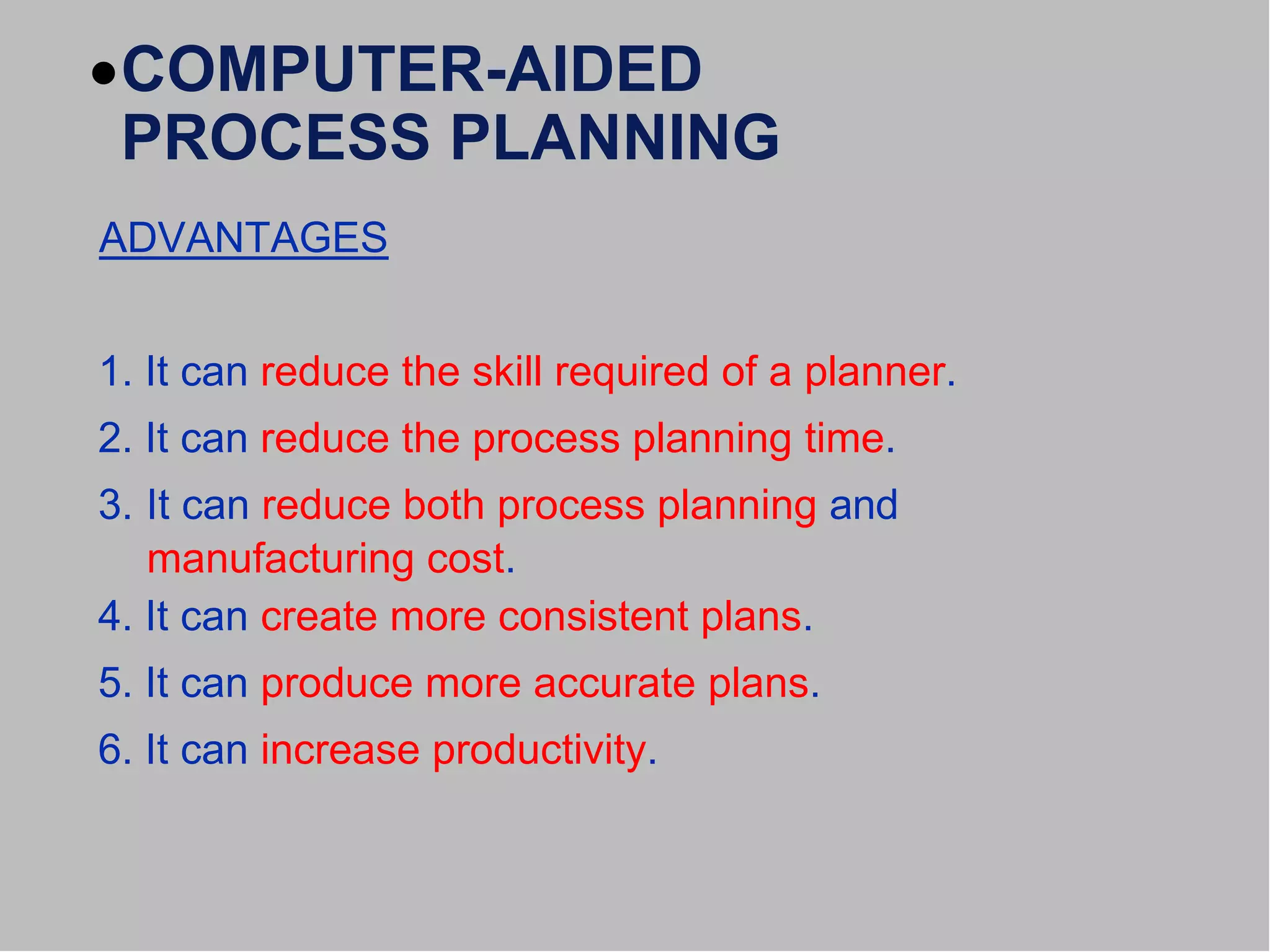
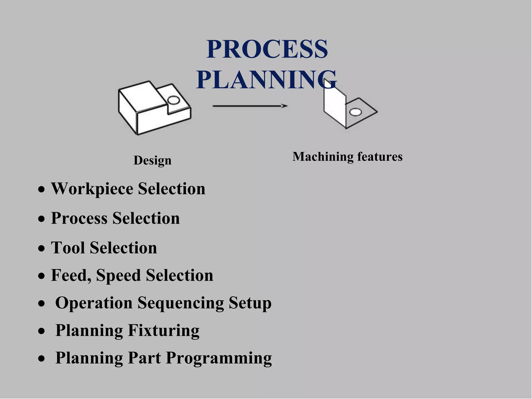
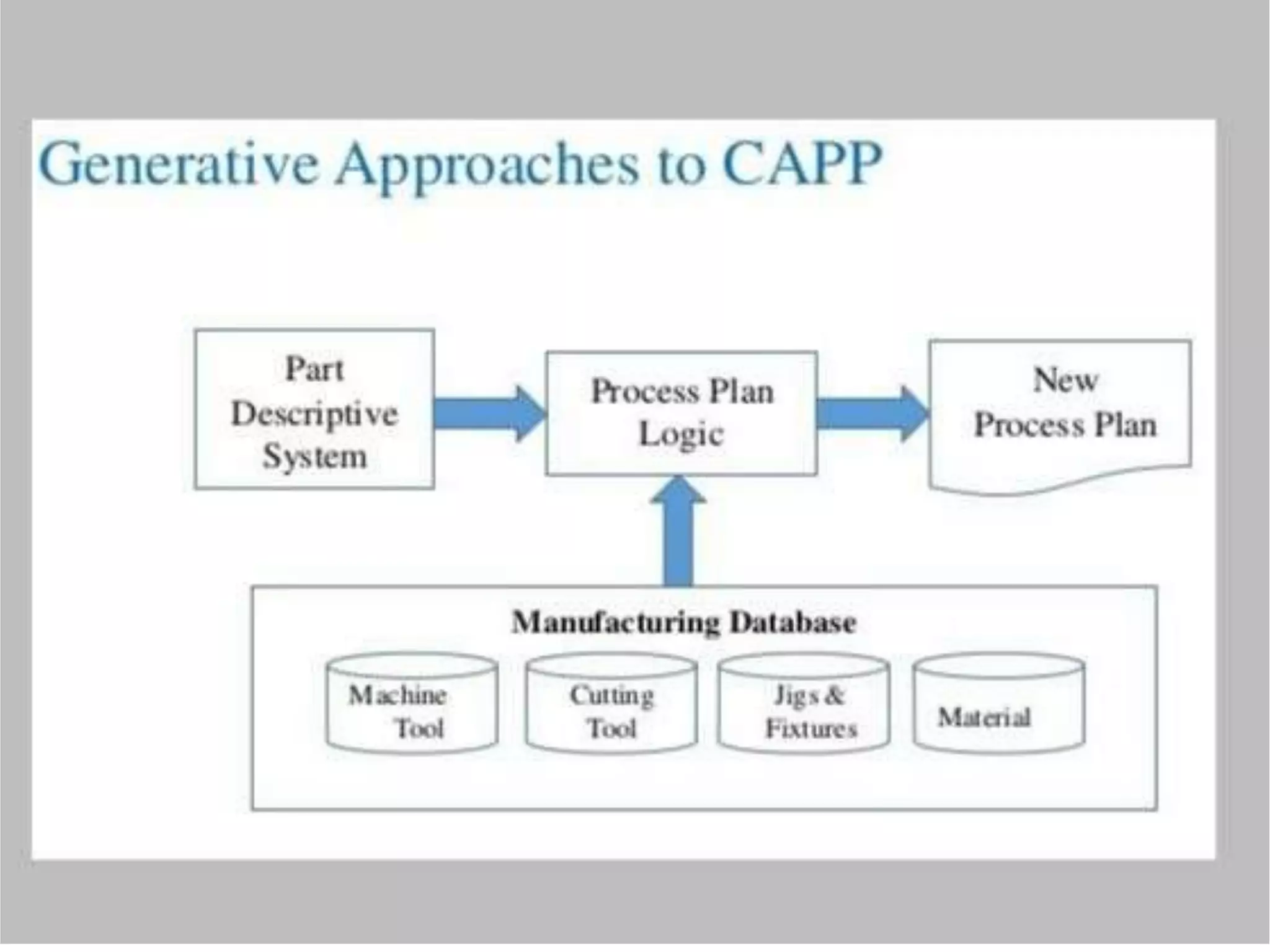
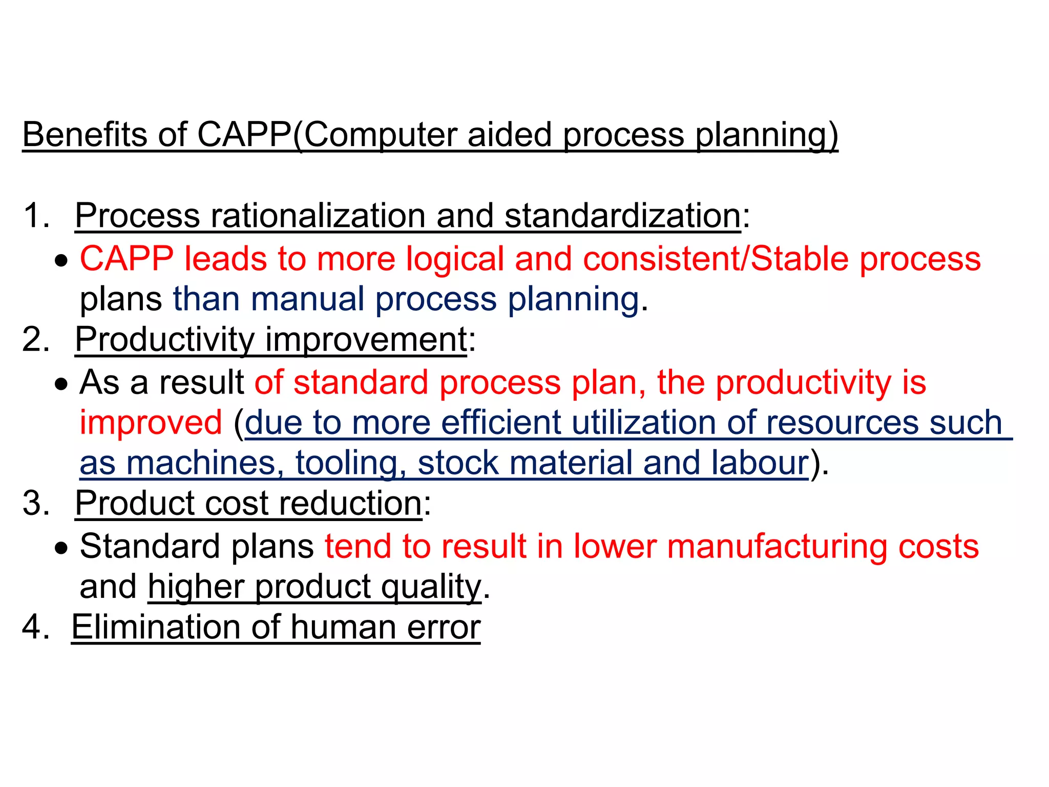
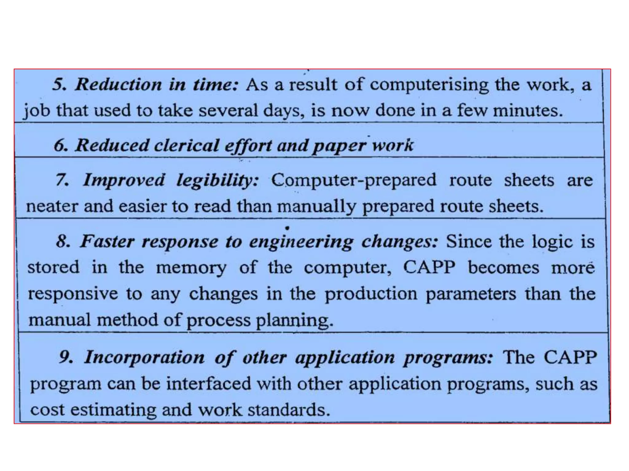
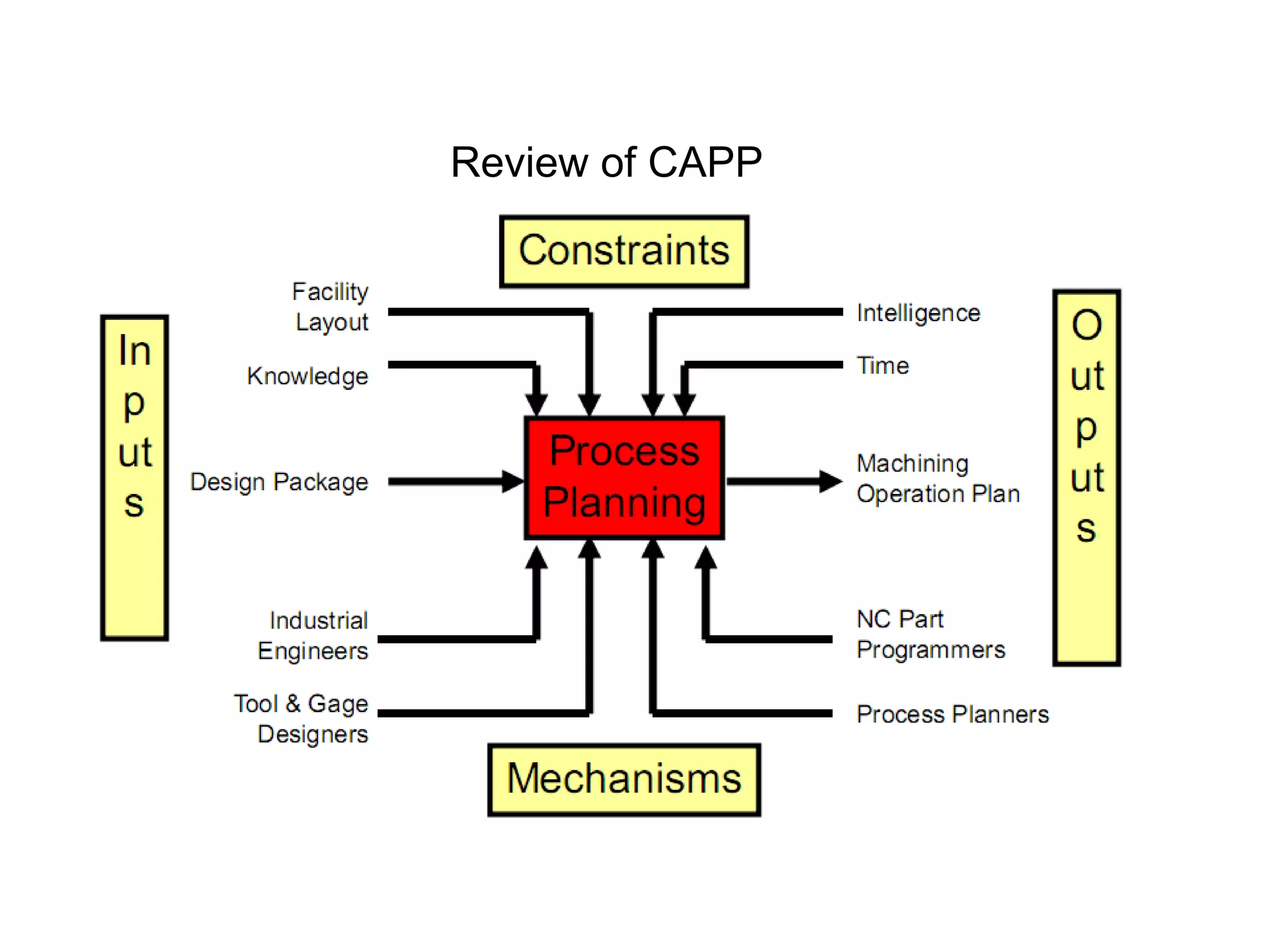
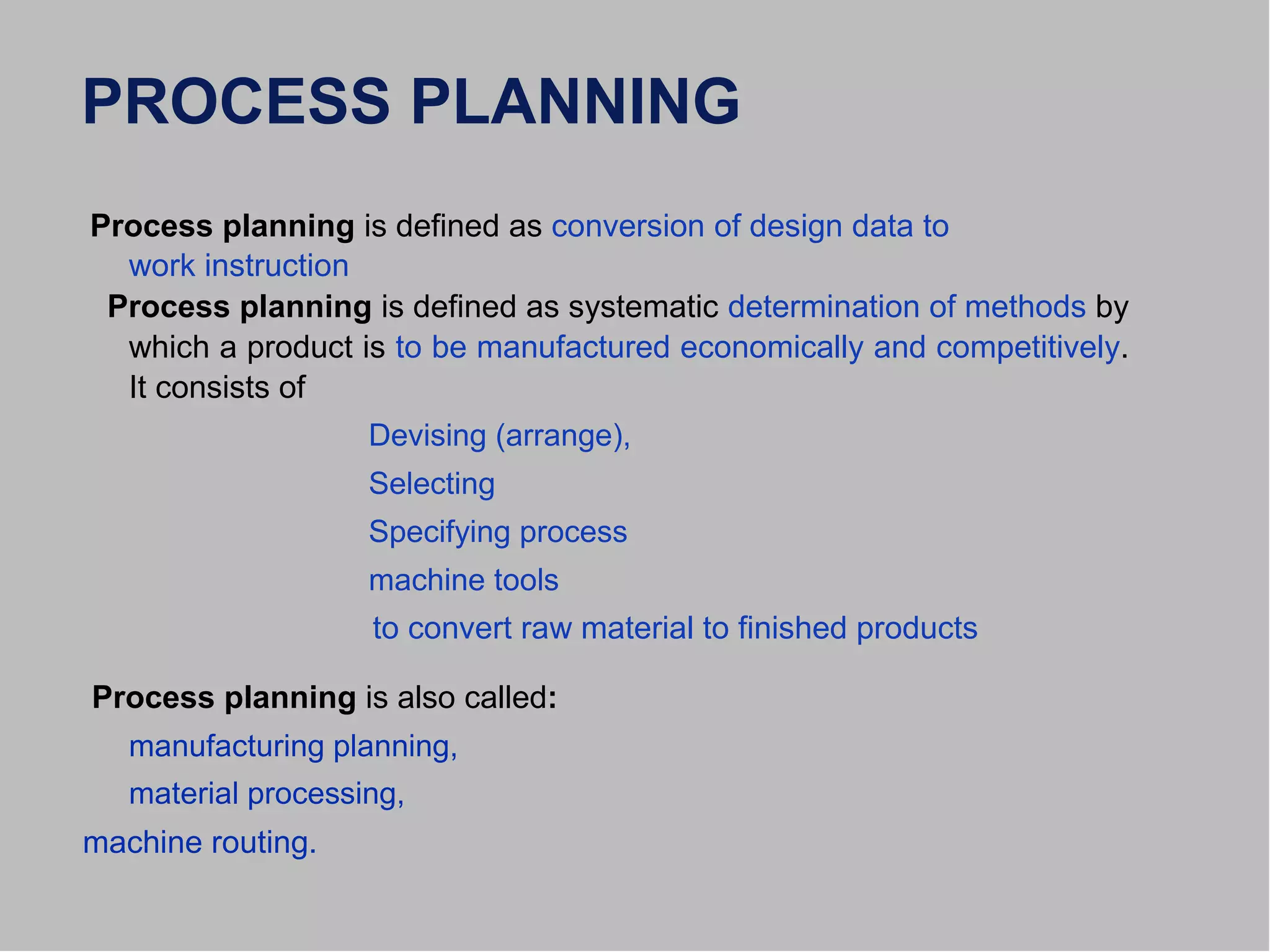
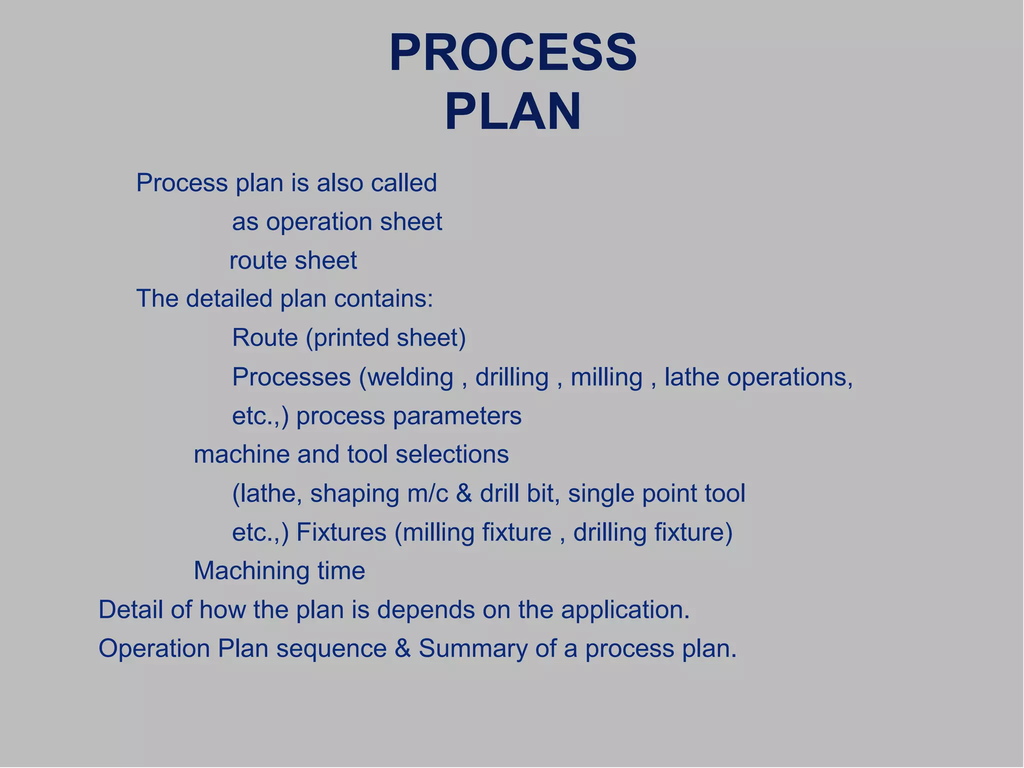
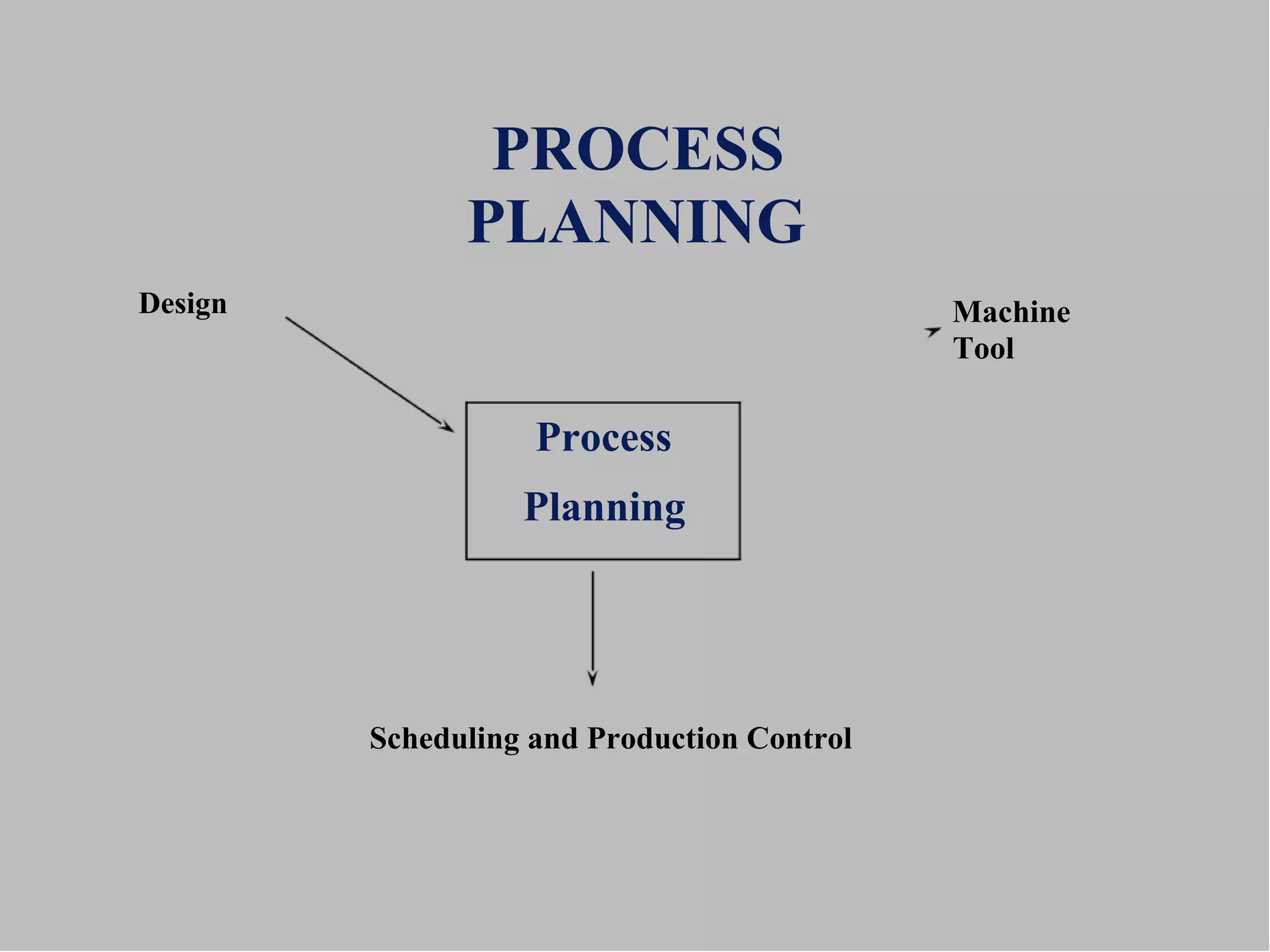
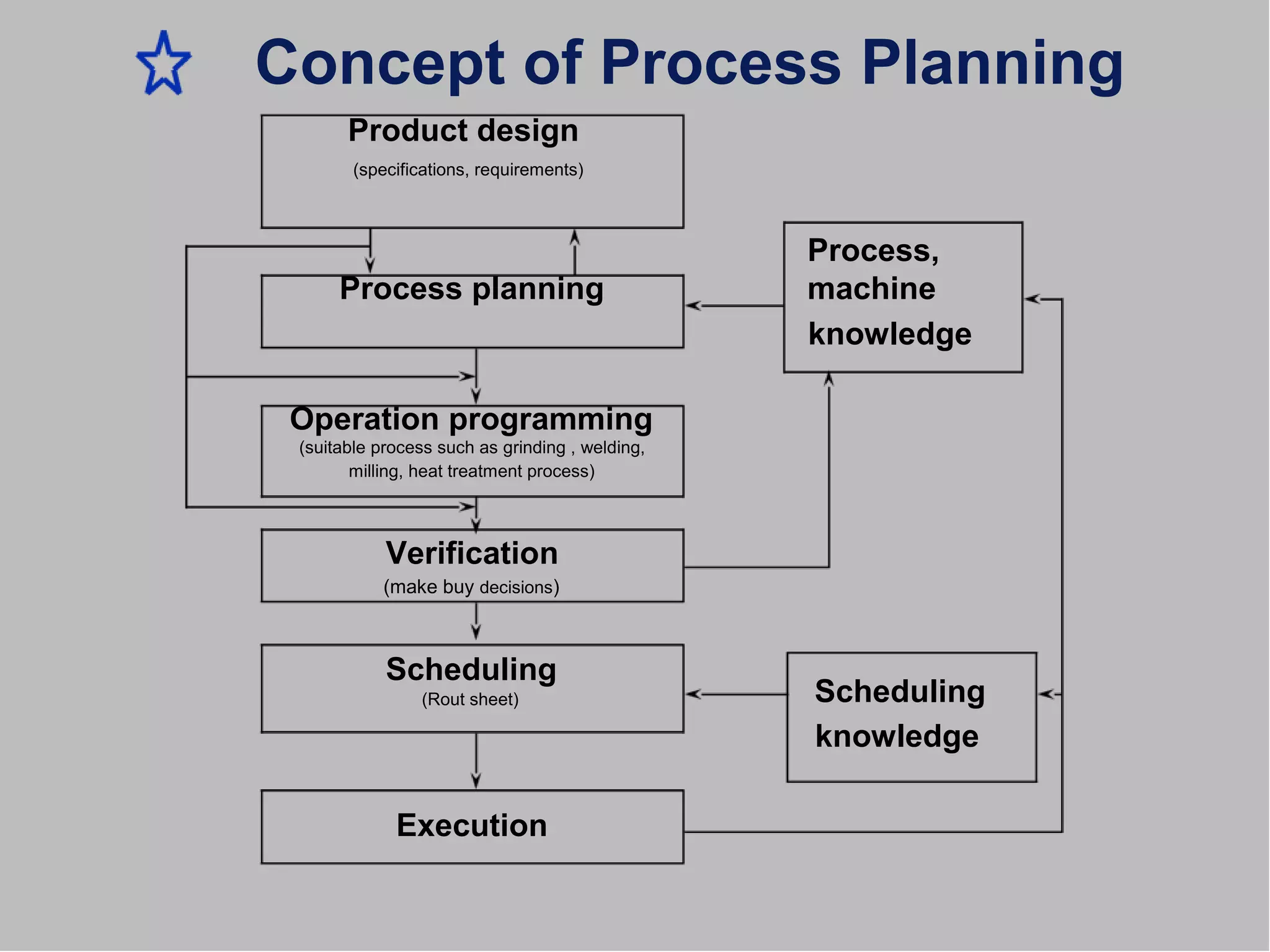
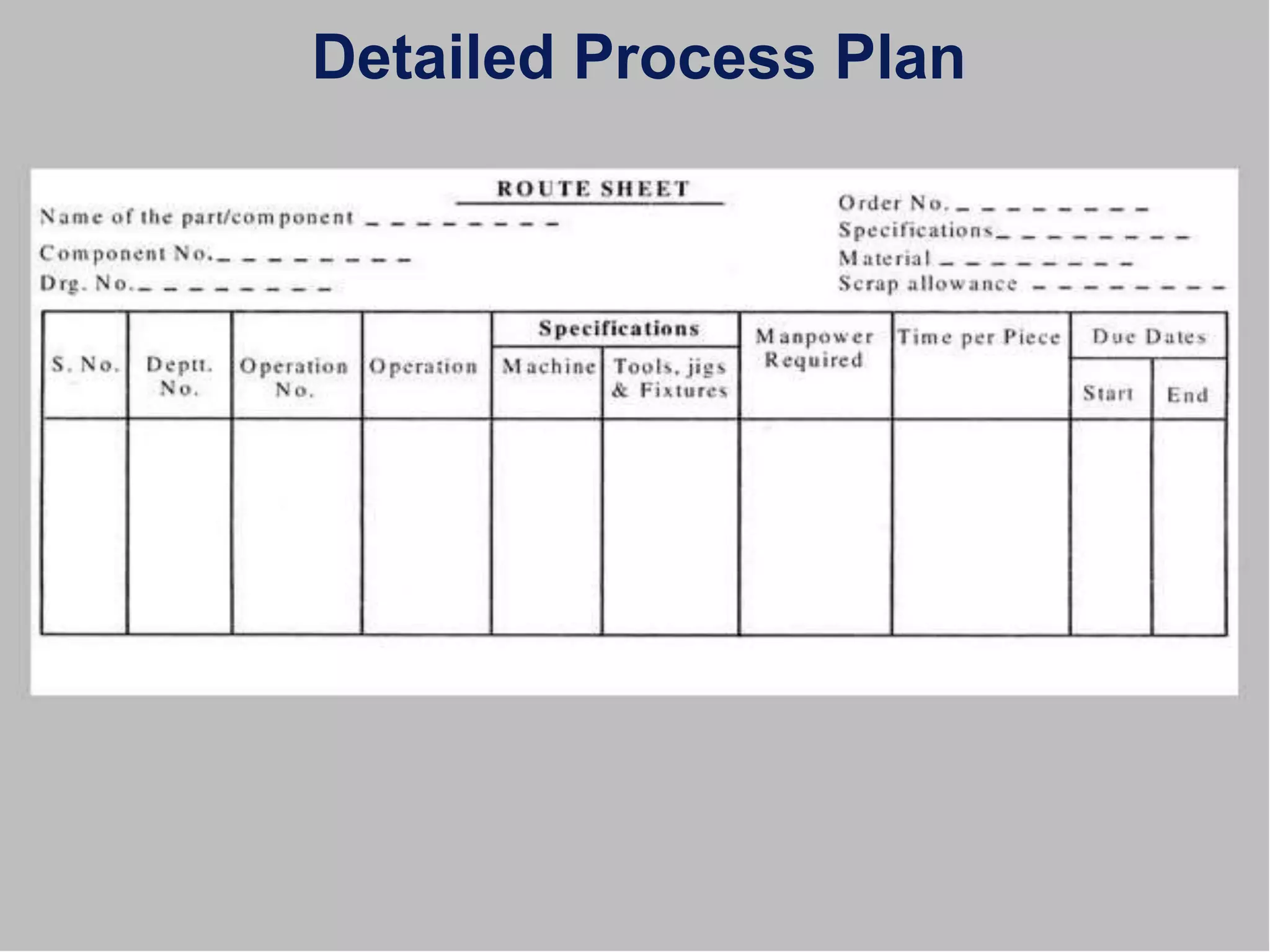
High Profile Call Girls Nagpur Isha Call 7001035870 Meet With Nagpur Escorts
1-unit(Introduction to process planning)-converted.docx
1. PROCESS PLANNING
Process planning is defined as conversion of design data to
work instruction
Process planning is defined as systematic determination of methods by
which a product is to be manufactured economically and competitively.
It consists of
Devising (arrange),
Selecting
Specifying process
machine tools
to convert raw material to finished products
Process planning is also called:
manufacturing planning,
material processing,
machine routing.
2. PROCESS
PLAN
Process plan is also called
as operation sheet
route sheet
The detailed plan contains:
Route (printed sheet)
Processes (welding , drilling , milling , lathe operations,
etc.,) process parameters
machine and tool selections
(lathe, shaping m/c & drill bit, single point tool
etc.,) Fixtures (milling fixture , drilling fixture)
Machining time
Detail of how the plan is depends on the application.
Operation Plan sequence & Summary of a process plan.
6. Process Planning Activities
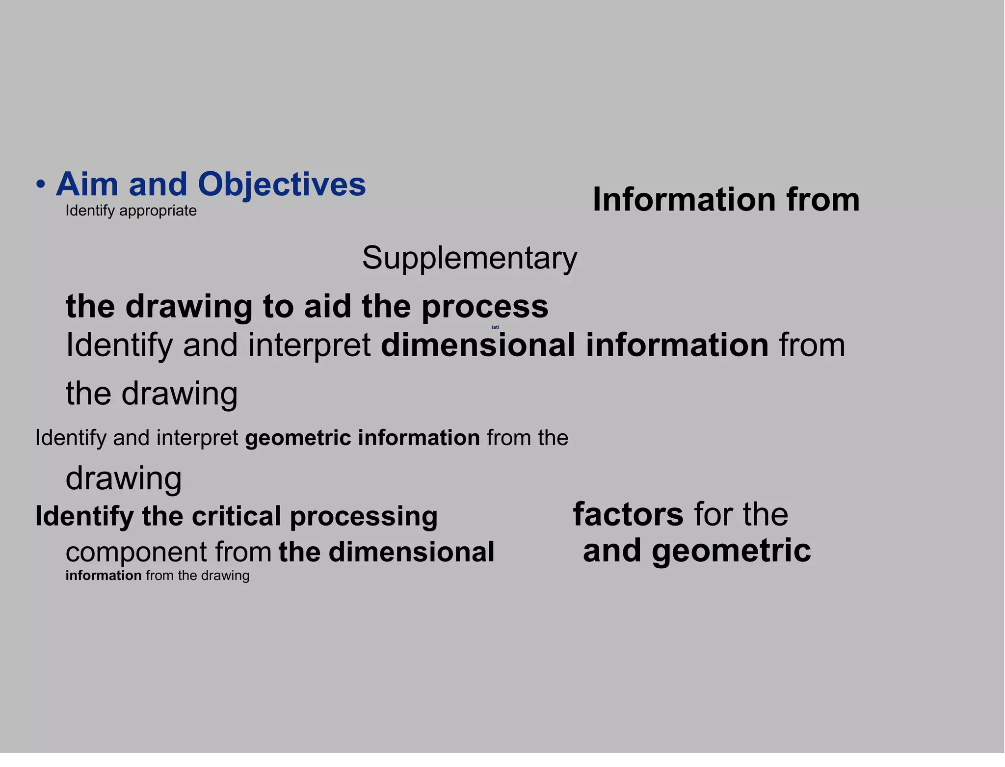
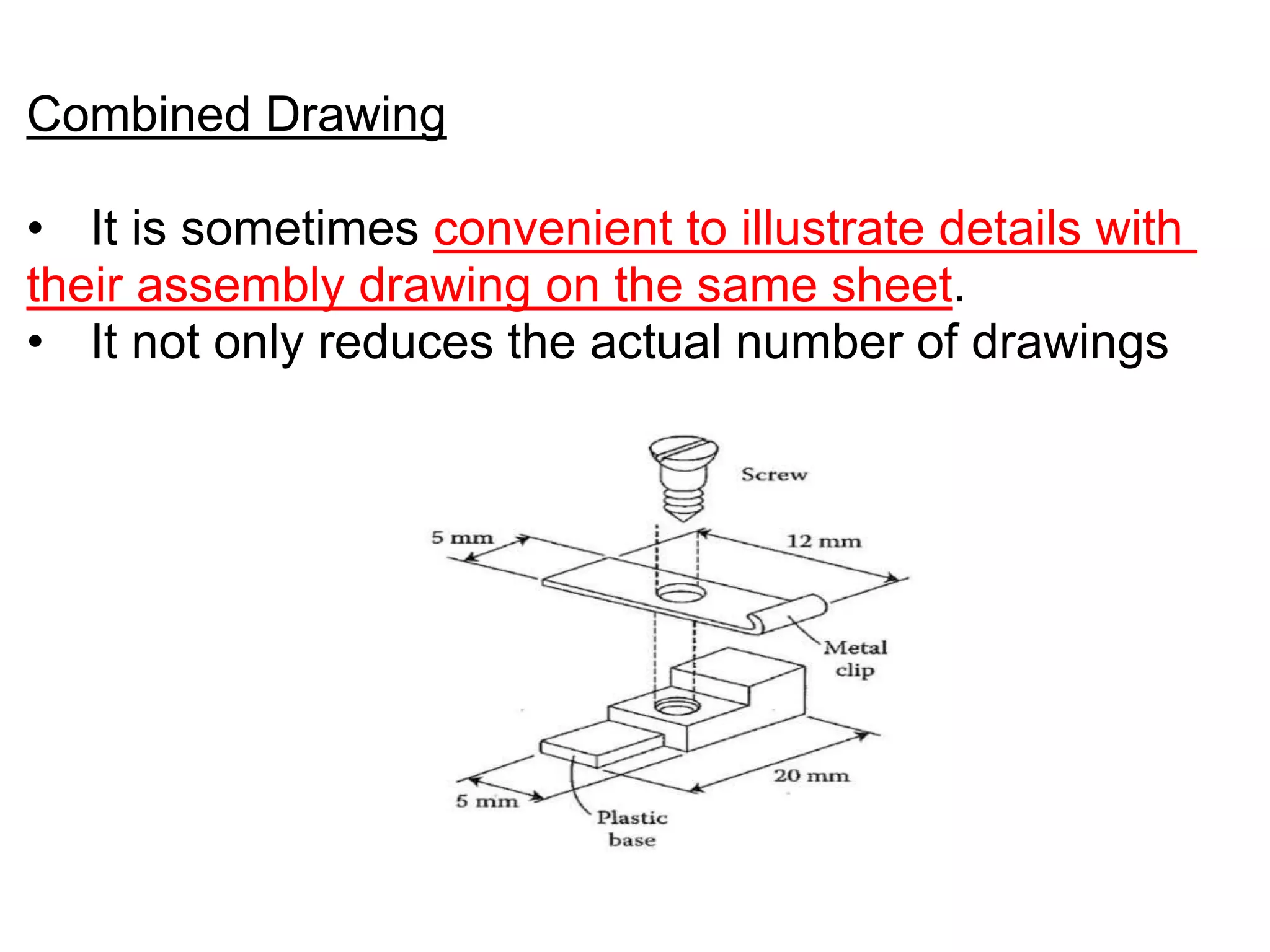
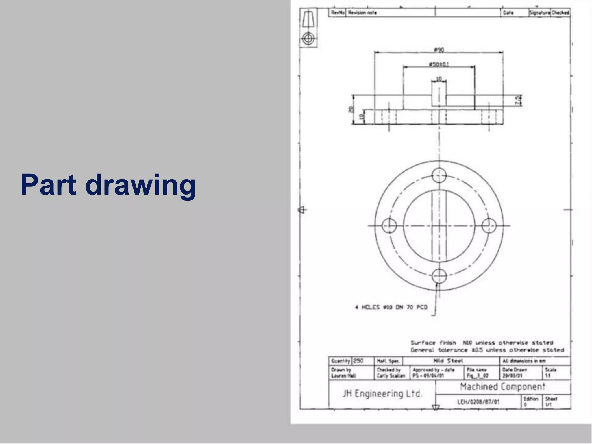
Analyse (Part ,dimension requirements) [DRAWING INTERPRETATION]
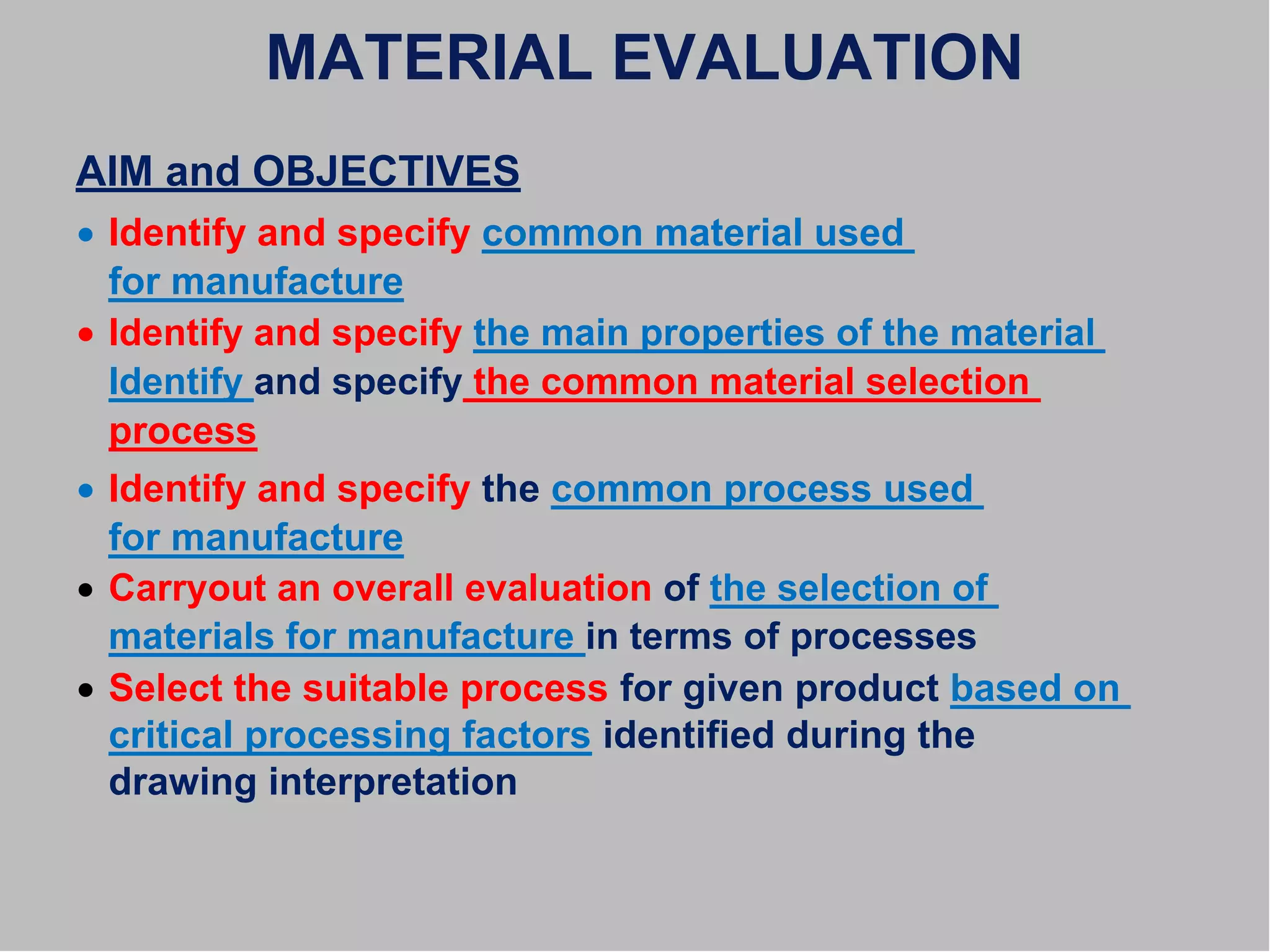
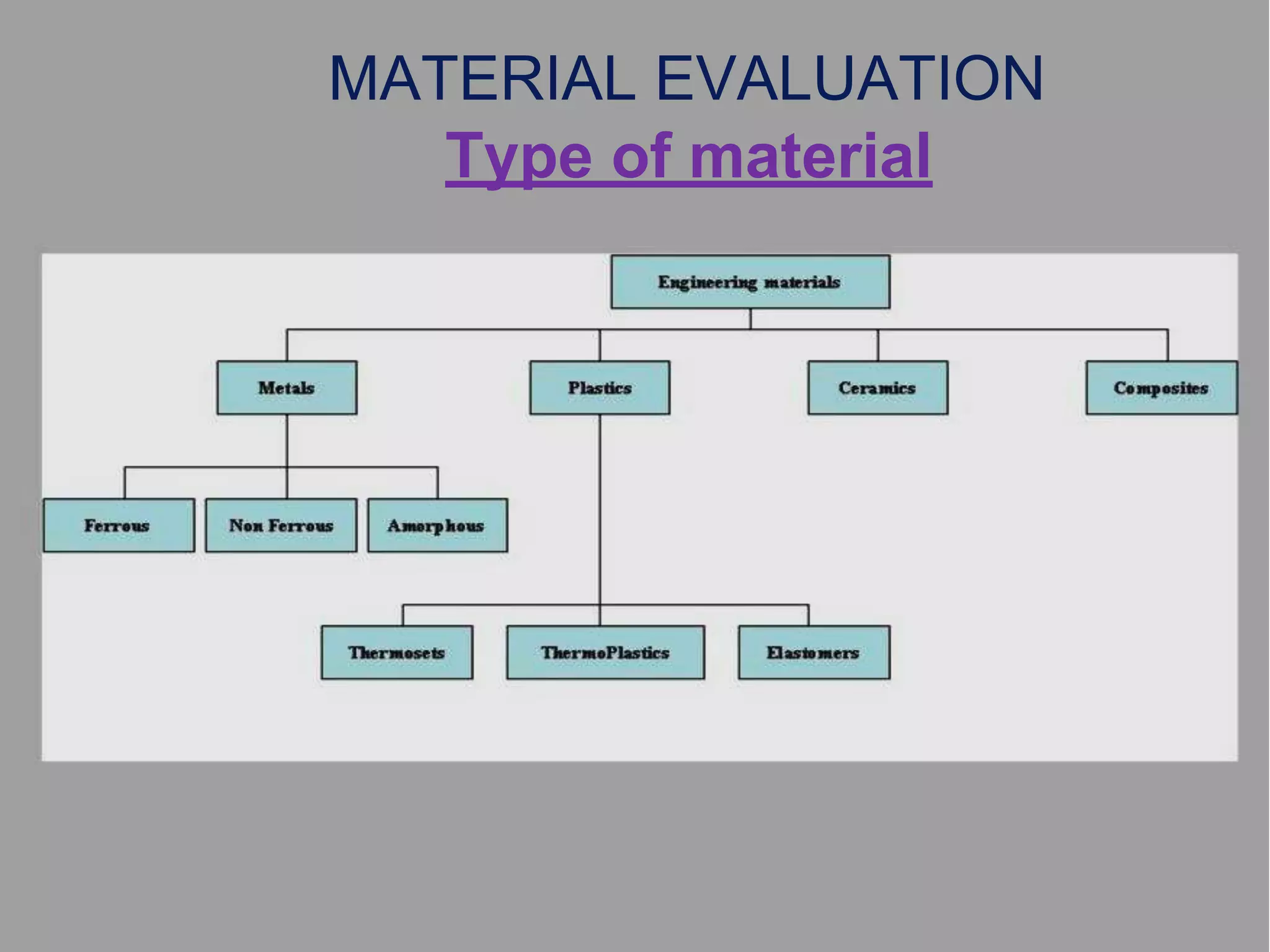
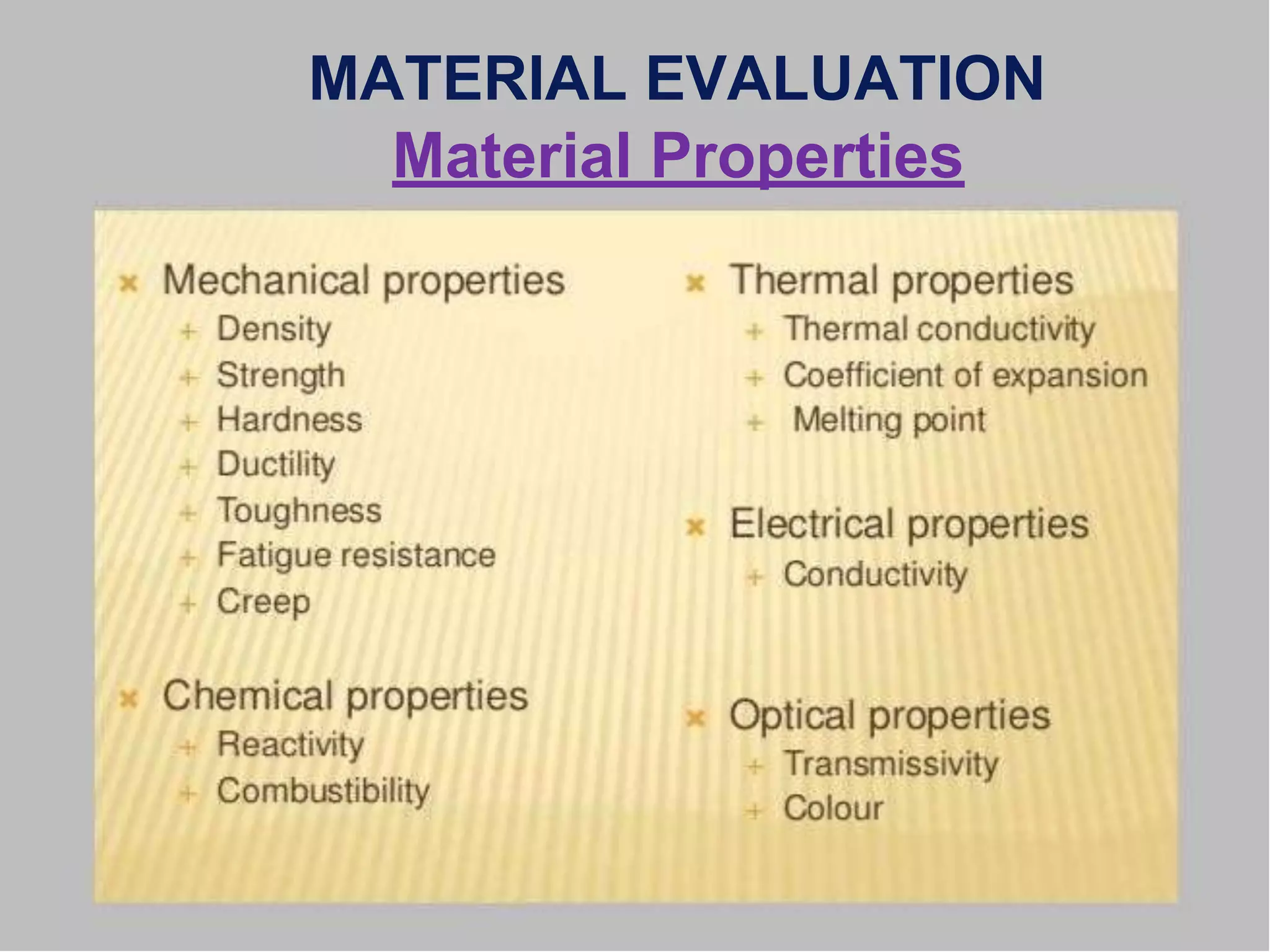
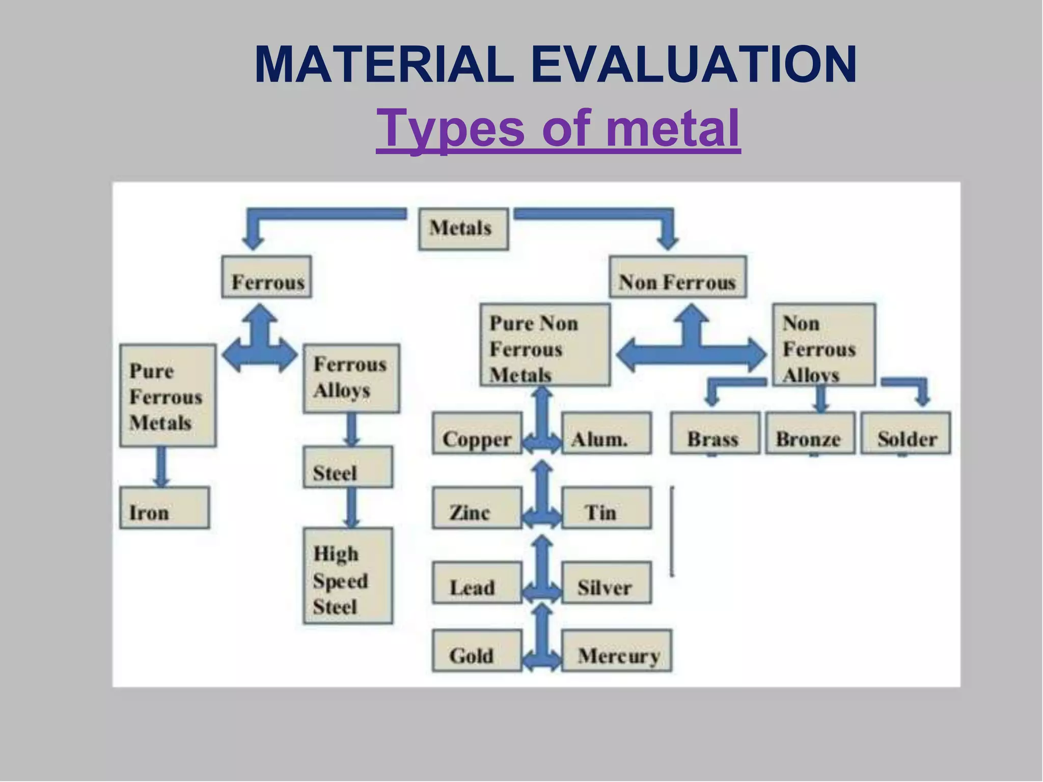
Determine (operation sequence) [MATERIAL EVALUATION AND PROCESS SELECTION]
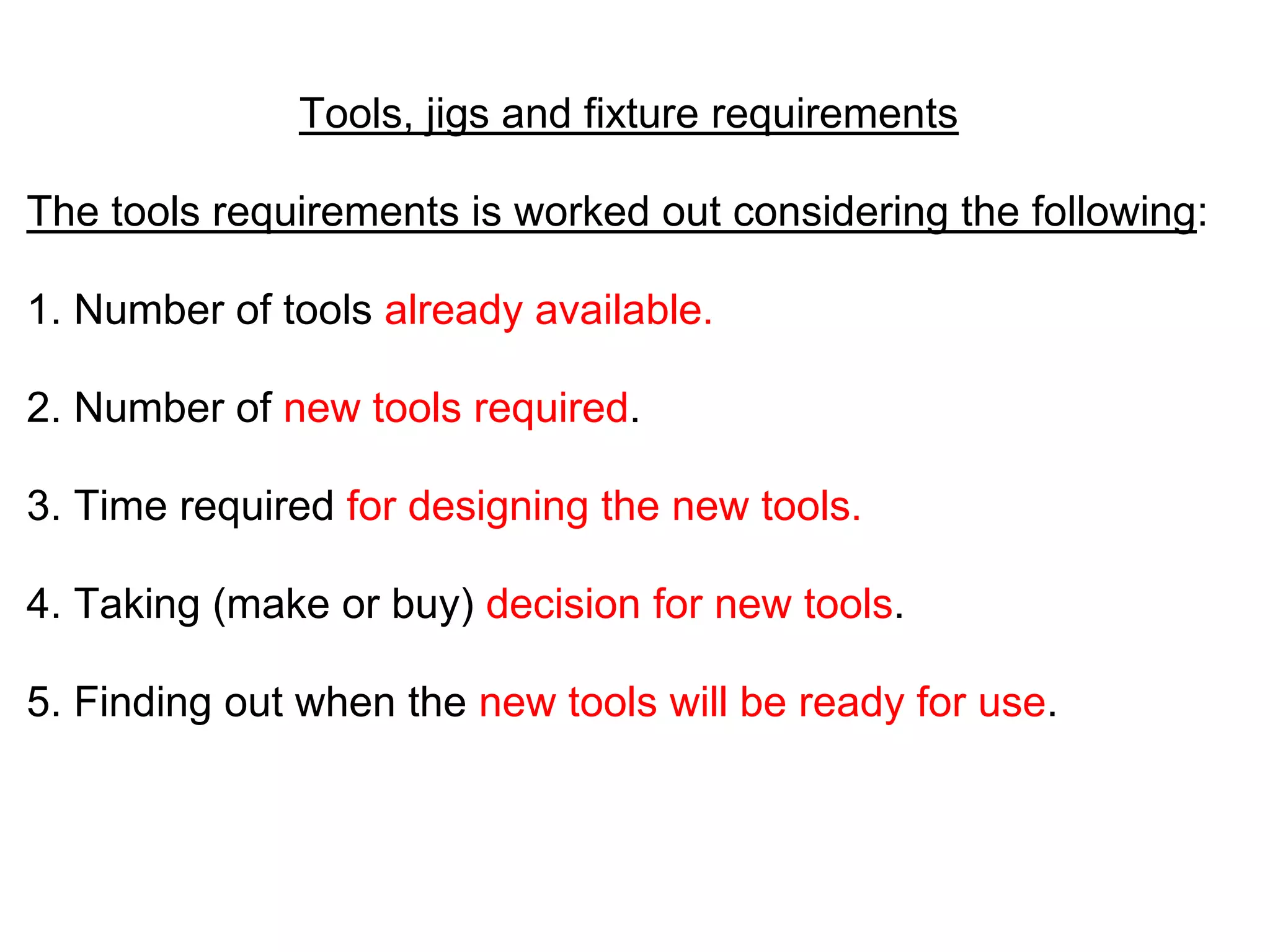
Select (equipment ) [SELECTION OF MACHINES . TOOLING and WORK HOLDING DEVICE]
Calculate (processing times ) [SETTING PROCESS PARAMETERS]
Select (QA/Inspection methods) [SELECTING QUALITY ASSURANCE METHOD]
Estimate (manufacturing cost) [COST ESTIMATING]
Document (Process Plan ) [PREPARING PROCESS PLANNING DOCUMENTATION]
Communicate (manufacturing Engineer with shop floor)
7. • Aim and Objectives
Identify appropriate
Supplementary
the drawing to aid the process
Identify and interpret dimensional information from
the drawing
Identify and interpret geometric information from the
drawing
Identify the critical processing factors for the
component from the dimensional and geometric
information from the drawing
tati
Information from
8. • Types of Drawing
Detail drawing
I. Single part drawing
II. Collective drawing
Assembly drawing
I. Single assembly drawing
II. Collective assembly drawing
Combined drawing
10. Single-part drawings are workshop drawings that
show the fabrication information for one part
(usually without welds).
Single-part drawings usually use small sheet sizes.
11. Collective Drawings:
• A similar parts or assembly are collected together in
one common document.
Each item or assembly will be given with drawing
number or code number for identification.
12.
13. Assembly drawings can be used to represent items
that consist of more than one component.
Assembly drawings may include instructions, lists
of the component parts, reference numbers, and
references to detail drawings or shop drawings, and
specification information.
15. Combined Drawing
• It is sometimes convenient to illustrate details with
their assembly drawing on the same sheet.
• It not only reduces the actual number of drawings
17. • Shape
FACTORS AFFECTING
PROCESS
PLAN SELECTION
• Tolerance
• Surface finish
• Size
• Material type
• Quantity
• Value of the product
• Urgency
• Manufacturing system itself
• etc.
18. MATERIAL EVALUATION
• IMPORTANT FACTORS
Product design must meet the specified need
Materials with appropriate properties must be
selected
Suitable manufacturing process must be
selected the response of the material during
manufacture and its service
19. MATERIAL EVALUATION
AIM and OBJECTIVES
Identify and specify common material used
for manufacture
Identify and specify the main properties of the material
Identify and specify the common material selection
process
Identify and specify the common process used
for manufacture
Carryout an overall evaluation of the selection of
materials for manufacture in terms of processes
Select the suitable process for given product based on
critical processing factors identified during the
drawing interpretation
23. PROCESS PLANNING APPROACHES
MANUAL
COMPUTER-AIDED
VARIANT (Retrieval/Recovery)
GT based
Computer aids for editing
Parameters selection
GENERATIVE (Reproductive)
Some kind of decision logic
Decision tree/table
Artificial Intelligence
Objective-Oriented
Still experience based
24. REQUIREMENTS IN MANUAL
PROCESS PLANNING
Ability to interpret an engineering drawing.
• Familiar with manufacturing processes and practice.
• Familiar with tooling and fixtures.
• Know what resources are available in the shop.
• Know how to use reference books, such
as machinability data handbook.
• Able to do computations on machining time and cost.
• Familiar with the raw materials.
• Know the relative costs of processes, tooling,
and raw materials.
25. MANUAL PROCESS PLANNING STEPS
• Study the overall shape of the part.
• Use this information to classify the part and determine the
type of workstation needed.
• Thoroughly study the drawing. Try to identify every
manufacturing features and notes.
• If raw stock is not given, determine the best raw material
shape to use.
• Identify datum surfaces. Use information on datum
surfaces to determine the setups.
• Select machines for each setup.
• For each setup determine the rough sequence of
operations necessary to create all the features.
26. MANUAL PROCESS PLANNING STEPS
• Sequence the operations determined in the
previous step.
• Select tools for each operation.
• Try to use the same tool for several operations if it is
possible.
• Keep in mind the trade off on tool change time and
estimated machining time.
• Select or design fixtures for each setup.
• Evaluate the plan generate thus far and make
necessary modifications.
• Select cutting parameters for each operation.
• Prepare the final process plan document.
27. COMPUTER-AIDED
PROCESS PLANNING
ADVANTAGES
1. It can reduce the skill required of a planner.
2. It can reduce the process planning time.
3. It can reduce both process planning and
manufacturing cost.
4. It can create more consistent plans.
5. It can produce more accurate plans.
6. It can increase productivity.
29. PROCESS
PLANNING
Design Machining features
Workpiece Selection
Process Selection
Tool Selection
Feed, Speed Selection
Operation Sequencing Setup
Planning Fixturing
Planning Part Programming
30. PROBLEMS ASSOCIATED WITH
THE VARIANT APPROACH
1. The components to be planned are limited to similar
components previously planned.
2. Experienced process planners are still required to
modify the standard plan for the specific component.
3. Details of the plan cannot be generated.
4. Variant planning cannot be used in an entirely
automated manufacturing system, without additional
process planning.
31. ADVANTAGES OF THE
VARIANT APPROACH
1. Once a standard plan has been written, a variety
of components can be planned.
2. Comparatively simple programming and installation
(compared with generative systems) is required to
implement a planning system.
3. The system is understandable, and the planner has
control of the final plan.
4. It is easy to learn, and easy to use.
32. GENERATIVE APPROACH
A system which automatically synthesizes a process
Plan for a new component.
MAJOR COMPONENTS:
(i) part description
(ii) manufacturing databases
(iii) decision making logic and algorithms
33. ADVANTAGES OF THE
GENERATIVE APPROACH
1. Generate consistent process plans rapidly;
2. New components can be planned as easily
as existing components;
3. It has potential for integrating with an
automated manufacturing facility to provide
detailed control information.
34.
35.
36.
37.
38.
39. Benefits of CAPP(Computer aided process planning)
1. Process rationalization and standardization:
CAPP leads to more logical and consistent/Stable process
plans than manual process planning.
2. Productivity improvement:
As a result of standard process plan, the productivity is
improved (due to more efficient utilization of resources such
as machines, tooling, stock material and labour).
3. Product cost reduction:
Standard plans tend to result in lower manufacturing costs
and higher product quality.
4. Elimination of human error
40.
41. General steps involved in CAPP
Design input, Material selection,Process selection
Process sequencing, Machine and tool selection
Intermediate surface determination, Fixture selection
Machining parameter selection,Cost/time estimation
Plan preparation, Mc tape image generation
These are the general steps involved in the computer aided
process planning
42. Dis Advantages
While compared with manual process planning the CAPP
systems have few dis Advantages:
The inability to show special manufacturing techniques.
The initial cost of establishing a CAPP system
Is high while compared with manual process planning.
44. MATERIAL EVALUATION
Selection of material has become complicated by the great
increase not only in the kinds of materials but also in the
various forms in which any one material may be available.
Material should be of right quality and chemical composition
as per the product specifications.
Shape and size of material should restrict the scrap (i.e.,
material removed for getting the product shape).
45. Bill of Material
Bill of material is a means of determining, purchasing and
production order requirements.
It should indicate if the part is to be manufactured or
purchased.
The production control department uses the bill of material to
determine manufacturing and scheduling dates.
Process engineering uses it as a checklist to complete their
work
46. The information usually required on the bill of material
1. The product name.
2. Product code identification.
3. Sheet number.
4. Use.
5. Date of preparation.
6. Name/initials of preparer.
7. Name/initials of checker.
8. Item numbers.
9. Make/purchase designations.
10. Subassembly part numbers and names.
11. Quantity requirements, and
12. Material used in each part.
47.
48. Selection of “jigs, fixtures and other special attachments”
These supporting devices are necessary
• To give higher production rate.
• To reduce cost of production per piece.
Selection of “cutting tools and inspection gauges”
They, respectively, are necessary to
• Reduce production time.
• Inspect accurately and at a faster rate.
49. Tools, jigs and fixture requirements
The tools requirements is worked out considering the following:
1. Number of tools already available.
2. Number of new tools required.
3. Time required for designing the new tools.
4. Taking (make or buy) decision for new tools.
5. Finding out when the new tools will be ready for use.