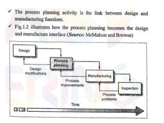
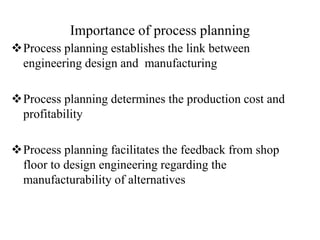
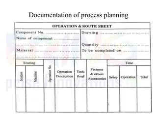
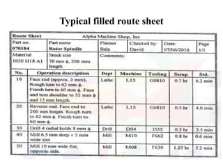
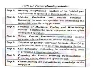
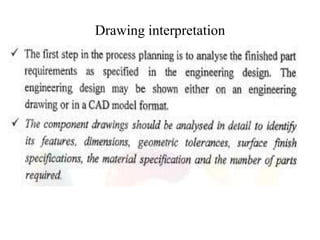
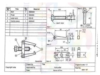
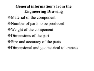
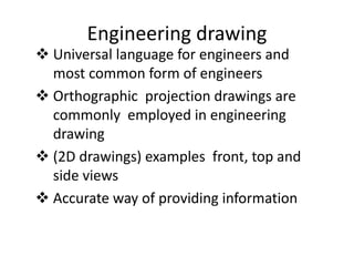
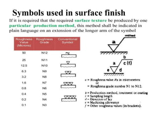
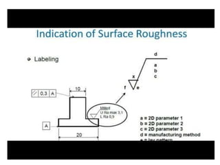
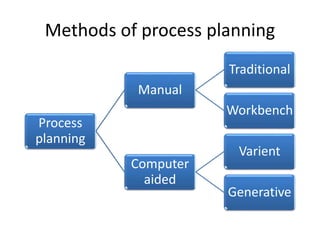
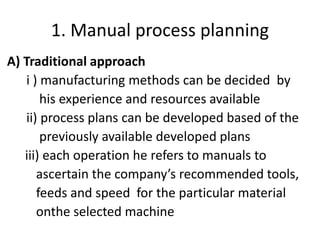
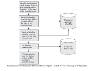
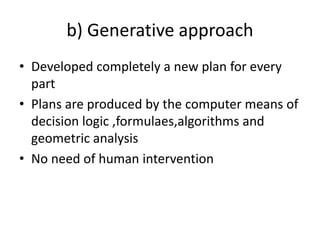
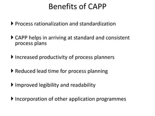
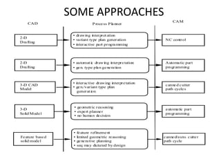
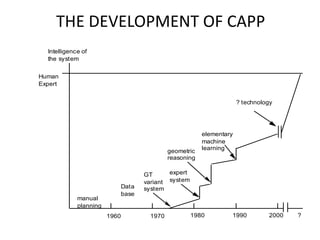
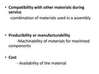
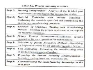
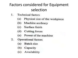
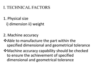
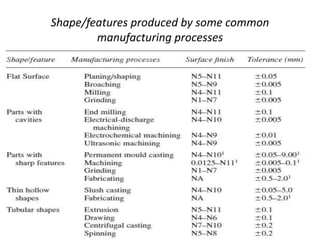
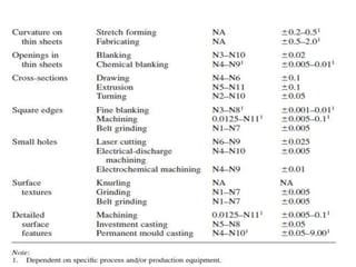
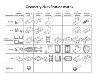
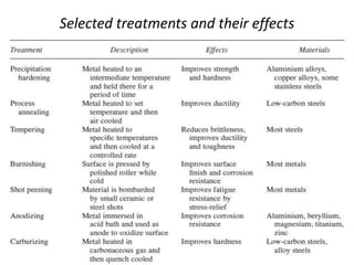
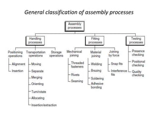
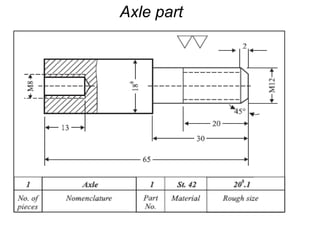
SlideShare a Scribd company logo
1 of 76
Process Planning and Cost
Estimation
Unit 1 - Introduction to Process Planning
Process planning
 Process planning consists of preparing set of
instructions that describe how to manufacture the
product and its design
 Process planning is the detailed specifications that list
the operations, tools and facilities
 According to American society of tool and
manufacturing engineers “ it is the systematic
determination of the methods by which a product is to
be manufactured competitively and economically ’’
Importance of process planning
Process planning establishes the link between
engineering design and manufacturing
Process planning determines the production cost and
profitability
Process planning facilitates the feedback from shop
floor to design engineering regarding the
manufacturability of alternatives
Documentation of process planning
Typical filled route sheet
Drawing interpretation
General information's from the
Engineering Drawing
Material of the component
Number of parts to be produced
Weight of the component
Dimensions of the part
Size and accuracy of the parts
Dimensional and geometrical tolerances
Engineering drawing
 Universal language for engineers and
most common form of engineers
 Orthographic projection drawings are
commonly employed in engineering
drawing
 (2D drawings) examples front, top and
side views
 Accurate way of providing information
Types of drawing
1.Detailed drawings
2. ASSEMBLY DRAWINGS –
a) collective assembly drawing
b) COMBINED DETAILED ASSEMBLY DRAWING
Important parameters considered
for process planners
Dimensions
Material specifications
Material treatment
Tolerances, limits and fits
Surface finish
1. Tolerances
a) Dimensional tolerances
If the dimension is specified in ‘mm’as 10±0.02, then
the part will be acceptable if the dimension is manufactured
to an actual size between 9.98 and 10.02mm
General tolerances
General tolerance notes apply to all unspecified
dimensions on a drawing
B. Geometrical tolerance
 Permissible variation of form and location of a feature of
the component
TYPES OF GEOMETRICAL TOLERANCING
GENERAL REPRESENTATION OF
TOLERANCE DRAWING
Example of Engineering drawing
RUN OUT
CONCENTRICITY
ANGULARITY PROFILE OF A
SURFACE
C. Limits and fits
1. Hole basis system
Size of the hole is kept constant , shaft size is
varied to get different fits
2. Shaft basis system
size of the shaft is kept constant , hole size
varies
Fit
Fit represents the tightness or looseness between two
mating parts. Between the shaft and hole
1. Clearance fit
2. Transition fit
3. Interference fit
SURFACE FINISH
Surface finish is the depth of irregularities of a surface
resulting from the manufacturing process used to
produce it
Basic types of surface irregularities
a) form error
b) roughness
c) waviness
a) Form error
- for longer wavelength deviation
- results from large scale problems in the manufacturing
process
- Errors in machine tool ways , guides or spindles and
inaccurate alignment of work piece
b) Roughness
- finest irregularities of a surface (longest wavelength)
- results from a particular production process or material
condition
c) waviness
-more widely spaced longer deviations of a surface
from its nominal surface
- waviness generally caused by the vibration or heat
Symbols used in surface finish
Methods of process planning
Process
planning
Manual
Traditional
Workbench
Computer
aided
Varient
Generative
1. Manual process planning
A) Traditional approach
i ) manufacturing methods can be decided by
his experience and resources available
ii) process plans can be developed based of the
previously available developed plans
iii) each operation he refers to manuals to
ascertain the company’s recommended tools,
feeds and speed for the particular material
onthe selected machine
B) Work book approach
 It involves developing workbooks of
predetermined sequences of operation for
given types of work pieces
After carrying out the drawing interpretation
and identified the manufacturing process
required
The sequence of predetermined operations
can be selected from the work book
Advantages of manual process
palnning
Low cost
Flexible to change the process plans easily
Disadvantages
Excessive clerical work
Lack of consistency in planning
Late design modifications
2. Computer aided process
Planning (CAPP)
Process planning can be done with the help of
computers
To overcome the drawbacks of manual process
planning computer aided process planning(CAPP)
can be used
TYPES OF CAPP
Varient approach (Retrieval approach)
Generative approach
a) Varient approach
• It is similar to manual process approach as it
retrieves a standard plan an modifies to suit
for a given part
• The standard plans are grouped according to
group technology(GT) classification and coding
• The process plans for the part under
consideration is compiled by retrieving those
of standard plans that are relevent
b) Generative approach
• Developed completely a new plan for every
part
• Plans are produced by the computer means of
decision logic ,formulaes,algorithms and
geometric analysis
• No need of human intervention
Benefits of CAPP
 Process rationalization and standardization
 CAPP helps in arriving at standard and consistent
process plans
 Increased productivity of process planners
 Reduced lead time for process planning
 Improved legibility and readability
 Incorporation of other application programmes
SOME APPROACHES
CAD
CAM
2-D
Drafting
Process Planner
• automatic drawing interpretation
• gen. type plan generation
Automatic part
programming
3-D
Solid Model
canned/auto. cutter
path cycle
Feature based
solid model
automatic part
programming
• feature refinement
• limited geometric reasoning
• generative planning
• seq may dictated by design
2-D
Drafting
• drawing interpretation
• variant type plan generation
• interactive part programming
NC control
3-D CAD
Model
• interactive drawing interpretation
• gen./variant type plan
generation
canned cutter
path cycles
• geometric reasoning
• expert planner
• no human decision
THE DEVELOPMENT OF CAPP
1960 1970 1980 1990 2000
Intelligence of
the system
Human
Expert
?
manual
planning
Data
base
GT
variant
system
expert
system
geometric
reasoning
elementary
machine
learning
? technology
PROCESS SELECTION
Factors Influencing Process Selection
• Shape requirements(geometrical form)
Example: solid shape, hollow shape, flat shape,
flanged shape, concave shape, convex shape,
cylindrical shape, presence of any part features such as
groove, threaded shape, hole, chamfer,
• Size or dimensional requirements
Process capable of handling parts of small sizes and
some processes can handle large sized parts
economically and effectively
• Surface finish requirements
Example : reaming process can provide a better
surface finish in a hole when compared with
drilling process
• Tolerance requirements
Example: grinding process always gives close
tolerances when compared with turning process
• Production volume requirements
Example: no. of components required on a
weekly, monthly or annual basis
• Material requirements
Example : hardness, and strength characteristics of
the material
Process selection parameters
• Nature of part, including materials, tolerances,
desired surface finish and operation required.
• Method of fabrication including machining or
assembling of similar parts or components.
• Limitation of facilities including the plant and
equipment available.
• Possibility of likely product design changes to
facilitate manufacturability or cost reduction.
• In-plant and outside materials handling
systems
• Inherent process to produce specified shape,
surface, finish to give desired mechanical
properties
• Available skill level of operators for the
production
Material Selection parameters
• Functional requirements
i) fatigue characteristics,
ii) strength,
iii) Hardness,
iv) Electrical and thermal properties.
• Reliability
- consistency with which the material will meet all
the products requirement throughout its service
life
• Service life durability
Years or hours of operation of the product to
perform its function satisfactorily
• Environmental Factors
Temperature, humidity, corrosive
• Aesthetics and appearance
i) colour, texture,
ii) lusture, smoothness and finish
• Compatibility with other materials during
service
-combination of materials used in a assembly
• Producibility or manufacturability
-Machinability of materials for machined
components
• Cost
- Availability of the material
Equipment and Tooling selection
Factors considered for Equipment
selection
I. TECHNICAL FACTORS
1. Physical size
i) dimension ii) weight
2. Machine accuracy
Able to manufacture the part within the
specified dimensional and geometrical tolerance
Machine accuracy capability should be checked
to ensure the achievement of specified
dimensional and geometrical tolerance
3. Surface finish
To ensure the achievement of specified
surface finish requirements of the component
in the design stage
4. Cutting forces
Machining parameters such as feed, speed
and depth of cut influence the various cutting
forces
Machine tool under consideration should be
provided the calculated cutting force for the
operation identified
5. Machine power
Power requirement of each operation is to be
identified to ensure the power rating of the
machine
Power required = cutting force X cutting speed
II. OPERATIONAL FACTORS
1. Batch size
2. Capacity
 Production rate of the machine
 Should be capable of achieving specified output per unit time
matching with master production schedule requirements
(MPS)
3. Availability
Refers to the proportion time of machine
availability to perform the work out of time
Availability affects the reliability, and overall
efficiency
Tooling selection
Factors in Tooling selection
Tooling selection method
Shape/features produced by some common
manufacturing processes
Geometry classification matrix
Selected treatments and their effects
General classification of assembly processes
Case study
Process planning of an axle part
Axle part
Set up sketch for each operation for manufacturing of Axle
UNIT 1 PPCE.ppt

More Related Content

Similar to UNIT 1 PPCE.ppt

unit-2-2110290540145.pptx, ppce unit 2 ppt
unit-2-2110290540145.pptx, ppce unit 2 pptunit-2-2110290540145.pptx, ppce unit 2 ppt
unit-2-2110290540145.pptx, ppce unit 2 pptRArivazhaganAssistan
 
Cim presentation (1)
Cim presentation (1)Cim presentation (1)
Cim presentation (1)rajnitj19
 
PROCESS PLANNING AND COST ESTIMATION
PROCESS PLANNING AND COST ESTIMATION PROCESS PLANNING AND COST ESTIMATION
PROCESS PLANNING AND COST ESTIMATION SIVASHANKAR N
 
TMA Module 2........................................................
TMA Module 2........................................................TMA Module 2........................................................
TMA Module 2........................................................4PS19AU411SyedaSoubi
 
Unit ii Process Planning
Unit ii Process PlanningUnit ii Process Planning
Unit ii Process PlanningAsha A
 
CADCAM CAE Notes
CADCAM CAE NotesCADCAM CAE Notes
CADCAM CAE NotesAbhay Gore
 
Experimental Studies on Effect of Layer Thickness on Surface Finish using FDM
Experimental Studies on Effect of Layer Thickness on Surface Finish using FDMExperimental Studies on Effect of Layer Thickness on Surface Finish using FDM
Experimental Studies on Effect of Layer Thickness on Surface Finish using FDMIRJET Journal
 
Process planning with an example
Process planning with an exampleProcess planning with an example
Process planning with an exampleHiran Gabriel
 
Group technology ppt @ bec doms
Group technology ppt @ bec domsGroup technology ppt @ bec doms
Group technology ppt @ bec domsBabasab Patil
 
Product and process planning
Product and process planningProduct and process planning
Product and process planningzimbar
 
OPTIMIZED MANUFACTURING PROCESSES FOR COOLER TANK
OPTIMIZED MANUFACTURING PROCESSES FOR COOLER TANKOPTIMIZED MANUFACTURING PROCESSES FOR COOLER TANK
OPTIMIZED MANUFACTURING PROCESSES FOR COOLER TANKIjripublishers Ijri
 
OPTIMIZED MANUFACTURING PROCESSES FOR COOLER TANK
OPTIMIZED MANUFACTURING PROCESSES FOR COOLER TANKOPTIMIZED MANUFACTURING PROCESSES FOR COOLER TANK
OPTIMIZED MANUFACTURING PROCESSES FOR COOLER TANKIjripublishers Ijri
 
Vibration control of newly designed Tool and Tool-Holder for internal treadi...
Vibration control of newly designed Tool and Tool-Holder for  internal treadi...Vibration control of newly designed Tool and Tool-Holder for  internal treadi...
Vibration control of newly designed Tool and Tool-Holder for internal treadi...IJMER
 
Process planning unit two
Process planning  unit twoProcess planning  unit two
Process planning unit twoZELALEMGIRMAW
 
B7 PROGRESSSSSS [Autosaved] (1).pptx
B7 PROGRESSSSSS [Autosaved] (1).pptxB7 PROGRESSSSSS [Autosaved] (1).pptx
B7 PROGRESSSSSS [Autosaved] (1).pptxZoicGaming
 
Computer Aided Design - Unit I Introduction
Computer Aided Design - Unit I IntroductionComputer Aided Design - Unit I Introduction
Computer Aided Design - Unit I IntroductionJayavendhanJ
 

Similar to UNIT 1 PPCE.ppt (20)

unit-2-2110290540145.pptx, ppce unit 2 ppt
unit-2-2110290540145.pptx, ppce unit 2 pptunit-2-2110290540145.pptx, ppce unit 2 ppt
unit-2-2110290540145.pptx, ppce unit 2 ppt
 
Cim presentation (1)
Cim presentation (1)Cim presentation (1)
Cim presentation (1)
 
PROCESS PLANNING AND COST ESTIMATION
PROCESS PLANNING AND COST ESTIMATION PROCESS PLANNING AND COST ESTIMATION
PROCESS PLANNING AND COST ESTIMATION
 
Unit 1
Unit   1Unit   1
Unit 1
 
Cad cam
Cad camCad cam
Cad cam
 
TMA Module 2........................................................
TMA Module 2........................................................TMA Module 2........................................................
TMA Module 2........................................................
 
Unit ii Process Planning
Unit ii Process PlanningUnit ii Process Planning
Unit ii Process Planning
 
CADCAM CAE Notes
CADCAM CAE NotesCADCAM CAE Notes
CADCAM CAE Notes
 
UNIT-1-PPCE.pptx
UNIT-1-PPCE.pptxUNIT-1-PPCE.pptx
UNIT-1-PPCE.pptx
 
K10672
K10672K10672
K10672
 
Experimental Studies on Effect of Layer Thickness on Surface Finish using FDM
Experimental Studies on Effect of Layer Thickness on Surface Finish using FDMExperimental Studies on Effect of Layer Thickness on Surface Finish using FDM
Experimental Studies on Effect of Layer Thickness on Surface Finish using FDM
 
Process planning with an example
Process planning with an exampleProcess planning with an example
Process planning with an example
 
Group technology ppt @ bec doms
Group technology ppt @ bec domsGroup technology ppt @ bec doms
Group technology ppt @ bec doms
 
Product and process planning
Product and process planningProduct and process planning
Product and process planning
 
OPTIMIZED MANUFACTURING PROCESSES FOR COOLER TANK
OPTIMIZED MANUFACTURING PROCESSES FOR COOLER TANKOPTIMIZED MANUFACTURING PROCESSES FOR COOLER TANK
OPTIMIZED MANUFACTURING PROCESSES FOR COOLER TANK
 
OPTIMIZED MANUFACTURING PROCESSES FOR COOLER TANK
OPTIMIZED MANUFACTURING PROCESSES FOR COOLER TANKOPTIMIZED MANUFACTURING PROCESSES FOR COOLER TANK
OPTIMIZED MANUFACTURING PROCESSES FOR COOLER TANK
 
Vibration control of newly designed Tool and Tool-Holder for internal treadi...
Vibration control of newly designed Tool and Tool-Holder for  internal treadi...Vibration control of newly designed Tool and Tool-Holder for  internal treadi...
Vibration control of newly designed Tool and Tool-Holder for internal treadi...
 
Process planning unit two
Process planning  unit twoProcess planning  unit two
Process planning unit two
 
B7 PROGRESSSSSS [Autosaved] (1).pptx
B7 PROGRESSSSSS [Autosaved] (1).pptxB7 PROGRESSSSSS [Autosaved] (1).pptx
B7 PROGRESSSSSS [Autosaved] (1).pptx
 
Computer Aided Design - Unit I Introduction
Computer Aided Design - Unit I IntroductionComputer Aided Design - Unit I Introduction
Computer Aided Design - Unit I Introduction
 

More from RArivazhaganAssistan

More from RArivazhaganAssistan (11)

fdffffffffgggjffhgjfjfjfhgjfhjhfjfhjhfdjhfdjhf
fdffffffffgggjffhgjfjfjfhgjfhjhfjfhjhfdjhfdjhffdffffffffgggjffhgjfjfjfhgjfhjhfjfhjhfdjhfdjhf
fdffffffffgggjffhgjfjfjfhgjfhjhfjfhjhfdjhfdjhf
 
metrology ansb vvhvghgvhgytfgggcvnbcvfcjhcajhchj
metrology ansb  vvhvghgvhgytfgggcvnbcvfcjhcajhchjmetrology ansb  vvhvghgvhgytfgggcvnbcvfcjhcajhchj
metrology ansb vvhvghgvhgytfgggcvnbcvfcjhcajhchj
 
UNIT 3 PPCE.pptx
UNIT 3 PPCE.pptxUNIT 3 PPCE.pptx
UNIT 3 PPCE.pptx
 
UNIT 2 PPCE.pptx
UNIT 2 PPCE.pptxUNIT 2 PPCE.pptx
UNIT 2 PPCE.pptx
 
ppt_mm.pptx
ppt_mm.pptxppt_mm.pptx
ppt_mm.pptx
 
UNIT - 2 - MM MOD - Copy.pptx
UNIT - 2 - MM MOD - Copy.pptxUNIT - 2 - MM MOD - Copy.pptx
UNIT - 2 - MM MOD - Copy.pptx
 
Measurement-of-Surface-Finish.pptx
Measurement-of-Surface-Finish.pptxMeasurement-of-Surface-Finish.pptx
Measurement-of-Surface-Finish.pptx
 
EEE- BEE048 - Renewable Energy Sources- Mrs. R. Rathika.pptx
EEE- BEE048 - Renewable Energy Sources- Mrs. R. Rathika.pptxEEE- BEE048 - Renewable Energy Sources- Mrs. R. Rathika.pptx
EEE- BEE048 - Renewable Energy Sources- Mrs. R. Rathika.pptx
 
Basic Principles of Flight.pptx
Basic Principles of Flight.pptxBasic Principles of Flight.pptx
Basic Principles of Flight.pptx
 
Drone Components.pptx
Drone Components.pptxDrone Components.pptx
Drone Components.pptx
 
metal_cutting (1).ppt
metal_cutting (1).pptmetal_cutting (1).ppt
metal_cutting (1).ppt
 

Recently uploaded

UNIT-V FMM.HYDRAULIC TURBINE - Construction and working
UNIT-V FMM.HYDRAULIC TURBINE - Construction and workingUNIT-V FMM.HYDRAULIC TURBINE - Construction and working
UNIT-V FMM.HYDRAULIC TURBINE - Construction and workingrknatarajan
 
chapter 5.pptx: drainage and irrigation engineering
chapter 5.pptx: drainage and irrigation engineeringchapter 5.pptx: drainage and irrigation engineering
chapter 5.pptx: drainage and irrigation engineeringmulugeta48
 
Booking open Available Pune Call Girls Koregaon Park 6297143586 Call Hot Ind...
Booking open Available Pune Call Girls Koregaon Park  6297143586 Call Hot Ind...Booking open Available Pune Call Girls Koregaon Park  6297143586 Call Hot Ind...
Booking open Available Pune Call Girls Koregaon Park 6297143586 Call Hot Ind...Call Girls in Nagpur High Profile
 
result management system report for college project
result management system report for college projectresult management system report for college project
result management system report for college projectTonystark477637
 
data_management_and _data_science_cheat_sheet.pdf
data_management_and _data_science_cheat_sheet.pdfdata_management_and _data_science_cheat_sheet.pdf
data_management_and _data_science_cheat_sheet.pdfJiananWang21
 
Double rodded leveling 1 pdf activity 01
Double rodded leveling 1 pdf activity 01Double rodded leveling 1 pdf activity 01
Double rodded leveling 1 pdf activity 01KreezheaRecto
 
Top Rated Pune Call Girls Budhwar Peth ⟟ 6297143586 ⟟ Call Me For Genuine Se...
Top Rated  Pune Call Girls Budhwar Peth ⟟ 6297143586 ⟟ Call Me For Genuine Se...Top Rated  Pune Call Girls Budhwar Peth ⟟ 6297143586 ⟟ Call Me For Genuine Se...
Top Rated Pune Call Girls Budhwar Peth ⟟ 6297143586 ⟟ Call Me For Genuine Se...Call Girls in Nagpur High Profile
 
Thermal Engineering -unit - III & IV.ppt
Thermal Engineering -unit - III & IV.pptThermal Engineering -unit - III & IV.ppt
Thermal Engineering -unit - III & IV.pptDineshKumar4165
 
Coefficient of Thermal Expansion and their Importance.pptx
Coefficient of Thermal Expansion and their Importance.pptxCoefficient of Thermal Expansion and their Importance.pptx
Coefficient of Thermal Expansion and their Importance.pptxAsutosh Ranjan
 
UNIT-IFLUID PROPERTIES & FLOW CHARACTERISTICS
UNIT-IFLUID PROPERTIES & FLOW CHARACTERISTICSUNIT-IFLUID PROPERTIES & FLOW CHARACTERISTICS
UNIT-IFLUID PROPERTIES & FLOW CHARACTERISTICSrknatarajan
 
VIP Model Call Girls Kothrud ( Pune ) Call ON 8005736733 Starting From 5K to ...
VIP Model Call Girls Kothrud ( Pune ) Call ON 8005736733 Starting From 5K to ...VIP Model Call Girls Kothrud ( Pune ) Call ON 8005736733 Starting From 5K to ...
VIP Model Call Girls Kothrud ( Pune ) Call ON 8005736733 Starting From 5K to ...SUHANI PANDEY
 
Thermal Engineering Unit - I & II . ppt
Thermal Engineering  Unit - I & II . pptThermal Engineering  Unit - I & II . ppt
Thermal Engineering Unit - I & II . pptDineshKumar4165
 
Structural Analysis and Design of Foundations: A Comprehensive Handbook for S...
Structural Analysis and Design of Foundations: A Comprehensive Handbook for S...Structural Analysis and Design of Foundations: A Comprehensive Handbook for S...
Structural Analysis and Design of Foundations: A Comprehensive Handbook for S...Dr.Costas Sachpazis
 
Intze Overhead Water Tank Design by Working Stress - IS Method.pdf
Intze Overhead Water Tank  Design by Working Stress - IS Method.pdfIntze Overhead Water Tank  Design by Working Stress - IS Method.pdf
Intze Overhead Water Tank Design by Working Stress - IS Method.pdfSuman Jyoti
 
CCS335 _ Neural Networks and Deep Learning Laboratory_Lab Complete Record
CCS335 _ Neural Networks and Deep Learning Laboratory_Lab Complete RecordCCS335 _ Neural Networks and Deep Learning Laboratory_Lab Complete Record
CCS335 _ Neural Networks and Deep Learning Laboratory_Lab Complete RecordAsst.prof M.Gokilavani
 

Recently uploaded (20)

UNIT-V FMM.HYDRAULIC TURBINE - Construction and working
UNIT-V FMM.HYDRAULIC TURBINE - Construction and workingUNIT-V FMM.HYDRAULIC TURBINE - Construction and working
UNIT-V FMM.HYDRAULIC TURBINE - Construction and working
 
chapter 5.pptx: drainage and irrigation engineering
chapter 5.pptx: drainage and irrigation engineeringchapter 5.pptx: drainage and irrigation engineering
chapter 5.pptx: drainage and irrigation engineering
 
Call Girls in Ramesh Nagar Delhi 💯 Call Us 🔝9953056974 🔝 Escort Service
Call Girls in Ramesh Nagar Delhi 💯 Call Us 🔝9953056974 🔝 Escort ServiceCall Girls in Ramesh Nagar Delhi 💯 Call Us 🔝9953056974 🔝 Escort Service
Call Girls in Ramesh Nagar Delhi 💯 Call Us 🔝9953056974 🔝 Escort Service
 
Booking open Available Pune Call Girls Koregaon Park 6297143586 Call Hot Ind...
Booking open Available Pune Call Girls Koregaon Park  6297143586 Call Hot Ind...Booking open Available Pune Call Girls Koregaon Park  6297143586 Call Hot Ind...
Booking open Available Pune Call Girls Koregaon Park 6297143586 Call Hot Ind...
 
result management system report for college project
result management system report for college projectresult management system report for college project
result management system report for college project
 
data_management_and _data_science_cheat_sheet.pdf
data_management_and _data_science_cheat_sheet.pdfdata_management_and _data_science_cheat_sheet.pdf
data_management_and _data_science_cheat_sheet.pdf
 
Double rodded leveling 1 pdf activity 01
Double rodded leveling 1 pdf activity 01Double rodded leveling 1 pdf activity 01
Double rodded leveling 1 pdf activity 01
 
Top Rated Pune Call Girls Budhwar Peth ⟟ 6297143586 ⟟ Call Me For Genuine Se...
Top Rated  Pune Call Girls Budhwar Peth ⟟ 6297143586 ⟟ Call Me For Genuine Se...Top Rated  Pune Call Girls Budhwar Peth ⟟ 6297143586 ⟟ Call Me For Genuine Se...
Top Rated Pune Call Girls Budhwar Peth ⟟ 6297143586 ⟟ Call Me For Genuine Se...
 
Thermal Engineering -unit - III & IV.ppt
Thermal Engineering -unit - III & IV.pptThermal Engineering -unit - III & IV.ppt
Thermal Engineering -unit - III & IV.ppt
 
(INDIRA) Call Girl Aurangabad Call Now 8617697112 Aurangabad Escorts 24x7
(INDIRA) Call Girl Aurangabad Call Now 8617697112 Aurangabad Escorts 24x7(INDIRA) Call Girl Aurangabad Call Now 8617697112 Aurangabad Escorts 24x7
(INDIRA) Call Girl Aurangabad Call Now 8617697112 Aurangabad Escorts 24x7
 
Coefficient of Thermal Expansion and their Importance.pptx
Coefficient of Thermal Expansion and their Importance.pptxCoefficient of Thermal Expansion and their Importance.pptx
Coefficient of Thermal Expansion and their Importance.pptx
 
UNIT-IFLUID PROPERTIES & FLOW CHARACTERISTICS
UNIT-IFLUID PROPERTIES & FLOW CHARACTERISTICSUNIT-IFLUID PROPERTIES & FLOW CHARACTERISTICS
UNIT-IFLUID PROPERTIES & FLOW CHARACTERISTICS
 
VIP Model Call Girls Kothrud ( Pune ) Call ON 8005736733 Starting From 5K to ...
VIP Model Call Girls Kothrud ( Pune ) Call ON 8005736733 Starting From 5K to ...VIP Model Call Girls Kothrud ( Pune ) Call ON 8005736733 Starting From 5K to ...
VIP Model Call Girls Kothrud ( Pune ) Call ON 8005736733 Starting From 5K to ...
 
Thermal Engineering Unit - I & II . ppt
Thermal Engineering  Unit - I & II . pptThermal Engineering  Unit - I & II . ppt
Thermal Engineering Unit - I & II . ppt
 
NFPA 5000 2024 standard .
NFPA 5000 2024 standard                                  .NFPA 5000 2024 standard                                  .
NFPA 5000 2024 standard .
 
Structural Analysis and Design of Foundations: A Comprehensive Handbook for S...
Structural Analysis and Design of Foundations: A Comprehensive Handbook for S...Structural Analysis and Design of Foundations: A Comprehensive Handbook for S...
Structural Analysis and Design of Foundations: A Comprehensive Handbook for S...
 
Roadmap to Membership of RICS - Pathways and Routes
Roadmap to Membership of RICS - Pathways and RoutesRoadmap to Membership of RICS - Pathways and Routes
Roadmap to Membership of RICS - Pathways and Routes
 
Intze Overhead Water Tank Design by Working Stress - IS Method.pdf
Intze Overhead Water Tank  Design by Working Stress - IS Method.pdfIntze Overhead Water Tank  Design by Working Stress - IS Method.pdf
Intze Overhead Water Tank Design by Working Stress - IS Method.pdf
 
CCS335 _ Neural Networks and Deep Learning Laboratory_Lab Complete Record
CCS335 _ Neural Networks and Deep Learning Laboratory_Lab Complete RecordCCS335 _ Neural Networks and Deep Learning Laboratory_Lab Complete Record
CCS335 _ Neural Networks and Deep Learning Laboratory_Lab Complete Record
 
Call Now ≽ 9953056974 ≼🔝 Call Girls In New Ashok Nagar ≼🔝 Delhi door step de...
Call Now ≽ 9953056974 ≼🔝 Call Girls In New Ashok Nagar  ≼🔝 Delhi door step de...Call Now ≽ 9953056974 ≼🔝 Call Girls In New Ashok Nagar  ≼🔝 Delhi door step de...
Call Now ≽ 9953056974 ≼🔝 Call Girls In New Ashok Nagar ≼🔝 Delhi door step de...
 

UNIT 1 PPCE.ppt

  • 1. Process Planning and Cost Estimation Unit 1 - Introduction to Process Planning
  • 2. Process planning  Process planning consists of preparing set of instructions that describe how to manufacture the product and its design  Process planning is the detailed specifications that list the operations, tools and facilities  According to American society of tool and manufacturing engineers “ it is the systematic determination of the methods by which a product is to be manufactured competitively and economically ’’
  • 3.
  • 4. Importance of process planning Process planning establishes the link between engineering design and manufacturing Process planning determines the production cost and profitability Process planning facilitates the feedback from shop floor to design engineering regarding the manufacturability of alternatives
  • 7.
  • 9.
  • 10. General information's from the Engineering Drawing Material of the component Number of parts to be produced Weight of the component Dimensions of the part Size and accuracy of the parts Dimensional and geometrical tolerances
  • 11. Engineering drawing  Universal language for engineers and most common form of engineers  Orthographic projection drawings are commonly employed in engineering drawing  (2D drawings) examples front, top and side views  Accurate way of providing information
  • 13. 2. ASSEMBLY DRAWINGS – a) collective assembly drawing
  • 14. b) COMBINED DETAILED ASSEMBLY DRAWING
  • 15. Important parameters considered for process planners Dimensions Material specifications Material treatment Tolerances, limits and fits Surface finish
  • 16. 1. Tolerances a) Dimensional tolerances If the dimension is specified in ‘mm’as 10±0.02, then the part will be acceptable if the dimension is manufactured to an actual size between 9.98 and 10.02mm General tolerances General tolerance notes apply to all unspecified dimensions on a drawing
  • 17. B. Geometrical tolerance  Permissible variation of form and location of a feature of the component TYPES OF GEOMETRICAL TOLERANCING
  • 18.
  • 23. C. Limits and fits 1. Hole basis system Size of the hole is kept constant , shaft size is varied to get different fits 2. Shaft basis system size of the shaft is kept constant , hole size varies
  • 24. Fit Fit represents the tightness or looseness between two mating parts. Between the shaft and hole 1. Clearance fit 2. Transition fit 3. Interference fit
  • 25.
  • 26. SURFACE FINISH Surface finish is the depth of irregularities of a surface resulting from the manufacturing process used to produce it Basic types of surface irregularities a) form error b) roughness c) waviness
  • 27. a) Form error - for longer wavelength deviation - results from large scale problems in the manufacturing process - Errors in machine tool ways , guides or spindles and inaccurate alignment of work piece b) Roughness - finest irregularities of a surface (longest wavelength) - results from a particular production process or material condition
  • 28. c) waviness -more widely spaced longer deviations of a surface from its nominal surface - waviness generally caused by the vibration or heat
  • 29. Symbols used in surface finish
  • 30.
  • 31. Methods of process planning Process planning Manual Traditional Workbench Computer aided Varient Generative
  • 32. 1. Manual process planning A) Traditional approach i ) manufacturing methods can be decided by his experience and resources available ii) process plans can be developed based of the previously available developed plans iii) each operation he refers to manuals to ascertain the company’s recommended tools, feeds and speed for the particular material onthe selected machine
  • 33. B) Work book approach  It involves developing workbooks of predetermined sequences of operation for given types of work pieces After carrying out the drawing interpretation and identified the manufacturing process required The sequence of predetermined operations can be selected from the work book
  • 34. Advantages of manual process palnning Low cost Flexible to change the process plans easily Disadvantages Excessive clerical work Lack of consistency in planning Late design modifications
  • 35. 2. Computer aided process Planning (CAPP) Process planning can be done with the help of computers To overcome the drawbacks of manual process planning computer aided process planning(CAPP) can be used TYPES OF CAPP Varient approach (Retrieval approach) Generative approach
  • 36. a) Varient approach • It is similar to manual process approach as it retrieves a standard plan an modifies to suit for a given part • The standard plans are grouped according to group technology(GT) classification and coding • The process plans for the part under consideration is compiled by retrieving those of standard plans that are relevent
  • 37.
  • 38. b) Generative approach • Developed completely a new plan for every part • Plans are produced by the computer means of decision logic ,formulaes,algorithms and geometric analysis • No need of human intervention
  • 39. Benefits of CAPP  Process rationalization and standardization  CAPP helps in arriving at standard and consistent process plans  Increased productivity of process planners  Reduced lead time for process planning  Improved legibility and readability  Incorporation of other application programmes
  • 40. SOME APPROACHES CAD CAM 2-D Drafting Process Planner • automatic drawing interpretation • gen. type plan generation Automatic part programming 3-D Solid Model canned/auto. cutter path cycle Feature based solid model automatic part programming • feature refinement • limited geometric reasoning • generative planning • seq may dictated by design 2-D Drafting • drawing interpretation • variant type plan generation • interactive part programming NC control 3-D CAD Model • interactive drawing interpretation • gen./variant type plan generation canned cutter path cycles • geometric reasoning • expert planner • no human decision
  • 41. THE DEVELOPMENT OF CAPP 1960 1970 1980 1990 2000 Intelligence of the system Human Expert ? manual planning Data base GT variant system expert system geometric reasoning elementary machine learning ? technology
  • 43. Factors Influencing Process Selection • Shape requirements(geometrical form) Example: solid shape, hollow shape, flat shape, flanged shape, concave shape, convex shape, cylindrical shape, presence of any part features such as groove, threaded shape, hole, chamfer, • Size or dimensional requirements Process capable of handling parts of small sizes and some processes can handle large sized parts economically and effectively
  • 44. • Surface finish requirements Example : reaming process can provide a better surface finish in a hole when compared with drilling process • Tolerance requirements Example: grinding process always gives close tolerances when compared with turning process • Production volume requirements Example: no. of components required on a weekly, monthly or annual basis
  • 45. • Material requirements Example : hardness, and strength characteristics of the material
  • 46. Process selection parameters • Nature of part, including materials, tolerances, desired surface finish and operation required. • Method of fabrication including machining or assembling of similar parts or components. • Limitation of facilities including the plant and equipment available. • Possibility of likely product design changes to facilitate manufacturability or cost reduction.
  • 47. • In-plant and outside materials handling systems • Inherent process to produce specified shape, surface, finish to give desired mechanical properties • Available skill level of operators for the production
  • 48. Material Selection parameters • Functional requirements i) fatigue characteristics, ii) strength, iii) Hardness, iv) Electrical and thermal properties. • Reliability - consistency with which the material will meet all the products requirement throughout its service life
  • 49. • Service life durability Years or hours of operation of the product to perform its function satisfactorily • Environmental Factors Temperature, humidity, corrosive • Aesthetics and appearance i) colour, texture, ii) lusture, smoothness and finish
  • 50. • Compatibility with other materials during service -combination of materials used in a assembly • Producibility or manufacturability -Machinability of materials for machined components • Cost - Availability of the material
  • 52.
  • 53. Factors considered for Equipment selection
  • 54. I. TECHNICAL FACTORS 1. Physical size i) dimension ii) weight 2. Machine accuracy Able to manufacture the part within the specified dimensional and geometrical tolerance Machine accuracy capability should be checked to ensure the achievement of specified dimensional and geometrical tolerance
  • 55. 3. Surface finish To ensure the achievement of specified surface finish requirements of the component in the design stage 4. Cutting forces Machining parameters such as feed, speed and depth of cut influence the various cutting forces Machine tool under consideration should be provided the calculated cutting force for the operation identified
  • 56. 5. Machine power Power requirement of each operation is to be identified to ensure the power rating of the machine Power required = cutting force X cutting speed
  • 57. II. OPERATIONAL FACTORS 1. Batch size 2. Capacity  Production rate of the machine  Should be capable of achieving specified output per unit time matching with master production schedule requirements (MPS)
  • 58. 3. Availability Refers to the proportion time of machine availability to perform the work out of time Availability affects the reliability, and overall efficiency
  • 59.
  • 61. Factors in Tooling selection
  • 63.
  • 64.
  • 65. Shape/features produced by some common manufacturing processes
  • 66.
  • 68. Selected treatments and their effects
  • 69.
  • 70. General classification of assembly processes
  • 71. Case study Process planning of an axle part
  • 73.
  • 74.
  • 75. Set up sketch for each operation for manufacturing of Axle