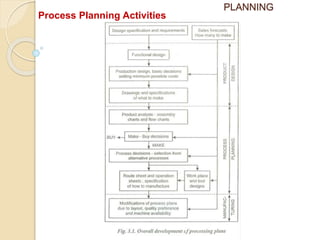
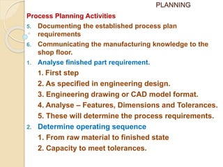
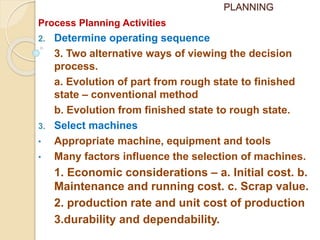
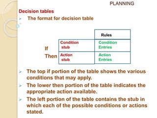
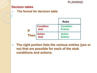
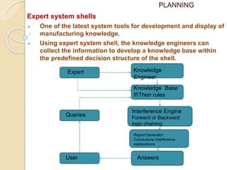
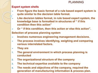
PLANNING
No one plans to fail but everyone fails to plan.
Machines should work, man should think.
The IBM pollyanna principle
I have six stalwart men; they taught me everything I know,
their names were What? And Where? and When? and Why?
and How? and Who? – Rudyard Kipling
Product development – Idea to customer usage – service.
Product development – design department.
To convert the design in to product – A manufacturing
plan is required.
The activity of developing a manufacturing plan is called
process planning.
Preparing set of instructions – describe how to
manufacture the parts of the product and the final product.
PLANNING
Task – Determining manufacturing operations required to
transform raw material to finished product as per plan.
Also known as operations planning
It is systematic determination of engineering processes
and systems to manufacture a product completely and
economically.
Def: “ An act of preparing a detailed processing
documentation for the manufacture of a piece part or
assembly”
According to American Society of Tool and Manufacturing
Engineers, - “Process planning is the systematic
determination of the methods by which a product is to be
manufactured economically and completely”
PLANNING
It consists of Devising, Selecting and Specifying
processes machine tools and other equipments to
transform the raw material into finished product as per
specifications.
Importance of process planning
1. Link between Design and Shop floor manufacturing
2. Determines how product will be manufactured
3. Important determinant of production cost and
profitability.
4. Determines capacity and delivery schedule.
Requirements
 In depth knowledge of process and equipment
capabilities, tooling availability, material processing
characteristics, related cost and shop practices.
PLANNING
Requirements
 Plan should be feasible, low cost and consistent
 Should facilitate feed back from manufacturing to
design.
Technological view of process planning
• Process planning is an intermediate stage between
designing the product and manufacturing it.
Details of a process plan
• A detailed process plan usually contains
1. Route sheet
2. Processes
3. Process parameters
4. Machines
5. Tools
PLANNING
Information required
1. Component and Assembly drawings and bill of material.
 Detailed description of part to be manufactured, raw
material specifications, dimensions and tolerances
required, surface finish and treatment required.
2. Machine and equipment details
 The various possible operations that can be
performed.
 Maximum and minimum dimensions that can be
machined on the machine.
 The accuracy of the machine that can be obtained.
 Available feed and speed of the machine.
3. Standard time for each operation and setup time for
each job.
4. Availability of machine equipment and tool.
PLANNING
Responsibilities of a process planning engineer
1. Interpreting part print analysis and symbols
2. Gathering the fundamental details such as
 Type of rough stock
 Dimensional tolerances
 Type of finish
 Production rate
 Production volume
 Scrap losses
 Down time
 Design changes etc.
3. Selecting the machining process
4. Selecting the proper machining with allied tooling
based on
 Required machine capability
 Set up time
PLANNING
Responsibilities of a process planning engineer
4. Selecting the proper machining with allied tooling
based on
 Required machine capability
 Set up time
 Practical lot size
 Quality of parts
 Cost of tooling
 Type of tooling
5. Sequencing the operations
6. Deciding on the inspection equipment in order to meet
the desired quality.
7. Determining the appropriate production tolerances.
8. Determining proper cutting tools and cutting condition.
9. Calculating overall time using work measurement
technique.
PLANNING
Factors affecting process planning
1. Volume of production
2. Skill and expertise of man power
3. Delivery dates for parts
4. Material specification
5. Accuracy and process capabilities of machines
6. Accuracy requirements of parts and products.
Process Planning Activities
1. Analysis of finished part requirements as specified in
the engineering design.
2. Determining the sequence of operation required.
3. Selecting the proper equipment to accomplish the
required operation.
4. Calculating the specific operation set up times and
cycle time on each machine.
PLANNING
Process Planning Activities
PLANNING
Process Planning Activities
5. Documenting the established process plan
requirements
6. Communicating the manufacturing knowledge to the
shop floor.
1. Analyse finished part requirement.
1. First step
2. As specified in engineering design.
3. Engineering drawing or CAD model format.
4. Analyse – Features, Dimensions and Tolerances.
5. These will determine the process requirements.
2. Determine operating sequence
1. From raw material to finished state
2. Capacity to meet tolerances.
PLANNING
Process Planning Activities
2. Determine operating sequence
3. Two alternative ways of viewing the decision
process.
a. Evolution of part from rough state to finished
state – conventional method
b. Evolution from finished state to rough state.
3. Select machines
• Appropriate machine, equipment and tools
• Many factors influence the selection of machines.
1. Economic considerations – a. Initial cost. b.
Maintenance and running cost. c. Scrap value.
2. production rate and unit cost of production
3.durability and dependability.
PLANNING
Process Planning Activities
3. Select machines
4. Lower process rejection.
5. Minimum set up and put away time.
6. longer productive life of machines.
7. functional versatility – ability to perform
more than one operation.
 Knowledge about alternative machines.
 Make or buy decision.
 Break even analysis as a tool.
4. Material selection parameters
 Sound and economical
 Parameters affecting selection
1. Function – Physical, Mechanical, Electrical,
Thermal and Chemical.
PLANNING
Process Planning Activities
4. Material selection parameters
 Parameters affecting selection
2. Appearance.
3.Reliability
4. Service life
5. Compatibility
6. Produceability
7. Environment
8. Cost.
5. Calculate processing time
 set up time and cycle time
 set up time – knowledge of tools and steps
required to prepare the machine
 Calculation of part processing time – sequence of
operation – called “out planning”
PLANNING
Process Planning Activities
5. Calculate processing time
 Part loading, machine indexing, unloading etc.
Should be considered.
 Allowances
 Standard time and standard cost
6. Document and process planning
 Operation sheet, Route sheet, Instruction sheet
Traveller or Planner
 Route sheet provide the following information
1. Part identification ( Numbers and Names)
2. Description of the processing steps in each
operation.
PLANNING
Route sheet
PLANNING
Process Planning Activities
6. Document and process planning
 Route sheet provide the following information
3. Operation sequence and machines
4. Std. Set up and cycle time.
5. Tooling requirements for each operation.
6. Production control information.
Reasons for process documentation
1. To have record on how a part is processed –
Future parts with similar design
2. Cost estimation.
3. To communicate.
PLANNING
Process Planning Activities
7. Communicate process knowledge
 Final step – To communicate the
manufacturing information to the shop floor
people (operation sheet and process drawing)
 To ensure – part will be processed by the most
possible economical way.
 Process documentation and corresponding
communication provide basis for improved
part consistency and quality in manufacturing.
PLANNING
Approaches to Process Planning
1. Manual approach
2. Computer Aided Process Planning
i) Retrieval CAPP system
ii) Generative CAPP system
Manual Process Planning
 Prepared manually
 Tasks
1. Interpreting Engineering Drawings
2. Machining process selection
3. Equipment selection
4. Operation sequence
5. Shop practices
PLANNING
Approaches to Process Planning
Manual Process Planning
 Very much dependent on the skill, judgement
and experience of the process planner
Advantages
1. Very much suitable for small scale industries
2. Method is highly feasible
3. Requires low investment cost
Disadvantages
1. Complex and time consuming – job requires
large amount of data
2. Requires skilled process planner
3. More possibility of human error – skill,
experience and judgement.
PLANNING
Approaches to Process Planning
Manual Process Planning
Disadvantages
4. It increase paper work
5. Inconsistent process plan results in reduced
productivity.
Computer Aided Process Planning (CAPP)
 Overcome the drawbacks of manual PP
 Can reduce routine clerical work
 Possibility of rational, consistent and optimal
plans.
 CAPP provides interface between CAD & CAM
PLANNING
Approaches to Process Planning
Benefits of Computer Aided Process Planning
1. Process rationalization and standardization
2. Productivity improved
3. Product cost reduction
4. Elimination of human error
5. Reduction in time
6. Reduced clerical work and paper work
7. Improved legibility
8. Faster response to engineering changes
9. Incorporation of other appropriate programs
PLANNING
Approaches to Process Planning
 Retrieval or variant CAPP system
 Generative CAPP system
1. Retrieval CAPP system
 Widely used in machining applications
 Basic idea – similar parts – similar plan
 In this system process plan for a part is created by
recalling, identifying and retrieving an existing plan for
a similar part, and making the necessary modification
for the new part.
 Retrieval CAPP system is based on the principle of
Group technology (GT) – part classification and coding
 Each part family has a standard plan (Route sheet) is
prepared and stored in computer.
 Through classification and coding a code number is
generated.
PLANNING
Retrieval CAPP system
PLANNING
Approaches to Process Planning
1. Retrieval CAPP system
 Codes are used to identify the part family and
associated standard plan.
 The standard plan is retrieved and edited for the new
part.
Advantages
 With standard plan – variety of parts can be planned
 Comparatively simple programming and installation
 The system is understandable and the planner has the
control of the final plan.
 It is easy to learn and easy to use.
Drawbacks
1. The components to be planned are limited to similar
parts previously planned
PLANNING
Approaches to Process Planning
1. Retrieval CAPP system
Drawbacks
2. Experienced process planners are still required to
modify the standard plan for the specific components.
 Retrieval CAPP system has the capacity to alter an
existing plan. That's why it is also known as “Variant
CAPP system”
Generative CAPP system
 In generative approach – The computer is used to
synthesize or generate each individual process plan
automatically and with out reference to previous plan.
 Generates process plan based on decision logics and
pre-coded algorithms.
 The computer stores the rules of manufacturing and
equipment capability. ( Not any group of process Plan)
PLANNING
Approaches to Process Planning
2.Generative CAPP system
 When using a system, a specific process plan for a
specific part can be generated without any involvement
of a process planner.
 Human role in running the system – i) Inputting the GT
code of the given part design.
 ii) Monitoring the function
Components of a Generative CAPP system
1. A part description – series of component
characteristics ( Geometric features, dimensions,
tolerances and surface conditions)
2. A sub system to define the machining parameters Ex:
analytical results of cutting parameters, loop-up tables
etc.
3. A sub system to select and sequence the individual
operations.
PLANNING
Approaches to Process Planning
Components of a Generative CAPP system
Decision logic – to associate appropriate operations
with features of a component.
Heuristic & algorithms are used to calculate the
operation steps, time and sequence.
4. A data base of available machines and tools.
5. A report generator which prepares process plan report.
Advantages of Generative CAPP
1. It can generate consistent process plan rapidly.
2. New components can be planned
3. Potential for integrating with CAM to provide detailed
control information.
Drawbacks
1. Complex and very difficult to develop.
Commercial Generative CAPP – “APPAS”, CMPP, XCAP
& XPLAN
PLANNING
Developing Manufacturing Logic & Knowledge
 To support a process planning system – the acquisition
and manufacturing knowledge is very essential.
 Generally agreed – knowledge structure to be
determined prior to any type of program coding or data
presentation.
 A sound knowledge structure will help to ensure error
reduction, debugging case, clarity and future
modification.
 Therefore production engineers – need to develop a
knowledge structure format.
 That knowledge structure format can be interactive
process.
 The KSF will emphasize what question to ask and what
data to collect to support a standardize format.
PLANNING
Developing Manufacturing Logic & Knowledge
 Need for system tools to acquire and document
knowledge in such a manner – to bring together,
analyze and display the resulting manufacturing
knowledge in a consistent and well structured manner.
 Three commonly used tools for acquiring and
documenting knowledge are
1. Flow charts
2. Decision table
3. Expert system shells.
i. Flow chats
 One of the most commonly used tool for the collection
and display of manufacturing knowledge.
PLANNING
Flow chats
PLANNING
Developing Manufacturing Logic & Knowledge
i. Flow chats
 Widely used because they are commonly taught in
computer programming subjects.
Disadvantages
1. Flow charts focus on process rather than the structure
of decision logic.
2. Flow charts provide no check against incompleteness,
contradiction and redundancy.
3. Flow charts often employ abbreviations and hence they
are defective for effective communication of
knowledge.
Decision tables
 Decision tables are system or logic tools to bring
together, analyse and display complex decision logic in
such a way that its meaning can be readily grasped.
PLANNING
Decision tables
 The format for decision table
If
Then
 The top if portion of the table shows the various
conditions that may apply.
 The lower then portion of the table indicates the
appropriate action available.
 The left portion of the table contains the stub in
which each of the possible conditions or actions
stated.
Condition
stub
Action
stub
Action
Entries
Condition
Entries
Rules
PLANNING
Decision tables
 The format for decision table
If
Then
 The right portion lists the various entries (yes or
no) that are possible for each of the stub
conditions and actions.
Condition
stub
Action
stub
Action
Entries
Condition
Entries
Rules
PLANNING
Benefits of Decision tables
1. Decision table assist production engineers in thinking
through a problem thoroughly and presenting its
resolution in a systematic and rationally structured
format.
2. Ensure accuracy, eliminate redundancy and avoid
contradiction as a by product.
3. Assists instating the problem, agreeing on criteria,
stating alternatives and accepting action between
criteria and alternatives.
4. decision tables provide knowledge structure and
readable documentation as a by product.
PLANNING
Expert system shells
 One of the latest system tools for development and display of
manufacturing knowledge.
 Using expert system shell, the knowledge engineers can
collect the information to develop a knowledge base within
the predefined decision structure of the shell.
Knowledge
Engineer
Knowledge Base
If/Then rules
Interference Engine
Forward or Backward
logic chaining
Report Generator
Conclusions interference
explanations
Answers
Expert
Queries
User
PLANNING
Expert system shells
 From figure the basic format of a rule based expert system is
quite similar to the decision table format.
 Like decision tables format, in rule based expert system, the
knowledge base is formatted in structures of “ if this
condition then this action”
 Or “ if this condition, then this action or else this action”.
Selection of process planning system
 Involves numerous engineering management decisions.
 The process involves identifying, weighing and comparing
various interrelated factors.
 They are
1. The general environment in which process planning is
conducted
2. The organizational structure of the company
3. The technical expertise available to the company
4. The needs and objectives of the company, required the
generation of manufacturing information & process plan.

PROCESS PLANNING 1.pptx

  • 1.
    PLANNING No one plansto fail but everyone fails to plan. Machines should work, man should think. The IBM pollyanna principle I have six stalwart men; they taught me everything I know, their names were What? And Where? and When? and Why? and How? and Who? – Rudyard Kipling Product development – Idea to customer usage – service. Product development – design department. To convert the design in to product – A manufacturing plan is required. The activity of developing a manufacturing plan is called process planning. Preparing set of instructions – describe how to manufacture the parts of the product and the final product.
  • 2.
    PLANNING Task – Determiningmanufacturing operations required to transform raw material to finished product as per plan. Also known as operations planning It is systematic determination of engineering processes and systems to manufacture a product completely and economically. Def: “ An act of preparing a detailed processing documentation for the manufacture of a piece part or assembly” According to American Society of Tool and Manufacturing Engineers, - “Process planning is the systematic determination of the methods by which a product is to be manufactured economically and completely”
  • 3.
    PLANNING It consists ofDevising, Selecting and Specifying processes machine tools and other equipments to transform the raw material into finished product as per specifications. Importance of process planning 1. Link between Design and Shop floor manufacturing 2. Determines how product will be manufactured 3. Important determinant of production cost and profitability. 4. Determines capacity and delivery schedule. Requirements  In depth knowledge of process and equipment capabilities, tooling availability, material processing characteristics, related cost and shop practices.
  • 4.
    PLANNING Requirements  Plan shouldbe feasible, low cost and consistent  Should facilitate feed back from manufacturing to design. Technological view of process planning • Process planning is an intermediate stage between designing the product and manufacturing it. Details of a process plan • A detailed process plan usually contains 1. Route sheet 2. Processes 3. Process parameters 4. Machines 5. Tools
  • 5.
    PLANNING Information required 1. Componentand Assembly drawings and bill of material.  Detailed description of part to be manufactured, raw material specifications, dimensions and tolerances required, surface finish and treatment required. 2. Machine and equipment details  The various possible operations that can be performed.  Maximum and minimum dimensions that can be machined on the machine.  The accuracy of the machine that can be obtained.  Available feed and speed of the machine. 3. Standard time for each operation and setup time for each job. 4. Availability of machine equipment and tool.
  • 6.
    PLANNING Responsibilities of aprocess planning engineer 1. Interpreting part print analysis and symbols 2. Gathering the fundamental details such as  Type of rough stock  Dimensional tolerances  Type of finish  Production rate  Production volume  Scrap losses  Down time  Design changes etc. 3. Selecting the machining process 4. Selecting the proper machining with allied tooling based on  Required machine capability  Set up time
  • 7.
    PLANNING Responsibilities of aprocess planning engineer 4. Selecting the proper machining with allied tooling based on  Required machine capability  Set up time  Practical lot size  Quality of parts  Cost of tooling  Type of tooling 5. Sequencing the operations 6. Deciding on the inspection equipment in order to meet the desired quality. 7. Determining the appropriate production tolerances. 8. Determining proper cutting tools and cutting condition. 9. Calculating overall time using work measurement technique.
  • 8.
    PLANNING Factors affecting processplanning 1. Volume of production 2. Skill and expertise of man power 3. Delivery dates for parts 4. Material specification 5. Accuracy and process capabilities of machines 6. Accuracy requirements of parts and products. Process Planning Activities 1. Analysis of finished part requirements as specified in the engineering design. 2. Determining the sequence of operation required. 3. Selecting the proper equipment to accomplish the required operation. 4. Calculating the specific operation set up times and cycle time on each machine.
  • 9.
  • 10.
    PLANNING Process Planning Activities 5.Documenting the established process plan requirements 6. Communicating the manufacturing knowledge to the shop floor. 1. Analyse finished part requirement. 1. First step 2. As specified in engineering design. 3. Engineering drawing or CAD model format. 4. Analyse – Features, Dimensions and Tolerances. 5. These will determine the process requirements. 2. Determine operating sequence 1. From raw material to finished state 2. Capacity to meet tolerances.
  • 11.
    PLANNING Process Planning Activities 2.Determine operating sequence 3. Two alternative ways of viewing the decision process. a. Evolution of part from rough state to finished state – conventional method b. Evolution from finished state to rough state. 3. Select machines • Appropriate machine, equipment and tools • Many factors influence the selection of machines. 1. Economic considerations – a. Initial cost. b. Maintenance and running cost. c. Scrap value. 2. production rate and unit cost of production 3.durability and dependability.
  • 12.
    PLANNING Process Planning Activities 3.Select machines 4. Lower process rejection. 5. Minimum set up and put away time. 6. longer productive life of machines. 7. functional versatility – ability to perform more than one operation.  Knowledge about alternative machines.  Make or buy decision.  Break even analysis as a tool. 4. Material selection parameters  Sound and economical  Parameters affecting selection 1. Function – Physical, Mechanical, Electrical, Thermal and Chemical.
  • 13.
    PLANNING Process Planning Activities 4.Material selection parameters  Parameters affecting selection 2. Appearance. 3.Reliability 4. Service life 5. Compatibility 6. Produceability 7. Environment 8. Cost. 5. Calculate processing time  set up time and cycle time  set up time – knowledge of tools and steps required to prepare the machine  Calculation of part processing time – sequence of operation – called “out planning”
  • 14.
    PLANNING Process Planning Activities 5.Calculate processing time  Part loading, machine indexing, unloading etc. Should be considered.  Allowances  Standard time and standard cost 6. Document and process planning  Operation sheet, Route sheet, Instruction sheet Traveller or Planner  Route sheet provide the following information 1. Part identification ( Numbers and Names) 2. Description of the processing steps in each operation.
  • 15.
  • 16.
    PLANNING Process Planning Activities 6.Document and process planning  Route sheet provide the following information 3. Operation sequence and machines 4. Std. Set up and cycle time. 5. Tooling requirements for each operation. 6. Production control information. Reasons for process documentation 1. To have record on how a part is processed – Future parts with similar design 2. Cost estimation. 3. To communicate.
  • 17.
    PLANNING Process Planning Activities 7.Communicate process knowledge  Final step – To communicate the manufacturing information to the shop floor people (operation sheet and process drawing)  To ensure – part will be processed by the most possible economical way.  Process documentation and corresponding communication provide basis for improved part consistency and quality in manufacturing.
  • 18.
    PLANNING Approaches to ProcessPlanning 1. Manual approach 2. Computer Aided Process Planning i) Retrieval CAPP system ii) Generative CAPP system Manual Process Planning  Prepared manually  Tasks 1. Interpreting Engineering Drawings 2. Machining process selection 3. Equipment selection 4. Operation sequence 5. Shop practices
  • 19.
    PLANNING Approaches to ProcessPlanning Manual Process Planning  Very much dependent on the skill, judgement and experience of the process planner Advantages 1. Very much suitable for small scale industries 2. Method is highly feasible 3. Requires low investment cost Disadvantages 1. Complex and time consuming – job requires large amount of data 2. Requires skilled process planner 3. More possibility of human error – skill, experience and judgement.
  • 20.
    PLANNING Approaches to ProcessPlanning Manual Process Planning Disadvantages 4. It increase paper work 5. Inconsistent process plan results in reduced productivity. Computer Aided Process Planning (CAPP)  Overcome the drawbacks of manual PP  Can reduce routine clerical work  Possibility of rational, consistent and optimal plans.  CAPP provides interface between CAD & CAM
  • 21.
    PLANNING Approaches to ProcessPlanning Benefits of Computer Aided Process Planning 1. Process rationalization and standardization 2. Productivity improved 3. Product cost reduction 4. Elimination of human error 5. Reduction in time 6. Reduced clerical work and paper work 7. Improved legibility 8. Faster response to engineering changes 9. Incorporation of other appropriate programs
  • 22.
    PLANNING Approaches to ProcessPlanning  Retrieval or variant CAPP system  Generative CAPP system 1. Retrieval CAPP system  Widely used in machining applications  Basic idea – similar parts – similar plan  In this system process plan for a part is created by recalling, identifying and retrieving an existing plan for a similar part, and making the necessary modification for the new part.  Retrieval CAPP system is based on the principle of Group technology (GT) – part classification and coding  Each part family has a standard plan (Route sheet) is prepared and stored in computer.  Through classification and coding a code number is generated.
  • 23.
  • 24.
    PLANNING Approaches to ProcessPlanning 1. Retrieval CAPP system  Codes are used to identify the part family and associated standard plan.  The standard plan is retrieved and edited for the new part. Advantages  With standard plan – variety of parts can be planned  Comparatively simple programming and installation  The system is understandable and the planner has the control of the final plan.  It is easy to learn and easy to use. Drawbacks 1. The components to be planned are limited to similar parts previously planned
  • 25.
    PLANNING Approaches to ProcessPlanning 1. Retrieval CAPP system Drawbacks 2. Experienced process planners are still required to modify the standard plan for the specific components.  Retrieval CAPP system has the capacity to alter an existing plan. That's why it is also known as “Variant CAPP system” Generative CAPP system  In generative approach – The computer is used to synthesize or generate each individual process plan automatically and with out reference to previous plan.  Generates process plan based on decision logics and pre-coded algorithms.  The computer stores the rules of manufacturing and equipment capability. ( Not any group of process Plan)
  • 26.
    PLANNING Approaches to ProcessPlanning 2.Generative CAPP system  When using a system, a specific process plan for a specific part can be generated without any involvement of a process planner.  Human role in running the system – i) Inputting the GT code of the given part design.  ii) Monitoring the function Components of a Generative CAPP system 1. A part description – series of component characteristics ( Geometric features, dimensions, tolerances and surface conditions) 2. A sub system to define the machining parameters Ex: analytical results of cutting parameters, loop-up tables etc. 3. A sub system to select and sequence the individual operations.
  • 27.
    PLANNING Approaches to ProcessPlanning Components of a Generative CAPP system Decision logic – to associate appropriate operations with features of a component. Heuristic & algorithms are used to calculate the operation steps, time and sequence. 4. A data base of available machines and tools. 5. A report generator which prepares process plan report. Advantages of Generative CAPP 1. It can generate consistent process plan rapidly. 2. New components can be planned 3. Potential for integrating with CAM to provide detailed control information. Drawbacks 1. Complex and very difficult to develop. Commercial Generative CAPP – “APPAS”, CMPP, XCAP & XPLAN
  • 28.
    PLANNING Developing Manufacturing Logic& Knowledge  To support a process planning system – the acquisition and manufacturing knowledge is very essential.  Generally agreed – knowledge structure to be determined prior to any type of program coding or data presentation.  A sound knowledge structure will help to ensure error reduction, debugging case, clarity and future modification.  Therefore production engineers – need to develop a knowledge structure format.  That knowledge structure format can be interactive process.  The KSF will emphasize what question to ask and what data to collect to support a standardize format.
  • 29.
    PLANNING Developing Manufacturing Logic& Knowledge  Need for system tools to acquire and document knowledge in such a manner – to bring together, analyze and display the resulting manufacturing knowledge in a consistent and well structured manner.  Three commonly used tools for acquiring and documenting knowledge are 1. Flow charts 2. Decision table 3. Expert system shells. i. Flow chats  One of the most commonly used tool for the collection and display of manufacturing knowledge.
  • 30.
  • 31.
    PLANNING Developing Manufacturing Logic& Knowledge i. Flow chats  Widely used because they are commonly taught in computer programming subjects. Disadvantages 1. Flow charts focus on process rather than the structure of decision logic. 2. Flow charts provide no check against incompleteness, contradiction and redundancy. 3. Flow charts often employ abbreviations and hence they are defective for effective communication of knowledge. Decision tables  Decision tables are system or logic tools to bring together, analyse and display complex decision logic in such a way that its meaning can be readily grasped.
  • 32.
    PLANNING Decision tables  Theformat for decision table If Then  The top if portion of the table shows the various conditions that may apply.  The lower then portion of the table indicates the appropriate action available.  The left portion of the table contains the stub in which each of the possible conditions or actions stated. Condition stub Action stub Action Entries Condition Entries Rules
  • 33.
    PLANNING Decision tables  Theformat for decision table If Then  The right portion lists the various entries (yes or no) that are possible for each of the stub conditions and actions. Condition stub Action stub Action Entries Condition Entries Rules
  • 34.
    PLANNING Benefits of Decisiontables 1. Decision table assist production engineers in thinking through a problem thoroughly and presenting its resolution in a systematic and rationally structured format. 2. Ensure accuracy, eliminate redundancy and avoid contradiction as a by product. 3. Assists instating the problem, agreeing on criteria, stating alternatives and accepting action between criteria and alternatives. 4. decision tables provide knowledge structure and readable documentation as a by product.
  • 35.
    PLANNING Expert system shells One of the latest system tools for development and display of manufacturing knowledge.  Using expert system shell, the knowledge engineers can collect the information to develop a knowledge base within the predefined decision structure of the shell. Knowledge Engineer Knowledge Base If/Then rules Interference Engine Forward or Backward logic chaining Report Generator Conclusions interference explanations Answers Expert Queries User
  • 36.
    PLANNING Expert system shells From figure the basic format of a rule based expert system is quite similar to the decision table format.  Like decision tables format, in rule based expert system, the knowledge base is formatted in structures of “ if this condition then this action”  Or “ if this condition, then this action or else this action”. Selection of process planning system  Involves numerous engineering management decisions.  The process involves identifying, weighing and comparing various interrelated factors.  They are 1. The general environment in which process planning is conducted 2. The organizational structure of the company 3. The technical expertise available to the company 4. The needs and objectives of the company, required the generation of manufacturing information & process plan.