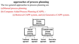
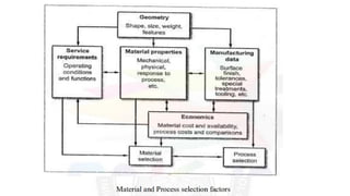
Unit 5 Process Planning
Introduction- methods of process planning,
drawing interpretation,
material evaluation,
steps in process selection,
production equipment and tooling selection,
process parameters calculation for various production processes,
Selection of jigs and fixtures,
selection of quality assurance methods,
documents for process planning,
Economics of process planning,
case studies.
PROCESS
• Conversion of a work-piece from its initial form to a final form predetermined
(usually by a design engineer)
• Group of action to achieve the output in accordance with a specified measure
of effectiveness.
• Various manufacturing processes:
Casting : Establishing
Forming: Moving of material
Machining: Subtractive / Removing Technique
Fabrication / Welding: Additive / Joining Technique
Finishing Process: Final / aesthetic aspects
Manufacturing:
the making of products from raw materials using various processes, equipment, operations and
manpower according to a detailed plan.
Process planning:
accordingly to the American Society
of Tool & Manufacturing engineers
Process planning can also be defined as
the systematic determination of the
methods by which a product is to be
manufactured economically and
competitively.
It consists of devising, selecting and specifying
processes,
machine tools and other equipment
Tool
to convert raw material into finished and
assembled products.
PROCESS PLANNING
comprises the selection and sequencing of processes and operations to transform a
chosen raw material into a finished component.
• It is the act of preparing detailed work instructions to produce a component.
This includes the selection of manufacturing processes .
and operations, production equipment,
tooling and jigs and fixtures.
• It will also normally include
determining manufacturing
parameters and specifying criteria
for the selection of quality assurance
methods to ensure product quality
Factors affect process planning:
1. Availability of machine 2. Delivery date
3. Quantity to be produced 4. Quality standards
Reasons for process documentation
1. To have a record on how a part is processed in order to plan future parts with similar design
requirements in a consistent manner
2. To provide a record for future job quoting, cost estimating, and standard costing systems
3. To act as a vehicle for communication
What are the information required to do process planning?
(a) Quantity of work to be done along with product specifications.
(b) Quality of work to be completed.
(c) Availability of equipment, tools and personnel.
(d) Sequence in which operations will be performed on the raw material.
(e) Names of equipment on which the operations will be performed.
(f) Standard time for each operation.
(g) The time of operations will be performed.
approaches of process planning
The two general-approaches to process planning are
(a)Manual process planning
(b) Computer Aided Process Planning (CAPP). -
(i) Retrieval CAPP system, and (ii) Generative CAPP system.
Manual Process Planning (MAPP)
Traditional Approach:
Step 1: He looks at the drawing and uses his experience of manufacturing methods,
combined with knowledge of the types of resource available, to decide how the
component or assembly should be made.
Step 2: For each element of each operation, he refers to manuals to ascertain the
company's recommended tools, feeds and speeds for the particular material on the
selected machine. Also using manuals, the planned times for all the handling and
machining elements involved are ascertained. These are then used to synthesize the
set-up time and the time per unit quantity for each operation.
•All of the above particulars in Step 1 are documented in the process planning
layout, also known as a routing sheet, which lists all the operations. For each
operation there is a methods or operations list, which specifies all the details referred
to in Step 2
Workbook Approach:
It is a derivative of the traditional approach.
This is considered a more efficient approach.
It involves developing workbooks of pre-determined sequences of operations
for given types of work pieces.
After having carried out the drawing interpretation and identified the
manufacturing processes required, the predetermined sequence of operations can
be selected from the workbook and incorporated into the process plan
Computer Aided Process Planning
In order to overcome the drawbacks of manual process planning, the computer-aided
process planning (CAPP) is used.
With the use of computers in the process planning, one can reduce the routine clerical
work of manufacturing engineers.
Also, it provides the opportunity to generate rational, consistent and optimal plans. It
represents the link between design and manufacturing in a CAD/CAM system.
Computer Aided Process Planning can be categorized in two major areas;
variant planning, where library retrieval procedures are applied to find standard
plans for similar components, and
generative process planning, where plans are generated automatically for new
components without reference to existing plans.
The latter system is most desirable but also the most difficult way of performing
CAPP.
Variant or Retrieval CAPP
 computer makes a search of its storage or a data
base or a no. of standard or completed process
plans that have been previously developed by the
company’s process planners.
The development of the data base of these
process plans requires substantial knowledge of
machining, time and efforts.
Using the current design data supplied by the
CAD system, (after a component has been
designed and dimensioned), it searches for a
process plan that was based on a part of similar
design. (This search can make effective use of GT,
Group Technology, design coding to simplify the
search for similar part design).
• The process plan retrieved is then modified or suitably varied (i.e., altered) by the
process planner, to suit the exact requirements of the current part design.
• The use of Computer and Group Procedure for developing the Retrieval type
Technology (GT) to search for the most appropriate or similar part design, and to
retrieve the process plan for that design, significantly reduces the work required of
the process planners.
• This approach of process planning is also known as Retrieval CAPP system.
This is based on the principles of Group Technology and parts classification and
coding.
• One of the pre-requisites for implementation of this method is that the industries
must develop and maintain a large computer data base of standard completed
process plans. In addition, the part designs are to be developed using CAD
systems.
Generative Method of Process Planning (Generative CAPP System)
• A process plan is created from scratch without human intervention.
• Computer uses the stored data (manufacturing and design) to generate
process plan that could be used to manufacture the current part.
• It searches this list for the one which optimizes the cost function. This
method always yields the optimum process plan for manufacturing a
particular part.
• However, it has a very high cost in terms of time and computer processing
expenses.
• To repeat this for every feasible process plan or a part can become very
costly.
Advantages
1 Consistent process plans can be generated rapidly.
2. New components can be planned as easily as existing components.
3. It has potential for integrating with an automated manufacturing facility to
provide detailed control information.
Drawing Interpretation
The drawing interpretation is the starting point for the process selection.
From drawing interpretation, the design requirements are expressed as
constraints on material, shape, size, tolerance, roughness and other process
related parameters.
The drawing interpretation can be presented under three different analysis and
outputs
1. Geometry analysis
2. Manufacturing information
3. Material evaluation and output from drawing interpretation
The Process Shape Matrix
The first analysis geometry analysis. The selection of manufacturing processes depends on the
geometry and shape of the component/ product.
The process shape matrix showing the links between component geometry and different
manufacturing processes.
The second analysis and output from drawing interpretation is the manufacturing information.
The manufacturing information derived from drawing interpretation include:
Dimensional and geometric tolerances Limits and fits
Surface finish requirements Tolerances specifications
Tool references Gauge references
Special material treatment
The third and final analysis and output from drawing interpretation is the material evaluation.
Particular attention should be paid to instances where there are combinations of- dimensional
tolerances and geometrical tolerances and/or surface finish specifications.
Drawing interpretation
contain a variety of information which can help assess the processing
requirements.
 The interpretation of the drawing will include assessing the part geometry,
dimensions and associated tolerances, geometric tolerances, surface finish
specifications, the material specification and the number of parts required
Drawing Interpretation Uses
• To identify the relevant drawing information that helps the process planner
identify critical processing factors.
• Identify appropriate supplementary information from the drawing to aid the
process planning;
• Identify and interpret dimensional information from the drawing;
• Identify and interpret geometric information from the drawing;
• Identify the critical processing factors for the component from the dimensional
and geometric information.
1. to identify the relevant drawing information that helps the process planner
identify critical processing factors.
Engineering Drawing -
Detail Drawing; Assembly drawing; combined drawing
2. Identifying useful supplementary information apart from geometry material
and specification;
•notes on special material treatments;
•notes on surface finish; general tolerances;
•keys to geometrical tolerances;
•notes on equivalent parts; notes on screw thread forms;
•tool references; gauge references;
•quantity to be produced; parts lists (in the case of assembly drawings).
3. Identify and interpret dimensional information from the drawing
Dimensional Tolerances Bilateral / Unilateral tolerances
Limits & Fits
Hole basis • Shaft basis
4. identify and interpret geometric information from the drawing
Geometrical tolerances
To mention the geometry allowance to the manufacturing product.
Material evaluation
Classification of materials - Metals (ferrous, nonferrous), Ceramics, Polymers,
Composites and semi-conducter
Basic material properties – mechanical, physical, etc.
material selection process
material selection method
Material evaluation method – shape/ geometry, property required, manufacturing consideration,
Manufacturing Processes – casting, forming and shaping, machining, joining, etc
material selection process:
design and development of a new product
modification of an existing product
prime consideration is the shapes / features required:
Flat surface
Parts with cavity
parts with sharp corner
Thin hollow shape
Tubular shape
Surface texture
Three-stages are in evaluation procedure:
shape or geometry considerations
material property requirements
manufacturing consideration
STEPS IN PROCESS SELECTION
A process is a method of shaping, joining, or finishing a material.
It is important to choose the right manufacturing process at the design stage
itself. The selection of right manufacturing process depends on the materials to
be used, on its size, shape and precision and number of parts to be made.
Primary Processes Vs Secondary Processes
Primary processes create shapes. casting, moldings, deformation, powder
methods, methods of forming composites, special methods and rapid prototyping.
Secondary processes modify shapes and properties.
(i) machining, which adds features to an already shaped body
(ii) heat treatment, which enhances surface or build properties.
The three broad manufacturing process families are:
1. Shaping, 2. Joining, and 3. Finishing.
Classification of Manufacturing Processes
FACTORS IN PROCESS SELECTION
•The materials selected in the previous stage will influence the selection of the
manufacturing processes to be employed. Some of the factors to be considered in
the selection of Manufacturing processes include:
1.Material form 2.Component size and weight 3.Economic considerations
4.Dimensional and geometric accuracy 5.Surface finish specification
6.Batch size 7.Production rate
STAGES OF PROCESS SELECTION:
The process selection involves the following four stages:
Stage 1: Drawing Interpretation
Stage 2: Identification of critical processing factors
Stage 3: Comparison potential manufacturing processes
Stage 4: Identification of suitable processes
General Guidelines for Process Selection The following general guidelines can be
considered while selecting the manufacturing processes
(i)Identify a manufacturing process which can provide the required dimensional/
geometric accuracy and surface finish.
(ii) To allow more choice of manufacturing processes, specify the maximum possible
tolerances and surface finish variation for products
(iii) Employ prototypes to verify and validate the potential manufacturing under
consideration.
(iv) Perform a comparison analysis of the potential manufacturing processes under
consideration, taking into account the variation in assembly costs for different processes.
selection of jigs and fixtures
The main reasons for the use of jigs and fixtures are:
 components can be produced quicker;
greater interchangeability is obtained due to repeatability of manufacture which subsequently
reduces assembly time;
accuracy can be easily obtained and maintained;
 unskilled or semi-skilled labour may be used on a machine, resulting in reduced manufacturing
costs
Selection of jigs and fixtures:
The aim is to introduce the design and/or selection of work holding devices for particular operations.
define and differentiate between a jig and a fixture in terms of their functionality;
select an appropriate type of jig or fixture for a given component based on the operations and processes
‟
specified for its manufacture;
apply the basic principles of location and clamping for a given component;
apply the basic principles of jig and fixture design and produce a general arrangement drawing for a given
component;
Identify other types of work holders used in component manufacture.
PROCESS PLANNING ECONIMICS
Any process planning must have the knowledge of the economic aspects to be considered while
designing a process plan. Before design a process plan, one must analyse the following :
(a) What type of machine is required?
(b) What is the production capacity of the machine?
(c) Existing machine/new machines.
(d) What is the tooling cost? Planning
(e) Estimating material cost.
(f) Estimating production rates.
Machine Selection
The machine selection process plays an important role in reducing the cost of production. Machine selection will effect
the following economic factors considering :
(a)Tooling cost
(b)(b) Set up cost
(c)(c) Production cost
(d)(d) Labour cost
Machine selection data will be collected and analyzed with the aid of Break-Even Chart and Payback Period Method.
Machine Selection
The machine selection process plays an important role in reducing the cost of
production. Machine selection will effect the following economic factors
considering :
(a)Tooling cost
(b)(b) Set up cost
(c)(c) Production cost
(d)(d) Labour cost
Machine selection data will be collected and analyzed with the aid of Break-Even
Chart and Payback Period Method.
Process documentation
Process documentation is nothing but the information collected and prepared about a post
production, production costs, ordering costs, tooling cost, purchase orders, total process,
assemblies through which a material moves from raw material stage to finished goods stage.
There are various types of documents used in the manufacturing industries, which are :
(a)Route sheet, (b) Operation sheet, (c) Work order, and (d) Purchase requisition
Route Sheet
It is a document, consists of information about part name, part number and the route through which
operational processes it goes to carry the required operations, etc. The route sheet also comprises
of brief description about the each operation, required tools, on which machine the operation is to
be carried, etc.
Operation Sheet
It is the document consists of information about a machine operator, drawing of required part,
tolerance levels of a product and the quality requirements of the product and processes, etc.
This information is utilised by tool room personnel, production and quality personnel. This
document is also known as process sheet.
Work Order
It is very important document or a written requisite for making various parts, tools, assemblies,
raw materials and funds required for manufacturing a particular product. Before manufacturing
a product this work order should be approved by the various authorities. Once the senior
authorities approved then the work order will be released for production of a tool, part,
assembly or a product.
There are different types of work orders will be :
(a) Tool and die making work order.
(b) Part production work order.
(c) Assembly work order.
Purchase Requisitions
•It is a document comprising information about the parts or components to be purchased
from out side companies or vendors.
•Mostly the authorities approve these requisitions is purchase and materials management.
•When ever a purchase requisition releases, one should attach a work order along with, so that
the information about the using department will be available. This will minimize the delay in
authorizing a purchase requisition
PROCESS PLANNING. steps in process selection

PROCESS PLANNING. steps in process selection

  • 1.
    Unit 5 ProcessPlanning Introduction- methods of process planning, drawing interpretation, material evaluation, steps in process selection, production equipment and tooling selection, process parameters calculation for various production processes, Selection of jigs and fixtures, selection of quality assurance methods, documents for process planning, Economics of process planning, case studies.
  • 2.
    PROCESS • Conversion ofa work-piece from its initial form to a final form predetermined (usually by a design engineer) • Group of action to achieve the output in accordance with a specified measure of effectiveness. • Various manufacturing processes: Casting : Establishing Forming: Moving of material Machining: Subtractive / Removing Technique Fabrication / Welding: Additive / Joining Technique Finishing Process: Final / aesthetic aspects Manufacturing: the making of products from raw materials using various processes, equipment, operations and manpower according to a detailed plan.
  • 3.
    Process planning: accordingly tothe American Society of Tool & Manufacturing engineers Process planning can also be defined as the systematic determination of the methods by which a product is to be manufactured economically and competitively. It consists of devising, selecting and specifying processes, machine tools and other equipment Tool to convert raw material into finished and assembled products.
  • 4.
    PROCESS PLANNING comprises theselection and sequencing of processes and operations to transform a chosen raw material into a finished component. • It is the act of preparing detailed work instructions to produce a component. This includes the selection of manufacturing processes . and operations, production equipment, tooling and jigs and fixtures. • It will also normally include determining manufacturing parameters and specifying criteria for the selection of quality assurance methods to ensure product quality
  • 5.
    Factors affect processplanning: 1. Availability of machine 2. Delivery date 3. Quantity to be produced 4. Quality standards Reasons for process documentation 1. To have a record on how a part is processed in order to plan future parts with similar design requirements in a consistent manner 2. To provide a record for future job quoting, cost estimating, and standard costing systems 3. To act as a vehicle for communication What are the information required to do process planning? (a) Quantity of work to be done along with product specifications. (b) Quality of work to be completed. (c) Availability of equipment, tools and personnel. (d) Sequence in which operations will be performed on the raw material. (e) Names of equipment on which the operations will be performed. (f) Standard time for each operation. (g) The time of operations will be performed.
  • 16.
    approaches of processplanning The two general-approaches to process planning are (a)Manual process planning (b) Computer Aided Process Planning (CAPP). - (i) Retrieval CAPP system, and (ii) Generative CAPP system.
  • 17.
    Manual Process Planning(MAPP) Traditional Approach: Step 1: He looks at the drawing and uses his experience of manufacturing methods, combined with knowledge of the types of resource available, to decide how the component or assembly should be made. Step 2: For each element of each operation, he refers to manuals to ascertain the company's recommended tools, feeds and speeds for the particular material on the selected machine. Also using manuals, the planned times for all the handling and machining elements involved are ascertained. These are then used to synthesize the set-up time and the time per unit quantity for each operation. •All of the above particulars in Step 1 are documented in the process planning layout, also known as a routing sheet, which lists all the operations. For each operation there is a methods or operations list, which specifies all the details referred to in Step 2
  • 19.
    Workbook Approach: It isa derivative of the traditional approach. This is considered a more efficient approach. It involves developing workbooks of pre-determined sequences of operations for given types of work pieces. After having carried out the drawing interpretation and identified the manufacturing processes required, the predetermined sequence of operations can be selected from the workbook and incorporated into the process plan
  • 21.
    Computer Aided ProcessPlanning In order to overcome the drawbacks of manual process planning, the computer-aided process planning (CAPP) is used. With the use of computers in the process planning, one can reduce the routine clerical work of manufacturing engineers. Also, it provides the opportunity to generate rational, consistent and optimal plans. It represents the link between design and manufacturing in a CAD/CAM system. Computer Aided Process Planning can be categorized in two major areas; variant planning, where library retrieval procedures are applied to find standard plans for similar components, and generative process planning, where plans are generated automatically for new components without reference to existing plans. The latter system is most desirable but also the most difficult way of performing CAPP.
  • 23.
    Variant or RetrievalCAPP  computer makes a search of its storage or a data base or a no. of standard or completed process plans that have been previously developed by the company’s process planners. The development of the data base of these process plans requires substantial knowledge of machining, time and efforts. Using the current design data supplied by the CAD system, (after a component has been designed and dimensioned), it searches for a process plan that was based on a part of similar design. (This search can make effective use of GT, Group Technology, design coding to simplify the search for similar part design).
  • 24.
    • The processplan retrieved is then modified or suitably varied (i.e., altered) by the process planner, to suit the exact requirements of the current part design. • The use of Computer and Group Procedure for developing the Retrieval type Technology (GT) to search for the most appropriate or similar part design, and to retrieve the process plan for that design, significantly reduces the work required of the process planners. • This approach of process planning is also known as Retrieval CAPP system. This is based on the principles of Group Technology and parts classification and coding. • One of the pre-requisites for implementation of this method is that the industries must develop and maintain a large computer data base of standard completed process plans. In addition, the part designs are to be developed using CAD systems.
  • 28.
    Generative Method ofProcess Planning (Generative CAPP System) • A process plan is created from scratch without human intervention. • Computer uses the stored data (manufacturing and design) to generate process plan that could be used to manufacture the current part. • It searches this list for the one which optimizes the cost function. This method always yields the optimum process plan for manufacturing a particular part. • However, it has a very high cost in terms of time and computer processing expenses. • To repeat this for every feasible process plan or a part can become very costly.
  • 33.
    Advantages 1 Consistent processplans can be generated rapidly. 2. New components can be planned as easily as existing components. 3. It has potential for integrating with an automated manufacturing facility to provide detailed control information.
  • 34.
    Drawing Interpretation The drawinginterpretation is the starting point for the process selection. From drawing interpretation, the design requirements are expressed as constraints on material, shape, size, tolerance, roughness and other process related parameters. The drawing interpretation can be presented under three different analysis and outputs 1. Geometry analysis 2. Manufacturing information 3. Material evaluation and output from drawing interpretation
  • 35.
    The Process ShapeMatrix The first analysis geometry analysis. The selection of manufacturing processes depends on the geometry and shape of the component/ product. The process shape matrix showing the links between component geometry and different manufacturing processes. The second analysis and output from drawing interpretation is the manufacturing information. The manufacturing information derived from drawing interpretation include: Dimensional and geometric tolerances Limits and fits Surface finish requirements Tolerances specifications Tool references Gauge references Special material treatment The third and final analysis and output from drawing interpretation is the material evaluation. Particular attention should be paid to instances where there are combinations of- dimensional tolerances and geometrical tolerances and/or surface finish specifications.
  • 36.
    Drawing interpretation contain avariety of information which can help assess the processing requirements.  The interpretation of the drawing will include assessing the part geometry, dimensions and associated tolerances, geometric tolerances, surface finish specifications, the material specification and the number of parts required Drawing Interpretation Uses • To identify the relevant drawing information that helps the process planner identify critical processing factors. • Identify appropriate supplementary information from the drawing to aid the process planning; • Identify and interpret dimensional information from the drawing; • Identify and interpret geometric information from the drawing; • Identify the critical processing factors for the component from the dimensional and geometric information.
  • 37.
    1. to identifythe relevant drawing information that helps the process planner identify critical processing factors. Engineering Drawing - Detail Drawing; Assembly drawing; combined drawing 2. Identifying useful supplementary information apart from geometry material and specification; •notes on special material treatments; •notes on surface finish; general tolerances; •keys to geometrical tolerances; •notes on equivalent parts; notes on screw thread forms; •tool references; gauge references; •quantity to be produced; parts lists (in the case of assembly drawings).
  • 38.
    3. Identify andinterpret dimensional information from the drawing Dimensional Tolerances Bilateral / Unilateral tolerances Limits & Fits Hole basis • Shaft basis 4. identify and interpret geometric information from the drawing Geometrical tolerances To mention the geometry allowance to the manufacturing product.
  • 39.
    Material evaluation Classification ofmaterials - Metals (ferrous, nonferrous), Ceramics, Polymers, Composites and semi-conducter Basic material properties – mechanical, physical, etc. material selection process material selection method Material evaluation method – shape/ geometry, property required, manufacturing consideration, Manufacturing Processes – casting, forming and shaping, machining, joining, etc material selection process: design and development of a new product modification of an existing product
  • 40.
    prime consideration isthe shapes / features required: Flat surface Parts with cavity parts with sharp corner Thin hollow shape Tubular shape Surface texture Three-stages are in evaluation procedure: shape or geometry considerations material property requirements manufacturing consideration
  • 43.
    STEPS IN PROCESSSELECTION A process is a method of shaping, joining, or finishing a material. It is important to choose the right manufacturing process at the design stage itself. The selection of right manufacturing process depends on the materials to be used, on its size, shape and precision and number of parts to be made. Primary Processes Vs Secondary Processes Primary processes create shapes. casting, moldings, deformation, powder methods, methods of forming composites, special methods and rapid prototyping. Secondary processes modify shapes and properties. (i) machining, which adds features to an already shaped body (ii) heat treatment, which enhances surface or build properties. The three broad manufacturing process families are: 1. Shaping, 2. Joining, and 3. Finishing.
  • 44.
  • 45.
    FACTORS IN PROCESSSELECTION •The materials selected in the previous stage will influence the selection of the manufacturing processes to be employed. Some of the factors to be considered in the selection of Manufacturing processes include: 1.Material form 2.Component size and weight 3.Economic considerations 4.Dimensional and geometric accuracy 5.Surface finish specification 6.Batch size 7.Production rate STAGES OF PROCESS SELECTION: The process selection involves the following four stages: Stage 1: Drawing Interpretation Stage 2: Identification of critical processing factors Stage 3: Comparison potential manufacturing processes Stage 4: Identification of suitable processes
  • 46.
    General Guidelines forProcess Selection The following general guidelines can be considered while selecting the manufacturing processes (i)Identify a manufacturing process which can provide the required dimensional/ geometric accuracy and surface finish. (ii) To allow more choice of manufacturing processes, specify the maximum possible tolerances and surface finish variation for products (iii) Employ prototypes to verify and validate the potential manufacturing under consideration. (iv) Perform a comparison analysis of the potential manufacturing processes under consideration, taking into account the variation in assembly costs for different processes.
  • 48.
    selection of jigsand fixtures The main reasons for the use of jigs and fixtures are:  components can be produced quicker; greater interchangeability is obtained due to repeatability of manufacture which subsequently reduces assembly time; accuracy can be easily obtained and maintained;  unskilled or semi-skilled labour may be used on a machine, resulting in reduced manufacturing costs Selection of jigs and fixtures: The aim is to introduce the design and/or selection of work holding devices for particular operations. define and differentiate between a jig and a fixture in terms of their functionality; select an appropriate type of jig or fixture for a given component based on the operations and processes ‟ specified for its manufacture; apply the basic principles of location and clamping for a given component; apply the basic principles of jig and fixture design and produce a general arrangement drawing for a given component; Identify other types of work holders used in component manufacture.
  • 49.
    PROCESS PLANNING ECONIMICS Anyprocess planning must have the knowledge of the economic aspects to be considered while designing a process plan. Before design a process plan, one must analyse the following : (a) What type of machine is required? (b) What is the production capacity of the machine? (c) Existing machine/new machines. (d) What is the tooling cost? Planning (e) Estimating material cost. (f) Estimating production rates. Machine Selection The machine selection process plays an important role in reducing the cost of production. Machine selection will effect the following economic factors considering : (a)Tooling cost (b)(b) Set up cost (c)(c) Production cost (d)(d) Labour cost Machine selection data will be collected and analyzed with the aid of Break-Even Chart and Payback Period Method.
  • 50.
    Machine Selection The machineselection process plays an important role in reducing the cost of production. Machine selection will effect the following economic factors considering : (a)Tooling cost (b)(b) Set up cost (c)(c) Production cost (d)(d) Labour cost Machine selection data will be collected and analyzed with the aid of Break-Even Chart and Payback Period Method.
  • 51.
    Process documentation Process documentationis nothing but the information collected and prepared about a post production, production costs, ordering costs, tooling cost, purchase orders, total process, assemblies through which a material moves from raw material stage to finished goods stage. There are various types of documents used in the manufacturing industries, which are : (a)Route sheet, (b) Operation sheet, (c) Work order, and (d) Purchase requisition Route Sheet It is a document, consists of information about part name, part number and the route through which operational processes it goes to carry the required operations, etc. The route sheet also comprises of brief description about the each operation, required tools, on which machine the operation is to be carried, etc. Operation Sheet It is the document consists of information about a machine operator, drawing of required part, tolerance levels of a product and the quality requirements of the product and processes, etc. This information is utilised by tool room personnel, production and quality personnel. This document is also known as process sheet.
  • 52.
    Work Order It isvery important document or a written requisite for making various parts, tools, assemblies, raw materials and funds required for manufacturing a particular product. Before manufacturing a product this work order should be approved by the various authorities. Once the senior authorities approved then the work order will be released for production of a tool, part, assembly or a product. There are different types of work orders will be : (a) Tool and die making work order. (b) Part production work order. (c) Assembly work order. Purchase Requisitions •It is a document comprising information about the parts or components to be purchased from out side companies or vendors. •Mostly the authorities approve these requisitions is purchase and materials management. •When ever a purchase requisition releases, one should attach a work order along with, so that the information about the using department will be available. This will minimize the delay in authorizing a purchase requisition