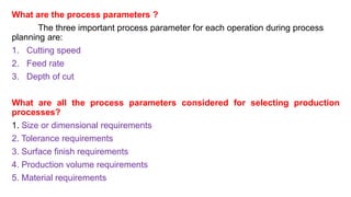
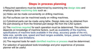
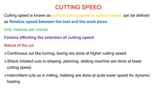
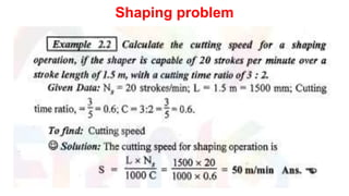
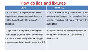
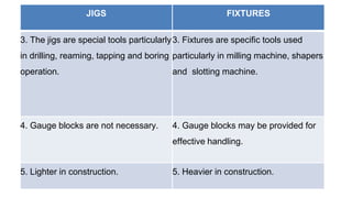
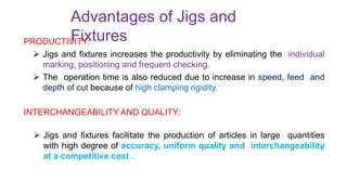
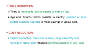
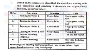
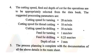
UNIT 2 – PROCESS PLANNING ACTIVITIES
Process parameters calculation for various production processes-Selection jigs and fixtures- Selection of quality assurance methods - Set of documents for process planning-Economics of process planning- case studies
Construction method of steel structure space frame .pptx
PPCE unit 2 (ME8793 – PROCESS PLANNING AND COST ESTIMATION )
1. WELCOME
UNIT 2 – PROCESS PLANNING ACTIVITIES
ME8793 – PROCESS PLANNING AND
COST ESTIMATION (PPCE)
2. UNIT 2 – PROCESS PLANNING
ACTIVITIES
• Process parameters calculation for various production
processes-Selection jigs and fixtures- Selection of quality
assurance methods - Set of documents for process planning-
Economics of process planning- case studies
4. What are the process parameters ?
The three important process parameter for each operation during process
planning are:
1. Cutting speed
2. Feed rate
3. Depth of cut
What are all the process parameters considered for selecting production
processes?
1. Size or dimensional requirements
2. Tolerance requirements
3. Surface finish requirements
4. Production volume requirements
5. Material requirements
5. How to use the materials more economically in production
process?
Better stock utilization through materials control
1. Sale of scrap
2. Re-usable materials
3. Material cost balance sheet
4. Process effects materials cost
What are the most influential factors in terms of tool
performance?
Factors affecting tool performance are:
1. Cutting tool materials
2. Cutting tool geometry
3. Cutting fluids
6. What are the factors affecting speed feed and depth of cut?
1. The workpiece material and geometry;
2. The tool material and geometry;
3. The processing time available as specified by production planning
How to reduce the processing cost?
The cost of processing can be reduced by eliminating unnecessary operations.
This can be achieved in number of ways and are accomplished through proper
planning
1. Changing product design.
2. Changing the operation sequence.
3. Changing the basic process.
4. Combining operations
7. What are the advantages of combining
operations?
1. Improved accuracy
2. Reduced labour cost
3. Reduced plant fixed cost
4. Less tooling required
5. Less handling required
6. Fewer setups
7. Smaller in process inventory
8. Less scrap
What are the limitations of combined
operations?
1. Maintaining tool accuracy
2. Possible higher tool costs
3. Maintaining dimensions for
several baselines
4. Combination tooling subject to
downtime
5. More costly setups
6. More costly scrap
7. Compromises on operational
speed
8. Chip disposal
8. Explain the process planning procedure and List out the information
required for process planning. (16 marks)
(or)
Explain the steps involved in process planning. (8 marks)
9. Steps in process planning
i) Required operations must be determined by examining the design data and
employing basic machining data such as :
(a) Holes can be made conveniently on drilling machines.
(b) Flat surfaces can be machined easily on milling machines.
(c) Cylindrical parts can be made using lathe. Design data can be obtained from
the part-drawing or from the finished part design file from the CAD system.
(ii) The machines required for each operation must be determined. This selection
depends on knowledge of machine factors, such as availability of the machine,
specifications of machine tools available in the shop, accuracy grade of the m/c,
table size, spindle size, speed and feed ranges available, torque, power, machining
rate and other size limitations.
(iii) The required tools for each identified machine or process must be determined.
For selection of specialized tools knowledge and prior experience of process
planner will be useful.
10. • Cont…
(iv) The optimum cutting parameters for each selected tool must be determined.
These parameters include cutting speed, feed rate, depth of cut, and type of
coolant/lubricant to be used. This determination depends on design data, such
as work material, tool material, surface finish specifications and behaviour of
cutting tool. Again expertise knowledge and prior experience of process
planner and methods engineer will be useful in this regard. Machining data
handbooks can also be referred.
(v) Finally an optimum combination of these machining processes must be
determined. The best process plan is the one which minimizes manufacturing
time and cost. This provides a detailed plan for the economical manufacturing
of the part.
(vi) The results of each of these five basic steps can be seen in the final form of the
process plan
11. Explain the factors to be considered in selection of process
parameters (13 marks)
The three Process parameters to be calculated for each operation during
process planning are
Cutting Speed
Feed Rate
Depth of Cut
12. CUTTING SPEED:
Cutting speed is known as surface cutting speed or surface speed, can be defined
as Relative speed between the tool and the work piece
Unit: meteres per minute
Factors affecting the selection of cutting speed
Nature of the cut
Continuous cut like turning, boring are done at higher cutting speed
Shock initiated cuts in shaping, planning, slotting machine are done at lower
cutting speed.
Intermittent cuts as in milling, hobbing are done at quite lower speed for dynamic
loading
13. Work material
Harder and stronger materials are machined at lower cutting
speed
Soft, non-sticky materials can be machined at higher cutting
speed
Cutting tool material
Cutting fluid application
Purpose of machining
Rough machining (lower cutting speed)
Finish machining (higher cutting speed)
Kind of machining operation
Capacity of machine tool
Condition of machine tool
18. FEED AND FEED RATE
Feed is the distance through which the tool advances into the work piece during
one revolution of the workpiece or the cutter.
Feed rate is the speed at which the cutting tool penetrates the work piece
Unit: millimeters per minute
Factors affecting feed rate:
1. Nature of the cut
2. Work material
3. Cutting tool material
4. Cutting fluid application
5. Purpose of machining
6. Kind of machining operation
7. Capacity of machine tool
19. DEPTH OF CUT:
Depth of cut is the thickness of the layer of metal removed in one cut or
pass,
measured in a direction perpendicular to the machined surface
Unit : millimetre
The feed and depth of cut for a particular operation depend on the
material to be machined, surface finish required and tool used.
21. INTRODUCTI
ON
The successful running of any mass production depends upon the
interchangeability to facilitate easy assembly and reduction of unit cost.
Mass production methods demand a fast and easy method of
positioning work for accurate operations on it.
Jigs and fixtures are production tools used to accurately
manufacture duplicate and interchangeable parts.
Jigs and fixtures are specially designed so that large numbers of
components can be machined or assembled identically, and to ensure
interchangeability of components.
22. JIGS
It is a work holding device that holds, supports and locates the workpiece
and guides the cutting tool for a specific operation.
Jigs are usually fitted with hardened steel bushings for guiding or other
cutting tools.
A jig is a type of tool used to control the location and/or motion of another
tool.
A jig's primary purpose is to provide repeatability, accuracy, and
interchangeability in the manufacturing of products.
A device that does both functions (holding the work and guiding a tool) is
called a jig.
An example of a jig is when a key is duplicated, the original is used as a jig
so the new key can have the same path as the old one.
25. FIXTUR
ES
It is a work holding device that holds, supports and locates the
workpiece for a specific operation but does not guide the
cutting tool.
It provides only a reference surface or a device.
What makes a fixture unique is that each one is built to fit a particular
part or shape.
The main purpose of a fixture is to locate and in some cases hold a
workpiece during either a machining operation or some other
industrial process. A jig differs from a fixture in that a it guides the
tool to its correct position in addition to locating and supporting
the workpiece.
Examples: Vises, chucks
30. How do jigs and fixtures
differ
JIGS FIXTURES
1. It is a work holding device that holds,
supports and locates the workpiece and
guides the cutting tool for a specific
operation.
1. It is a work holding device that holds,
supports and locates the workpiece for a
specific operation but does not guide the
cutting tool
2. Jigs are not clamped to the drill press
table unless large diameters to be drilled
and there is a necessity to move the jig to
bring one each bush directly under the drill.
2. Fixtures should be securely clamped to
the table of the machine upon which the
work is done.
31. JIGS FIXTURES
3. The jigs are special tools particularly
in drilling, reaming, tapping and boring
operation.
3. Fixtures are specific tools used
particularly in milling machine, shapers
and slotting machine.
4. Gauge blocks are not necessary. 4. Gauge blocks may be provided for
effective handling.
5. Lighter in construction. 5. Heavier in construction.
32. Advantages of Jigs and
Fixtures
PRODUCTIVITY:
Jigs and fixtures increases the productivity by eliminating the individual
marking, positioning and frequent checking.
The operation time is also reduced due to increase in speed, feed and
depth of cut because of high clamping rigidity.
INTERCHANGEABILITY AND QUALITY:
Jigs and fixtures facilitate the production of articles in large quantities
with high degree of accuracy, uniform quality and interchangeability
at a competitive cost .
33. SKILL REDUCTION:
There is no need for skillful setting of work on tool.
Jigs and fixtures makes possible to employ unskilled or semi
skilled machine operator to make savings in labour cost.
COST REDUCTION:
Higher production, reduction in scrap, easy assembly and
savings in labour cost results in ultimate reduction in unit cost.
34. Fundamental principles of Jigs
and Fixtures design
LOCATING POINTS:
Good facilities should be provided for locating the work.
The article to be machined must be easily inserted and quickly
taken out from the jig so that no time is wasted in placing the
workpiece in position to perform operations.
The position of workpiece should be accurate with respect to
tool guiding in the jig or setting elements in fixture.
FOOL PROOF:
The design of jigs and fixtures should be such that it would not
permit the workpiece or the tool to inserted in any position other
than the correct one.
35. • REDUCTION OF IDLE TIME: Design of Jigs and Fixtures
should be such that the process, loading, clamping and
unloading time of the workpiece takes minimum as far as
possible.
•
• WEIGHT OF JIGS AND FIXTURES: It should be easy to
handle, smaller in size and low cost in regard to amount of
material used without sacrificing rigidity and stiffness.
•
MATERIALS FOR JIGS AND FIXTURES: Usually made of
hardened materials to avoid frequent damage and to resist
wear. Example- MS, Cast iron, Die steel, CS, HSS.
36. •
CLAMPING DEVICE:
It should be as simple as possible without sacrificing
effectiveness. The strength of clamp should be such that
not only to hold the workpiece firmly in place but also to
take the strain of the cutting tool without springing
when designing the jigs and fixtures.
37. Essential features of Jigs and Fixtures
Reduction of idle time –
Should enableeasyclamping and unloading such that idle
time is minimum
Cleanliness of machining process –
Design must be such that not much time is wasted in cleaning of scarfs,
burrs, chips etc.
Provision for coolant –
Provision should be there so that the tool is cooled and the swarfs and
chips are washed away
38. Hardened surfaces – All locating and supporting surfaces should
be hardened materials as far as conditions permit so that they
are not quickly worn out and accuracy is retained for a long time
Inserts and pads – Should always be riveted to those faces of
the clamps which will come in contact with finished surfaces of
the workpiece so that they are not spoilt
Fool-proofing – Pins and other devices of
simple nature incorporated in such a position that they will
always spoil the placement of the component or
hinder the fitting of the cutting tool until the latter are in
correct pos
39. Economic soundness – Equipment should be economically sound,
cost of design and manufacture should be in proportion to the
quantity and price of producer
Easy manipulation – It should be as light in weight as possible and
easy to handle so that workman is not subjected to fatigue, should
be provided with adequate lift aids
Initial location – Should be ensured that workpiece is not located
on more than 3 points in anyone plane test to avoid rocking, spring
loading should be done
Position of clamps – Clamping should occur directly above the
points supporting the workpiece to avoid distortion and springing
40. Clearance – Sufficient amount of clearance should be provided
around the work so that operator’s hands can easily enter the
body for placing the workpiece and any variations of work can be
accommodated
Ejecting devices – Proper ejecting devices should be incorporated
in the body to push the workpiece out after operation
Rigidity and stability – It should remain perfectly rigid and stable
during operation. Provision should be made for proper positioning
and rigidly holding the jigs and fixtures
Safety – The design should assure perfect safety of the operator
41. General rules for
designing
Compare the cost of production of work with
present tools with the expected cost of production,
using the tool to be made and see that the cost of
buildings is not in excess of expected gain.
Decide upon locating points and outline
clamping arrangement
Make all clamping and binding devices as quick
acting as possible
Make the jig fool proof
Make some locating points adjustable
Avoid complicated clamping
arrangements
42. Round all corners
Provide handles wherever these will make handling
easy Provide abundant clearance
Provide holes on escapes for chips
Locate clamps so that they will be in best
position to resist the pressure of the cutting tool
when at work
Place all clamps as nearly as possible opposite
some bearing point of the work to avoid
springing action
Before using in the shop, test all jigs as soon as
made
43. MATERIALS
USED
Jigs and Fixtures are made of variety of materials, some of which can be
hardened to resist wear.
Materials generally used:
High speed Steel: Cutting tools like drills, reamers and milling cutters.
Die steels: Used for press tools, contain 1% carbon, 0.5 to 1% tungsten and
less quantities of silicon and manganese.
Carbon steels: Used for standard cutting tools.
Collet steels: Spring steels containing 1% carbon, 0.5% manganese and
less of silicon.
44. 5. Non shrinking tool
steels:
High carbon or high chromium
Very little distortion during heat
treatment. Used widely for fine,
intricate press tools.
6. Nickel chrome steels: Used for gears.
7. High tensile steels: Used for fasteners like
high tensile screws
8.Mild steel:
Used in most part of Jigs and
Fixtures Cheapest material
45. 9. Cast
Iron: Used for odd shapes to some machining
and laborious fabrication
CI usage requires a pattern for
casting Contains more than 2%
carbon
Has self lubricating properties
Can withstand vibrations and suitable for base
10.Nylon and Fiber: Used for soft lining for
clamps to damage to workpiece due to
clamping pressure
11.Phospher bronze:
used for nuts as have high tensile
strength Used for nuts of the lead
46. Factors to be considered for
design of Jigs and
Fixtures
1. Component-
Design to be studied carefully
Ensure work is performed in a proper sequence
Maximum operations should be performed on a machine in single setting
2. Capacity of the machine-
Careful consideration to be performed on type and capacity of machine.
3. Production requirements-
Design to be made on basis of actual production requirements. Then
comes decision on manual and automatic tooling arrangements.
47. 4.
Location-
•
•
•
•
•
•
•
• Location should ensure equal distribution of
forces throughout all sequence of operation.
Location should be hard resistant, wear resistant
and high degree of accuracy.
Movement of workpiece should be restricted.
Should be fool proofed to avoid improper
locations of the workpiece.
Should facilitate easy and quick loading of
workpiece. Redundant locators should be
avoided.
Sharp corners must be avoided.
At least one datum surface should be establised.
48. 5. Loading and Unloading
arrangements-
There should be adequate clearance for loading
and unloading. Hence process becomes quick
and easy. Size variation must be accepted.
It should be hardened material and non sticky.
6. Clamping arrangements-
Quick acting clamps must be used as far as possible.
The clamping should not cause any deformation
to the workpiece
It should always be arranged directly above points
supporting the work.
Power driven clamps are favoured as they are quick
acting, controllable, reliable and operated without
causing any
fatigue to the operators.
49. Features of clamps:
Clamping pressure should be
low Should not cause
distortion Simple and fool
proof
Movement of clamp should be
minimum Case hardened to prevent
wear Sufficiently robust to avoid
bending
7.Clearance between Jig and Component-
To accommodate various sizes if work
Chips to pass out of the opening between them
8.Ejectors-
To remove work from close fitting locators.
Speeds up unloading of the part from the tool and
hence production rate.
50. 9. Base and Body
construction-
Methods used: Machining, Forging and machining,
Casting, Fabricating, Welding.
10.Tool guiding and cutter setting-
By adjusting the machine or using cutter setting block,
the cutter is set relative to the work in a fixture. The
drill bushes fitted on jig plates guides the tools.
11.Rigidity and vibration-
Must possess enough rigidity and robustness.
Should not vibrate as it may lead to unwanted
movement of
workpiece and tools.
12.Safety-
Operation should be assured full safety.
51. 13. Cost-
Should be simple as possible.
Cost incurred should be
optimum.
14. Materials generally
used-
Sl. No Part Name Material
1 Jig body CI
2 Stud MS
3 Drill/Bush Gun metal
4 Pin MS
5 Nut MS
53. What is Quality?
• Quality is extremely hard to
define, and it is simply
stated:
• "Fit for use or purpose”.
• It is all about meeting the
needs and expectations of
customers with respect to
functionality, design,
reliability, durability, & price
of the product.
What is Quality Assurance?
• Quality assurance (QA) is a way of preventing mistakes and
defects in manufactured products and avoiding problems when
delivering products or services to customers
• Quality Assurance (QA) is defined as an activity to ensure that
an organization is providing the best possible product or service to
customers.
• QA focuses on improving the processes to deliver Quality
Products to the customer.
• An organization has to ensure, that processes are efficient and
effective as per the quality standards defined for software
products.
• Quality Assurance is popularly known as QA Testing
54. Total Quality Management
The way of managing organization to achieve excellence
Total – everything
Quality – degree of excellence
Management – art, act or way of organizing, controlling,
planning, directing to achieve certain goals
55. Improve Quality (Product/Service)
Increase Productivity (less rejects, faster job)
Lower Costs and Higher Profit
Business Growth, Competitive, Jobs, Investment
Effect of Quality Improvement
56. Scope of the TQM activity
TQM
Principles &
Practices
Leadership
Customer
satisfaction
Employee
improvement
Continuous
improvement
Supplier
partnership
Performance
measures
Tools &
Techniques
Quantitative Non-quantitative
SPC ISO 9000
ISO 14000
Acceptance
Sampling
Reliability Benchmarking
Experimental
design
FMEA
QFD
Total
productive
maintenance
Management
tools
Concurrent
engineering
57. TQM Six Basic Concepts
1. Leadership
2. Customer Satisfaction
3. Employee Involvement
4. Continuous Process Improvement
5. Supplier Partnership
6. Performance Measures
(All these present an excellent way to run
a business)
58. Definitions of Strategic Quality
Management (SQM)
According to Juran, ‘SQM is a systematic
approach to setting and achieving quality
objectives throughout the company’.
SQM is at the forefront of a broader system of
quality management.
Detre (2004) gives a new definition ‘as
assembling methods and practices aimed at
mobilizing all actors of organization for
sustainable satisfaction of customer needs
and expectations at the best cost’
59. Core Concepts of SQM
We can identify them as:
Customer focus;
Leadership;
Continuous improvement;
Strategic quality planning;
Design quality, speed and prevention;
People participation and partnership; and
Fact-based management.
60. 7 Tools of Quality
Check Sheet
Histogram
Pareto Chart
Cause & Effect diagram
Control Chart
Scatter Diagram
Flow Chart
61. • Explain the importance of selection of the right
quality assurance method during manufacturing
(13 marks )
62. • All manufacturing organizations have the common goal of making
a profit.
• The basic model of added value previously presented focuses on
the main input of materials undergoing some transformation
process and value being added to that material.
• A profit is made if the value added is greater than the cost to
process the material. However, a profit will only be made if the
customer is satisfied with the product.
• In the globally competitive market, this is where the factor of
product quality is seen to be important.
63. • The transformation processes mentioned above in this instance are obviously
manufacturing processes.
• However, all manufacturing processes have some degree of inherent variability, even
highly automated processes such as CNC milling.
• Therefore, steps must be taken to ensure that the product specification is adhered to
in spite of this variability.
• The starting point for this is the establishment of the capability of theprocesses being
used.
• However, except in the case of the introduction of new processes, the capability of
available processes should be known.
• These data should be documented and available to the process planner if required.
64. • Based on the capability of the process being employed, the process planner
will determine which are the most appropriate quality assurance (QA) tools
and techniques to employ.
• These will range from basic measurement tools such as callipers,
micrometers and gauges to the use of coordinate measuring machines
(CMMs).
• Also covered will be the application of statistical process control (SPC)
methods.
• Although SPC and process capability studies will most probably be designed
and carried out by quality engineering, it is essential that the process planner
has an understanding of these in order to enter into meaningful dialogue with
regards to process capability.
65. In fact, the process planner will have to liaise closely with the
quality function on a number of issues with regards to the process plan.
These include:
• identifying inspection locations;
• identifying appropriate inspection and testing methods;
• the frequency of inspection and testing;
• evaluation of inspection and test data;
• Identifying corrective action where appropriate.
66. • All of the above will influence the processes, equipment, tools and
manufacturing parameters to be used for a given job, particularly
in the case where corrective action involves changing any of
these.
• Therefore, the process planner requires a knowledge and
understanding of all of these aspects of product quality.
67. • What is Inspection? Write briefly about the different
methods of inspections followed in industries.
(16 marks)
68. INSPECTION
Quality related in-process inspection is an essential part of quality
control in manufacturing.
It includes measuring, examining or testing one or more
characteristics of a product or process.
Inspection includes separation of defective parts from the non-
defective parts.
69. The objectives of the Inspection
(i) To sort out confirm and non-conforming product
(ii) To initiate means to determine variations during manufacture
(iii)To provide means to discover inefficiency during manufacture
71. DETERMINATION OF INSPECTION
STAGES
Quality inspection serves three main purposes:
Identification of the problem.
Preventing its occurrence.
Elimination of the problem.
Type of production system.
Type of layout.
Type of machine used.
72. PURPOSE OF INSPECTION
To distinguish good lots from bad lots.
To distinguish good pieces from bad pieces.
To determine if the process is changing.
To rate quality of product.
To rate accuracy of inspectors.
To measure precision of instruments.
To secure products design information.
73. STAGES OF INSPECTION
Inspection of incoming material.
Inspection during the manufacturing process.
Inspection of Production processes.
Inspection of finished goods when it is completely
manufactured.
Inspection of the product before delivery, if material
is stored from long time.
74. Methods of inspection
There are two methods of inspection. They are:
i) 100% inspection, and
ii) Sampling inspection,
75. 100% inspection
• 100% or cent percent inspection is quite common when the number
of parts to be inspection is relatively small.
• Here every part is examined as per the specification or standard
established and acceptance or rejection of the part depend on the
examination.
76. Sampling inspection
• The use of sampling inspection is made when it is not practical or too
costly to inspect each piece.
• A random sample from a batch is inspected and the batch is
accepted if the sample is satisfactory.
• If the sample is not to the desired specification then either entire
batch may be inspected piece by piece or rejected as a whole.
• Statistical methods are employed to determine the portion of total
quality of batch which will serve as reliable sample.
77. Types of inspection
Inspection can be classified according to the type of data
involved as:
1. Inspection of variable, and
2. Inspection of attributes.
• All qualitative characteristics are know as attributes. All
characteristics that can be quantified and measurable are known
as variables.
78. ATTRIBUTES VARIABLES
Number of defective pieces found in a
sample.
Percentage of accurate invoices.
Weekly number of accidents in a
factory.
Number of complaints.
Mistakes per week.
Monthly number of tools rejected.
Errors per thousand lines of code
Percentage of absenteeism.
Dimension of a measured.
Temperature during heat treatment.
Tensile strength of steel bar.
Hours per week correcting documents.
Time to process travel expense
accounts.
Days from order receipt to shipment.
Cost of engineering changes per month.
Time between system crashes.
Cost of rush shipment.
79. Measurement instruments
The selection of appropriate measurement instrument to be
employed is basically depends on the type of quality characteristic of the
component considered.
Measurement: The different types of quality characteristics that are to be
measured are:
(i) Dimensions/size,
(ii) Physical properties,
(iii)Functionality, and
(iv)Appearance.
80. Set of documents required for process planning
(i) Product design and the engineering drawings pertaining to all the
components of the product. (i.e., components drawings, specifications
and a bill of materials that defines how many of each component go
into the product).
(ii) Machining/Machinability Data Handbook (Tables of cutting speeds,
depth of cut, feeds for different processes and for different work
materials).
(iii) Catalogues of various cutting tools and tool inserts.
(iv) Specifications of various machine tools available in the
shop/catalogues of machine tools in the shop (speeds, feeds,
capacity/power rating of motors, spindle size, table sizes etc.).
(v) Sizes of standard materials commercially available in the market.
(vi) Machine Hr. cost of all equipment available in the shop.
81. • Cont…
(vii) Design Data Handbook.
(viii) Charts of Limits, Fits & Tolerances.
(ix) Tables showing tolerances and surface finish obtainable for different
machining processes.
(x) Tables of standard cost.
(xi) Table of allowances (such as Personal Allowance, Fatigue
Allowance etc. in % of standard time followed by the company).
(xii) Process plans of certain standard components such as shafts,
bushings, flanges etc.
(xiii) Handbooks (such as Tool Engineers Handbook, Design Data
Handbook).
82. Write notes on selection of cost for optimal
processes.
(or)
write notes on economics of process planning
(8 marks)
83. • Two different types of processes can be used for the same job.
• The processes can be compared and optimum process selected with the help
of break-even charts.
• Break-even charts: Break-even charts give the production engineer a powerful
tool
• By which feasible alternative processes can be compared and the process
which gives minimum cost can be selected.
• The fixed and variable costs for two alternative processes are plotted on a
graph to a suitable scale as shown in Fig.
84. F1 = Fixed costs for process
(1)
F2 = Fixed costs for process
(2)
V1 = Variable costs for
process (1)
V2 = Variable costs for
process (2)
QE = Break-even quantity at
quantity QA
TE = Total costs of
manufacture at quantity QE
85. • For each process generally the variable cost is a linear function of the
quantity manufactured.
• Therefore, once the fixed costs have been plotted, only one value fort he
variable costs is required at some value QA and the total cost lines can be
drawn.
• Where these lines intersect is known as the break-even point, i.e., the point
where the total cost of manufacture of quantity QE is same for both process
(1) and process (2). The break-even chart tells us to :
• Use process (1) if the quantity to be manufactured below QE
• Use process (2) if the quantity to be manufactured above QE
• The value of QE can be scaled directly from the chart with sufficient
accuracy, although it can also easily be calculated.
86. A component can be produced with equal ease on either a
capstan lathe or on a single spindle cam operated automatic
lathe. Find the break-even quantity QE if the following
information is known. (16 marks)
87.
88.
89. = 30.00 + 150.00 + 8 (4.00 + 10.00 )
= 180.00 + 112.00
= Rs. 292.00
= 0.02 + 0.25 + 0.17
= Rs. 0.44
Variable costs/1000 components = Rs. 440.00.
These costs can now be plotted on a break-even chat (Fig.) to find the value of QE.
QE is scaled from the break-even chart (Fig.) and found to be 385. If the batch size
to be manufactured is equal to or less than 385 use the capstan lathe.
If the batch size to be manufactured is equal to or greater than 385 use the
automatic lathe. The above is the graphical method of determining Break-even
Quantity.
90. Example 2 A small drive shaft is produced using a CNC lathe.
The machine operator's hourly rate is s per hour. The time
taken to machine the drive shaft is 15 min. The order is for
1500 units. Calculate the direct labour cost for producing the
drive shafts.
91. Solution
Hourly rate = s
• Direct labour hours = 1500 x (15/60) h = 375 h
• Direct labour cost = Hourly rate x Direct labour hours
= s X 375
= s
• Direct material is all the material purchased and used in the finished
product, including any scrap/waste incurred. Examples of these are sheet
steel and sub-assemblies for the automobile industry. This can be calculated
by multiplying the material cost per unit by the number of units produced,
that is,
• Direct material cost = Material cost/unit x Number of units produced
92. Example 3 In Example 2, the steel billet used for
manufacturing the drive shaft costs s per unit (the order is for
1500 units) including chuck allowance and scrap. Calculate
the direct material costs.
93. Solution
• Material cost/unit = s
Number of units = 1500
Direct material cost = Material cost/unit X Number of units
= s 1.67 X 1500
= s
TABLE : Examples of indirect costs
Indirect materials Indirect labour Indirect expenses
Lubricating oil Shop floor supervision Factory rent
Maintenance materials Maintenance Factory rates
Plant spares Store men Plant insurance