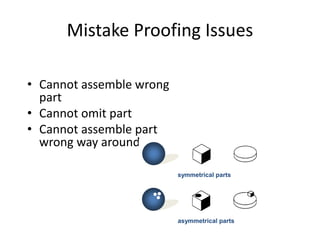
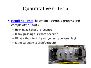
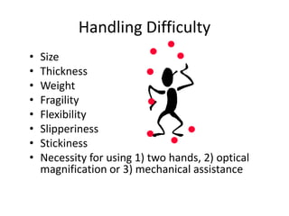
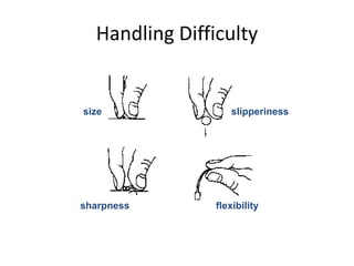
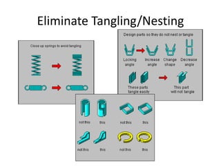
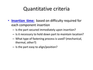
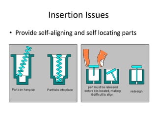
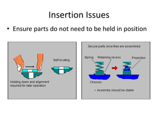
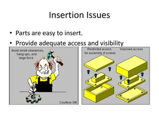
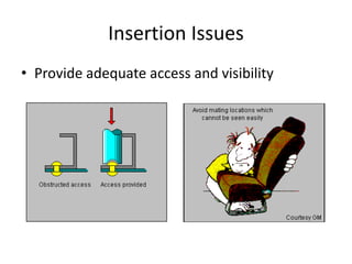
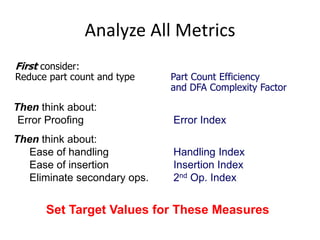
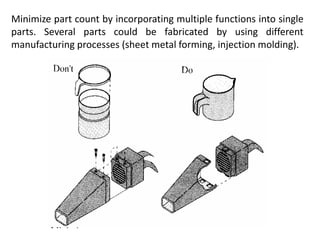
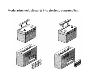
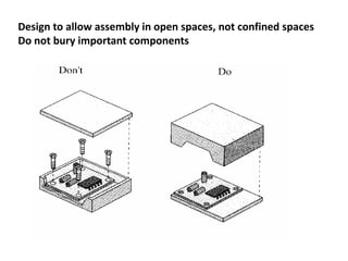
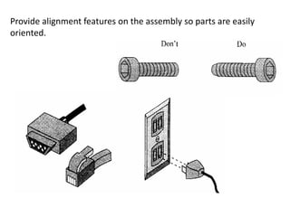
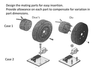
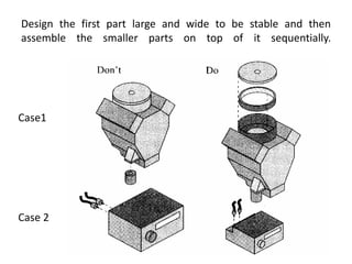
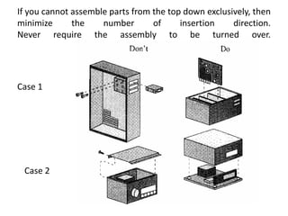
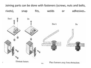
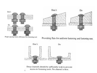
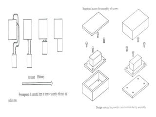
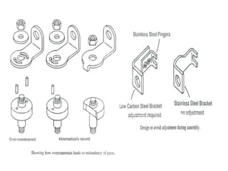
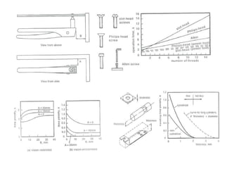
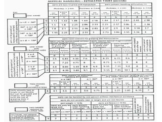
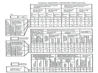
Product design for manual assembly
DFA tool: To reduce manufacturing and assembly costs.
Effectively analyses the ease of assembly, Quick results simple and
easy to use.
Free association of ideas, comparison of alternative designs,
identification of assembly problem areas, evaluation of solutions
logically,
Ideas, reasoning and decisions made during the design process
become useful for future reference.
Database for assembly times and cost factors for various design
situations and production conditions.
The ease of assembly depends on manual or general purpose
automation or special purpose automation.
Manual assembly: Handling, insertion and fastening
Guide lines for part handling:
Design parts with end to end symmetry and rotational
symmetry about the axis of insertion
Provide features that will prevent jamming of parts stacked in
bulk
Avoid features that allow tangling of parts
Guide lines for part insertion and fastening:
Provide chamfers to guide insertion of two mating parts
Generous clearance should be provided
Where ever possible avoid holding down of parts
Use pyramid assembly, progressive
Manual insertion and fastening consist of a finite variety of basic
assembly tasks.
Peg in hole, screw, weld, rivet, press fit.
Factors effecting handling times.
Part symmetry, Part thickness and size, Part weight
Parts requiring two hands: Heavy, Very precise, large, flexible, part
does not posses holding features
Combination of factors
Parts that severely nestle or tangle: Small, vision obscured, high
temp.
Chamfer on insertion operations: peg into a hole, part with a hole
onto peg.
Chamfer on peg is better, curved chamfers are better.
Insertion time depends on length, diameter ,chamfer and clearance.
Avoid jams and disc assembly problems: length and clearance
Holding down time: clearance, grip size and insertion length
Further Design guidelines
Avoid connections
Design so that access for assembly operations is not
restricted.
Avoid adjustments
Use kinematic design principles
Design parts to prevent nesting. Nesting is when parts that are
tacked on top of one another clamp to one another, for example,
cups and coffee lids.
Design parts with orienting features to make alignment easier.
To determine whether it is possible to combine neighboring parts:
•Must the parts move relative to each other?
•Must the parts be electrically or thermally insulated?
•Must the parts be made of different material?
•Does combing the parts interfere with assembly of other parts?
•Will servicing be adversely affected?
If the answer to all questions is “NO”, you should find a way to
combine the parts.
During the assembly of the product, generally a part is required only
when;
1.A kinematic motion of the part is required.
2.A different material is required.
3.Assembly of other parts would otherwise be prevented.
If non of these statements are true, then the parts do not need to
be separate entities and may be combined.
Design for Assembly Principles
• Minimize part count
• Design parts with self-locating features
• Design parts with self-fastening features
• Minimize reorientation of parts during assembly
• Design parts for retrieval, handling, & insertion
• Emphasize ‘Top-Down’ assemblies
• Standardize parts…minimum use of fasteners.
• Encourage modular design
• Design for a base part to locate other components
• Design for component symmetry for insertion
DFA Process
Product Information: functional requirements
Functional analysis
Identify parts that can be standardized
Determine part count efficiencies
Step 2
Step 1
Analyze data for new design
Step 3
Identify handling (grasp & orientation) opportunitiesStep 4
Identify insertion (locate & secure) opportunitiesStep 5
Step 6 Identify opportunities to reduce secondary operations
Identify quality (mistake proofing) opportunities
Benchmark when possible
Determine your practical part count
Step 7
DFA Analysis Worksheet
Product Information: functional requirements
Functional analysis
Identify parts that can be standardized
Determine part count efficiencies
Step One
Considerations/Assumptions
• The first part is essential (base part)
• Non-essential parts:
– Fasteners
– Spacers, washers, O-rings
– Connectors, leads
• Do not include liquids as parts
(e.g.. glue, gasket sealant,)
Part Identification
• List parts in the order
of assembly
• Assign/record part
number
So take it apart!
Count Parts and Interfaces
• List number of parts
(Np)
• List number of
interfaces (Ni)
Determine if Parts Can be Standardized
• Can the current parts
be standardized?:
• Should they be?
• (Only put a “Y” if
both answers are
yes…)
Theoretical Part Count Efficiency
Theoretical Part
Count Efficiency
Theoretical Min. No. Parts
Total Number of Parts
Theoretical Part 1
Count Efficiency 10
Theoretical Part
Count Efficiency
=
= * 100
= 10%
* 100
GoalRule of Thumb – Part
Count Efficiency Goal >
60%
DFA Complexity Factor – Definition
• Assessing complexity of a product design
• Two Factors
• Np – Number of parts
• Ni – Number of part-to-part interfaces
– Multiply the two and take the square root of the
total
– This is known as the DFA Complexity Factor
S Np x S Ni
DFA Complexity Factor – Target
• Smaller is better (Minimize Np and Ni)
• Let Npt = Theoretical Minimum Number of parts
– from the Functional Analysis
– Npt = 5
• Let Nit = Theoretical minimum number of part to part interfaces
– Nit = 2(Npt-1)
– Nit = 2(5-1) = 8
Part 2
Part 3
Part 4
Part 5
Part 1
DCF = S Np x S Ni
DCFt = S Npt x S Nit
DCFt = 5 x 8 = 6.32
Determine Relative Part Cost Levels
• Subjective estimate only
• Low/Medium/High
relative to other parts
in the assembly and/or
product line
Cost Breakdown
• Media paper 21.4%
• Centertube 3.6%
• Endplates (2) 3.0%
• Plastisol 2.6%
• Inner Seal 4.0%
• Spring 0.9%
• Shell 31.4%
• Nutplate 21.0%
• Retainer 4.8%
• Loctite 0.3%
• End Seal 7.0%
Step Two
Determine Practical Minimum Part Count
• Team assessment of
practical changes
• Tradeoffs between part
cost and assembly cost
Implementation
Risk
HighMediumLow
Short
Term
Medium
Term
Long
Term
Idea Classification
Fastener Cost
• Select the
most
inexpensive
fastening
method
required plastic bending
riveting
screwing
snap fit
General Design Principles
Self-fastening features
General Design Principles
Asymmetric Part Symmetry of a part
makes assembly easier
Symmetry eliminates reorientation
Step
Three
Identify quality (mistake proofing) opportunities
Mistake Proofing Issues
• Cannot assemble wrong
part
• Cannot omit part
• Cannot assemble part
wrong way around.
symmetrical parts
asymmetrical parts
Step Four
Identify handling (grasp and orientation) opportunities
Quantitative criteria
• Handling Time: based on assembly process and
complexity of parts
– How many hands are required?
– Is any grasping assistance needed?
– What is the effect of part symmetry on assembly?
– Is the part easy to align/position?
Handling Difficulty
• Size
• Thickness
• Weight
• Fragility
• Flexibility
• Slipperiness
• Stickiness
• Necessity for using 1) two hands, 2) optical
magnification or 3) mechanical assistance
Handling Difficulty
size slipperiness
sharpness flexibility
Eliminate Tangling/Nesting
Step Five
Identify insertion (locate & secure) opportunities
Quantitative criteria
• Insertion time: based on difficulty required for
each component insertion
– Is the part secured immediately upon insertion?
– Is it necessary to hold down part to maintain location?
– What type of fastening process is used? (mechanical,
thermal, other?)
– Is the part easy to align/position?
Insertion Issues
• Provide self-aligning and self locating parts
Insertion Issues
• Ensure parts do not need to be held in position
Insertion Issues
• Parts are easy to insert.
• Provide adequate access and visibility
Insertion Issues
• Provide adequate access and visibility
Step Six
Identify opportunities to reduce secondary operations
Eliminate Secondary Operations
• Re-orientation (assemble in Z axis)
• Screwing, drilling, twisting, riveting, bending,
crimping.
Rivet
Eliminate Secondary Operations
• Welding, soldering, gluing.
• Painting, lubricating, applying liquid or gas.
• Testing, measuring, adjusting.
Error = Sum all Y’s in Error Columns
Proofing Theoretical Min. No. Parts
Handling = Sum all Y’s in Handling Columns
Index Theoretical Min. No. Parts
Insertion = Sum all Y’s in Insertion Columns
Index Theoretical Min. No. Parts
2nd Op. = Sum all Y’s in 2nd Op. Columns
Index Theoretical Min. No. Parts
Assembly Metrics
Analyze All Metrics
First consider:
Reduce part count and type Part Count Efficiency
and DFA Complexity Factor
Then think about:
Error Proofing Error Index
Then think about:
Ease of handling Handling Index
Ease of insertion Insertion Index
Eliminate secondary ops. 2nd Op. Index
Set Target Values for These Measures
Step
Seven
Analyze data for new design
Minimize part count by incorporating multiple functions into single
parts. Several parts could be fabricated by using different
manufacturing processes (sheet metal forming, injection molding).
Modularize multiple parts into single sub-assemblies.
Design to allow assembly in open spaces, not confined spaces
Do not bury important components
Parts should easily indicate orientation for insertion.
Parts should have self-locking features so that the precise alignment
during assembly is not required, or provide marks (indentation) to
make orientation easier.
Standardize parts to reduce variety.
Design parts so they do not tangle or stick to each other.
Distinguish different parts that are shaped similarly, or hard to
distinguish, by non-geometric means, such as color coding
Provide alignment features on the assembly so parts are easily
oriented.
Design the mating parts for easy insertion.
Provide allowance on each part to compensate for variation in
part dimensions.
Case 1
Case 2
Design the first part large and wide to be stable and then
assemble the smaller parts on top of it sequentially.
Case1
Case 2
If you cannot assemble parts from the top down exclusively, then
minimize the number of insertion direction.
Never require the assembly to be turned over.
Case 1
Case 2
Joining parts can be done with fasteners (screws, nuts and bolts,
rivets), snap fits, welds or adhesives.
Dfa guidelines
Dfa guidelines
Dfa guidelines
Dfa guidelines
Dfa guidelines
Dfa guidelines

Dfa guidelines

  • 1.
    Product design formanual assembly DFA tool: To reduce manufacturing and assembly costs. Effectively analyses the ease of assembly, Quick results simple and easy to use. Free association of ideas, comparison of alternative designs, identification of assembly problem areas, evaluation of solutions logically, Ideas, reasoning and decisions made during the design process become useful for future reference. Database for assembly times and cost factors for various design situations and production conditions. The ease of assembly depends on manual or general purpose automation or special purpose automation.
  • 2.
    Manual assembly: Handling,insertion and fastening Guide lines for part handling: Design parts with end to end symmetry and rotational symmetry about the axis of insertion Provide features that will prevent jamming of parts stacked in bulk Avoid features that allow tangling of parts Guide lines for part insertion and fastening: Provide chamfers to guide insertion of two mating parts Generous clearance should be provided Where ever possible avoid holding down of parts Use pyramid assembly, progressive
  • 3.
    Manual insertion andfastening consist of a finite variety of basic assembly tasks. Peg in hole, screw, weld, rivet, press fit. Factors effecting handling times. Part symmetry, Part thickness and size, Part weight Parts requiring two hands: Heavy, Very precise, large, flexible, part does not posses holding features Combination of factors Parts that severely nestle or tangle: Small, vision obscured, high temp. Chamfer on insertion operations: peg into a hole, part with a hole onto peg. Chamfer on peg is better, curved chamfers are better. Insertion time depends on length, diameter ,chamfer and clearance. Avoid jams and disc assembly problems: length and clearance Holding down time: clearance, grip size and insertion length
  • 4.
    Further Design guidelines Avoidconnections Design so that access for assembly operations is not restricted. Avoid adjustments Use kinematic design principles Design parts to prevent nesting. Nesting is when parts that are tacked on top of one another clamp to one another, for example, cups and coffee lids. Design parts with orienting features to make alignment easier.
  • 5.
    To determine whetherit is possible to combine neighboring parts: •Must the parts move relative to each other? •Must the parts be electrically or thermally insulated? •Must the parts be made of different material? •Does combing the parts interfere with assembly of other parts? •Will servicing be adversely affected? If the answer to all questions is “NO”, you should find a way to combine the parts. During the assembly of the product, generally a part is required only when; 1.A kinematic motion of the part is required. 2.A different material is required. 3.Assembly of other parts would otherwise be prevented. If non of these statements are true, then the parts do not need to be separate entities and may be combined.
  • 6.
    Design for AssemblyPrinciples • Minimize part count • Design parts with self-locating features • Design parts with self-fastening features • Minimize reorientation of parts during assembly • Design parts for retrieval, handling, & insertion • Emphasize ‘Top-Down’ assemblies • Standardize parts…minimum use of fasteners. • Encourage modular design • Design for a base part to locate other components • Design for component symmetry for insertion
  • 7.
    DFA Process Product Information:functional requirements Functional analysis Identify parts that can be standardized Determine part count efficiencies Step 2 Step 1 Analyze data for new design Step 3 Identify handling (grasp & orientation) opportunitiesStep 4 Identify insertion (locate & secure) opportunitiesStep 5 Step 6 Identify opportunities to reduce secondary operations Identify quality (mistake proofing) opportunities Benchmark when possible Determine your practical part count Step 7
  • 8.
  • 9.
    Product Information: functionalrequirements Functional analysis Identify parts that can be standardized Determine part count efficiencies Step One
  • 10.
    Considerations/Assumptions • The firstpart is essential (base part) • Non-essential parts: – Fasteners – Spacers, washers, O-rings – Connectors, leads • Do not include liquids as parts (e.g.. glue, gasket sealant,)
  • 11.
    Part Identification • Listparts in the order of assembly • Assign/record part number
  • 12.
    So take itapart!
  • 13.
    Count Parts andInterfaces • List number of parts (Np) • List number of interfaces (Ni)
  • 14.
    Determine if PartsCan be Standardized • Can the current parts be standardized?: • Should they be? • (Only put a “Y” if both answers are yes…)
  • 15.
    Theoretical Part CountEfficiency Theoretical Part Count Efficiency Theoretical Min. No. Parts Total Number of Parts Theoretical Part 1 Count Efficiency 10 Theoretical Part Count Efficiency = = * 100 = 10% * 100 GoalRule of Thumb – Part Count Efficiency Goal > 60%
  • 16.
    DFA Complexity Factor– Definition • Assessing complexity of a product design • Two Factors • Np – Number of parts • Ni – Number of part-to-part interfaces – Multiply the two and take the square root of the total – This is known as the DFA Complexity Factor S Np x S Ni
  • 17.
    DFA Complexity Factor– Target • Smaller is better (Minimize Np and Ni) • Let Npt = Theoretical Minimum Number of parts – from the Functional Analysis – Npt = 5 • Let Nit = Theoretical minimum number of part to part interfaces – Nit = 2(Npt-1) – Nit = 2(5-1) = 8 Part 2 Part 3 Part 4 Part 5 Part 1 DCF = S Np x S Ni DCFt = S Npt x S Nit DCFt = 5 x 8 = 6.32
  • 18.
    Determine Relative PartCost Levels • Subjective estimate only • Low/Medium/High relative to other parts in the assembly and/or product line
  • 19.
    Cost Breakdown • Mediapaper 21.4% • Centertube 3.6% • Endplates (2) 3.0% • Plastisol 2.6% • Inner Seal 4.0% • Spring 0.9% • Shell 31.4% • Nutplate 21.0% • Retainer 4.8% • Loctite 0.3% • End Seal 7.0%
  • 20.
    Step Two Determine PracticalMinimum Part Count
  • 21.
    Determine Practical MinimumPart Count • Team assessment of practical changes • Tradeoffs between part cost and assembly cost
  • 22.
  • 23.
    Fastener Cost • Selectthe most inexpensive fastening method required plastic bending riveting screwing snap fit
  • 24.
  • 25.
    General Design Principles AsymmetricPart Symmetry of a part makes assembly easier Symmetry eliminates reorientation
  • 26.
    Step Three Identify quality (mistakeproofing) opportunities
  • 27.
    Mistake Proofing Issues •Cannot assemble wrong part • Cannot omit part • Cannot assemble part wrong way around. symmetrical parts asymmetrical parts
  • 28.
    Step Four Identify handling(grasp and orientation) opportunities
  • 29.
    Quantitative criteria • HandlingTime: based on assembly process and complexity of parts – How many hands are required? – Is any grasping assistance needed? – What is the effect of part symmetry on assembly? – Is the part easy to align/position?
  • 30.
    Handling Difficulty • Size •Thickness • Weight • Fragility • Flexibility • Slipperiness • Stickiness • Necessity for using 1) two hands, 2) optical magnification or 3) mechanical assistance
  • 31.
  • 32.
  • 33.
    Step Five Identify insertion(locate & secure) opportunities
  • 34.
    Quantitative criteria • Insertiontime: based on difficulty required for each component insertion – Is the part secured immediately upon insertion? – Is it necessary to hold down part to maintain location? – What type of fastening process is used? (mechanical, thermal, other?) – Is the part easy to align/position?
  • 35.
    Insertion Issues • Provideself-aligning and self locating parts
  • 36.
    Insertion Issues • Ensureparts do not need to be held in position
  • 37.
    Insertion Issues • Partsare easy to insert. • Provide adequate access and visibility
  • 38.
    Insertion Issues • Provideadequate access and visibility
  • 39.
    Step Six Identify opportunitiesto reduce secondary operations
  • 40.
    Eliminate Secondary Operations •Re-orientation (assemble in Z axis) • Screwing, drilling, twisting, riveting, bending, crimping. Rivet
  • 41.
    Eliminate Secondary Operations •Welding, soldering, gluing. • Painting, lubricating, applying liquid or gas. • Testing, measuring, adjusting.
  • 42.
    Error = Sumall Y’s in Error Columns Proofing Theoretical Min. No. Parts Handling = Sum all Y’s in Handling Columns Index Theoretical Min. No. Parts Insertion = Sum all Y’s in Insertion Columns Index Theoretical Min. No. Parts 2nd Op. = Sum all Y’s in 2nd Op. Columns Index Theoretical Min. No. Parts Assembly Metrics
  • 43.
    Analyze All Metrics Firstconsider: Reduce part count and type Part Count Efficiency and DFA Complexity Factor Then think about: Error Proofing Error Index Then think about: Ease of handling Handling Index Ease of insertion Insertion Index Eliminate secondary ops. 2nd Op. Index Set Target Values for These Measures
  • 44.
  • 45.
    Minimize part countby incorporating multiple functions into single parts. Several parts could be fabricated by using different manufacturing processes (sheet metal forming, injection molding).
  • 46.
    Modularize multiple partsinto single sub-assemblies.
  • 47.
    Design to allowassembly in open spaces, not confined spaces Do not bury important components
  • 48.
    Parts should easilyindicate orientation for insertion. Parts should have self-locking features so that the precise alignment during assembly is not required, or provide marks (indentation) to make orientation easier.
  • 49.
    Standardize parts toreduce variety.
  • 50.
    Design parts sothey do not tangle or stick to each other.
  • 51.
    Distinguish different partsthat are shaped similarly, or hard to distinguish, by non-geometric means, such as color coding
  • 52.
    Provide alignment featureson the assembly so parts are easily oriented.
  • 53.
    Design the matingparts for easy insertion. Provide allowance on each part to compensate for variation in part dimensions. Case 1 Case 2
  • 54.
    Design the firstpart large and wide to be stable and then assemble the smaller parts on top of it sequentially. Case1 Case 2
  • 55.
    If you cannotassemble parts from the top down exclusively, then minimize the number of insertion direction. Never require the assembly to be turned over. Case 1 Case 2
  • 56.
    Joining parts canbe done with fasteners (screws, nuts and bolts, rivets), snap fits, welds or adhesives.