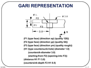
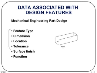
13 - 1
12/12/24
Process Engineering
IE550 -- Manufacturing Systems
Fall 2008
Dr. R. A. Wysk
13 - 2
12/12/24
Chapter 6. PROCESS ENGINEERING
• Process planning is also called: manufacturing planning, process
planning, material processing, process engineering, and machine
routing.
• Which machining processes and parameters are to be used (as well
as those machines capable of performing these processes) to
convert (machine) a piece part from its initial form to a final form
predetermined (usually by a design engineer) from an engineering
drawing.
• The act of preparing detailed work instructions to produce a part.
• How to realize a given product design.
13 - 3
12/12/24
PRODUCT REALIZATION
Product design
Process planning
Operation programming
Verification
Scheduling
Execution
Process,
machine
knowledge
Scheduling
knowledge
13 - 4
12/12/24
PROCESS
PLANNING
Design Machine
Tool
Scheduling and Production Control
Process
Planning
13 - 5
12/12/24
PROBLEMS FACING
MANUFACTURING
INDUSTRY
Fact:
Only 11% of the machine tools in the U.S. are programmable.
More than 53% of the metal-working plants in the U.S. do not have even
one computer-controlled machine.
Some problems:
Cannot justify the cost
Lack of expertise in using such machines
Too small a batch size to offset the planning and programming costs
Source: Kelley, M.R. and Brooks, H., The State of Computerized Automation in US Manufacturing, J.F.
Kennedy School of Government, Harvard University, October 1988.
Potential benefits in reducing turnaround time by using
programmable machine tools have not been realized due to time,
complexity and costs of planning and programming.
13 - 6
12/12/24
DOMAI
N
One-of-a-kind and Small batch
Objectives: Lead-time, Cost
Approaches: process selection, use
existing facilities.
Mass production
Objective: Cost
Approaches: process design, optimization,
materials selection, facilities
design
13 - 7
12/12/24
How do we process engineer?
• How can we make it?
• How much does it cost?
• How long will it take us to complete it?
• How reliable will it be?
• How can we recycle it
13 - 8
12/12/24
How can we make it?
• Is this like something else that we’ve done?
– Yes; What methods were used?
– No; Design a new process
13 - 9
12/12/24
What methods were used?
• Machining methods
• Pressworking
• Welding/fabrication
• Casting
• Powder materials
• Layered deposition
• Others
13 - 10
12/12/24
Welding/fabrication:
Additive techniques
Initial
Stock
Weld
Add-on
Weld
Add-on
Final Product
13 - 11
12/12/24
Machining Methods:
Subtractive techniques
Initial
Stock
Slotting Drilling
Final Product
13 - 12
12/12/24
Casting:
Form Methods
13 - 13
12/12/24
ENGINEERING DESIGN
MODELING
10"+0.01
-0.01
1'-4" +0.01
-0.01
4" +0.01
-0.01
7" +0.05
-0.05
5"+0.01
-0.01
3"+0.01
-0.01
2"+0.01
-0.01 0.001 A B
A
B
S.F. 64 u inch
U*
- *
CSG MODEL
Fa c e
Lo o p
Ed g e
V e rt e x
B-REP MODEL
13 - 14
12/12/24
INTERACTION OF
PLANNING
FUNCTIONS
GEOMETRIC REASONING
PROCESS SELECTION
CUTTER SELECTION
MACHINE TOOL SELECTION
SETUP PLANNING
FIXTURE PLANNING
CUTTER PATH GENERATION
• global & local geometry
• process capability
• process cost
• available tools
• tool dimension and geometry
• geometric constraints
• machine availability, cost
• machine capability
• feature relationship
• approach directions
• process constraints
• fixture constraints
• fixture element function
• locating, supporting, and
clamping surfaces
• stability
• feature merging and split
• path optimization
• obstacle and interference
avoidance
13 - 15
12/12/24
PROCESS
PLAN
• Also called : operation sheet, route sheet, operation planning
summary, or another similar name.
• The detailed plan contains:
route
processes
process parameters
machine and tool selections
fixtures
• How detail the plan is depends on the application.
• Operation: a process
• Operation Plan (Op-plan): contains the description of an operation,
includes tools, machines to be used, process parameters,
machining time, etc.
• Op-plan sequence: Summary of a process plan.
13 - 16
12/12/24
EXAMPLE PROCESS
PLANS
Route Sheet
Part No. S1243
Part Name: Mounting Bracket
1. Mtl Rm
2. Mill02 5
3. Drl01 4
4. Insp 1
workstation Time(min)
by: T.C. Chang
PROCESS PLAN ACE Inc.
Part No. S0125-F
Part Name: Housing
Original: S.D. Smart Date: 1/1/89
Checked: C.S. Good Date: 2/1/89
Material: steel 4340Si
Changes: Date:
Approved: T.C. Chang Date: 2/14/89
No. Operation
Description
Workstation Setup Tool Time
(Min)
10 Mill bottom surface1 MILL01 see attach#1
for illustration
Face mill
6 teeth/4" dia
3 setup
5 machining
20 Mill top surface MILL01 see attach#1 Face mill
6 teeth/4" dia
2 setup
6 machining
30 Drill 4 holes DRL02 set on surface1 twist drill
1/2" dia
2" long
2 setup
3 machining
Detailed Process Plan
Oper. Routing Summary
13 - 17
12/12/24
FACTORS AFFECTING
PROCESS
PLAN SELECTION
• Shape
• Tolerance
• Surface finish
• Size
• Material type
• Quantity
• Value of the product
• Urgency
• Manufacturing system itself
• etc.
13 - 18
12/12/24
PROCESS PLANNING CLASSIFICATION
MANUAL
COMPUTER-AIDED
VARIANT
GT based
Computer aids for editing
Parameters selection
GENERATIVE
Some kind of decision logic
Decision tree/table
Artificial Intelligence
Objective-Oriented
Still experience based
AUTOMATIC
Design understanding
Geometric reasoning capability
13 - 19
12/12/24
REQUIREMENTS IN
MANUAL PROCESS
PLANNING
• ability to interpret an engineering drawing.
• familiar with manufacturing processes and
practice.
• familiar with tooling and fixtures.
• know what resources are available in the shop.
• know how to use reference books, such as
machinability data handbook.
• able to do computations on machining time and
cost.
• familiar with the raw materials.
• know the relative costs of processes, tooling, and
raw materials.
13 - 20
12/12/24
INDUSTRIAL SOLUTION
10" +0.01
-0.01
1'-4" +0.01
-0.01
4" +0.01
-0.01
7" +0.05
-0.05
5" +0.01
-0.01
3" +0.01
-0.01
2" +0.01
-0.01 0.001 A B
A
B
S.F. 64 u inch
PRODUCT
CONCEPT
CAD
CAM
CUTTER
PATH
HUMAN - decision making
COMPUTER - geometric computation, data handling
N0010 G70 G 90 T08 M06
N0020 G00 X2.125 Y-0.475 Z4.000 S3157
N0030 G01 Z1.500 F63 M03
N0040 G01 Y4.100
N0050 G01 X2.625
N0060 G01 Y1.375
N0070 G01 X3.000
N0080 G03 Y2.625 I3.000 J2.000
N0090 G01 Y2.000
N0100 G01 X2.625
N0110 G01 Y-0.100
N0120 G00 Z4.000 T02 M05
N0130 F9.16 S509 M06
N0140 G81 X0.750 Y1.000 Z-0.1 R2.100 M03
N0150 G81 X0.750 Y3.000 Z-0.1 R2.100
N0160 G00 X-1.000 Y-1.000 M30
.
13 - 21
12/12/24
PROCESS PLANNING
STEPS
• Study the overall shape of the part. Use this
information to classify the part and determine the type
of workstation needed.
• Thoroughly study the drawing. Try to identify every
manufacturing features and notes.
• If raw stock is not given, determine the best raw
material shape to use.
• Identify datum surfaces. Use information on datum
surfaces to determine the setups.
• Select machines for each setup.
• For each setup determine the rough sequence of
operations necessary to create all the features.
13 - 22
12/12/24
PROCESS PLANNING
STEPS
(continue)
• Sequence the operations determined in the
previous step.
• Select tools for each operation. Try to use the same
tool for several operations if it is possible. Keep in
mind the trade off on tool change time and
estimated machining time.
• Select or design fixtures for each setup.
• Evaluate the plan generate thus far and make
necessary modifications.
• Select cutting parameters for each operation.
• Prepare the final process plan document.
13 - 23
12/12/24
COMPUTER-AIDED
PROCESS
PLANNING
ADVANTAGES
1. It can reduce the skill required of a planner.
2. It can reduce the process planning time.
3. It can reduce both process planning and
manufacturing cost.
4. It can create more consistent plans.
5. It can produce more accurate plans.
6. It can increase productivity.
13 - 24
12/12/24
WHY AUTOMATED
PROCESS
PLANNING
• Shortening the lead-time
• Manufacturability feedback
• Lowering the production cost
• Consistent process plans
13 - 25
12/12/24
PROCESS
PLANNING
Machining features
Design
Workpiece Selection
Process Selection
Tool Selection
Feed, Speed Selection
Operation Sequencing
Setup Planning
Fixturing Planning
Part Programming
13 - 26
12/12/24
VARIANT PROCESS
PLANNING
Standard
process
plans &
individual
process
plans
process
plan
editing
part
coding
part
family
formation
standard
plan
preparation
part
coding
part
family
search
process
plan
retrieval
finished
process
plan
GROUP TECHNOLOGY BASED RETRIEVAL SYSTEM
13 - 27
12/12/24
PROBLEMS ASSOCIATED WITH
THE VARIANT APPROACH
1. The components to be planned are limited to
similar components previously planned.
2. Experienced process planners are still
required to modify the standard plan for the
specific component.
3. Details of the plan cannot be generated.
4. Variant planning cannot be used in an
entirely automated manufacturing system,
without additional process planning.
13 - 28
12/12/24
ADVANTAGES OF THE
VARIANT APPROACH
1. Once a standard plan has been written, a variety
of components can be planned.
2. Comparatively simple programming and
installation (compared with generative systems)
is required to implement a planning system.
3. The system is understandable, and the planner
has control of the final plan.
4. It is easy to learn, and easy to use.
13 - 29
12/12/24
GENERATIVE APPROACH
A system which automatically synthesizes a
process plan for a new component.
(i) part description
(ii) manufacturing databases
(iii) decision making logic and
algorithms
MAJOR COMPONENTS:
13 - 30
12/12/24
ADVANTAGES OF THE
GENERATIVE APPROACH
1. Generate consistent process plans rapidly;
2. New components can be planned as easily as
existing components;
3. It has potential for integrating with an
automated manufacturing facility to provide
detailed control information.
13 - 31
12/12/24
KEY DEVELOPMENTS
1. The logic of process planning must be
identified and captured.
2. The part to be produced must be clearly and
precisely defined in a computer-compatible
format
3. The captured logic of process planning and the
part description
13 - 32
12/12/24
PRODUCT REPRESENTATION
Geometrical information
Part shape
Design features
Technological information
Tolerances
Surface quality (surface finish, surface integrity)
Special manufacturing notes
Etc.
"Feature information"
Manufacturing features
e.g. slots, holes, pockets, etc.
13 - 33
12/12/24
INPUT REPRESENTATION SELECTION
• How much information is needed?
• Data format required.
• Ease of use for the planning.
• Interface with other functions, such as, part
programming, design, etc.
• Easy recognition of manufacturing features.
• Easy extraction of planning information from the
representation.
13 - 34
12/12/24
WHAT INPUT REPRESENTATIONS
GT CODE
Line drawing
Special language
Symbolic representation
Solid model
CSG
B-Rep
others?
Feature based model
13 - 35
12/12/24
SPECIAL LANGUAGE
10 CYLINDER/3,1/
11 DFIT/K,5/
12 CHAMFER/.2,2.6/
20 CYLINDER/2.5,1.2/
21 LTOL/+0.001,-0.001/
3
1
1.2
2.5
.2x2.6
K5
+.001
-.001
AUTAP
13 - 36
12/12/24
CIMS/PRO REPRESENTATION
a1
a2 a3
a4
a5
a6
t
X
Y Z
sweep
direction
13 - 37
12/12/24
GARI REPRESENTATION
0 3.0
2
.5
0 1.
X
Y
3.0
F1
F2
F3
(F1 (type face) (direction xp) (quality 120))
(F2 (type face) (direction yp) (quality 64))
(F3 (type face) (direction ym) (quality rough))
(H1 (type countersunk-hole) (diameter 1.0)
(countersik-diameter 3.0)
(starting-from F2) (opening-into F3))
(distance H1 F1 3.0)
(countersink-depth F2 H1 0.5)
13 - 38
12/12/24
CONCEPT OF FEATURE
Manufacturing is "feature" based.
Feature:
1 a: the structure, form, or appearance esp. of a
person
b: obs: physical beauty.
2 a: the makeup or appearance of the face or its
parts
b: a part of the face: LINEAMENT
3: a prominent part or characteristic
4: a special attraction
Webster's Ninth New Collegiate Dictionary
13 - 39
12/12/24
FEATURES IN DESIGN AND
MANUFACTURING
A high level geometry which includes a set of
connected geometries. Its meaning is
dependent upon the application domain.
Boss
Pocket with an island
Design Feature vs Manufacturing Feature
13 - 40
12/12/24
DESIGN
FEATURES
• For creating a shape
• For providing a function
Motion Slot feature
13 - 41
12/12/24
MANUFACTURING FEATURES
• For process selection
• For fixturing
End mill a slot
Drilling Round hole
Turning Rotational feature
End milling Plane
surface,
Hole, profile, slot
pocket
Ball end mill Free form
surface
Boring Cylindrical shell
Reaming Cylindrical shell
... ...
Manufacturing
is feature based.
13 - 42
12/12/24
MANUFACTURING FEATURES
(cont.)
?
13 - 43
12/12/24
DATA ASSOCIATED WITH
DESIGN FEATURES
Mechanical Engineering Part Design
• Feature Type
• Dimension
• Location
• Tolerance
• Surface finish
• Function
A Slot
13 - 44
12/12/24
DATA ASSOCIATED WITH
MANUFACTURING FEATURES
• Feature type
• Dimension
• Location
• Tolerance
• Surface finish
• Relations with other features
• Approach directions
Approach
Approach
° Feature classifications are not the same.
13 - 45
12/12/24
FEATURE RECOGNITION
Extract and decompose features from a geometric
model.
• Syntactic pattern recognition
• State transition diagram and automata
• Decomposition
• Logic
• Graph matching
• Face growing
13 - 46
12/12/24
DIFFICULTIES OF FEATURE
RECOGNITION
• Potentially large number of features.
• Features are domain and user specific.
• Lack of a theory in features.
• Input geometric model specific. Based on
incomplete models.
• Computational complexity of the algorithms.
• Existing algorithms are limited to simple
features.
13 - 47
12/12/24
DESIGN WITH MANUFACTURING
FEATURES
Make the design process a simulation of the
manufacturing process. Features are tool swept
volumes and operators are manufacturing
processes.
Design
Process Planning
Bar stock - Profile - Bore hole
Turn profile Drill hole
Bore hole
13 - 48
12/12/24
PROS AND CONS OF DESIGN
WITH
MANUFACTURING FEATURES
• Concurrent engineering - designers are forced
to think about manufacturing process.
• Simplify (eliminate) process planning.
• Hinder the creative thinking of designers.
• Use the wrong talent (designer doing process
planning).
• Interaction of features affects processes.
Pros
Cons
13 - 49
12/12/24
BACKWARD PLANNING
.
Bo rin g
D r i l l i n g
Mi l l i n g
Fin is h e d
p a rt
Wo rkp ie c e
P
l
a
n
n
i
n
g
M
a
c
h
i
n
i
n
g
o
p
e
r
a
t
i
o
n
13 - 50
12/12/24
PROCESS KNOWLEDGE
REPRESENTATION
• Predicate logic
• Production rules
• Semantic Nets
• Frames
• Object Oriented Programming
13 - 51
12/12/24
SOME RESEARCH
ISSUES
• Part design representation: information contents,
data format
• Geometric reasoning: feature recognition, feature
extraction, tool approach directions, feature
relations
• Process selection: backward planning, tolerance
analysis, geometric capability, process knowledge,
process mechanics
• Tool selection: size, length, cut length, shank length,
holder, materials, geometry, roughing, and finishing
tools
13 - 52
12/12/24
SOME RESEARCH
ISSUES
(continue)
• Fixture design: fixture element model, fixturing
knowledge modeling, stability analysis,
friction/cutting force
• Tool path planning: algorithms for features,
gauging and interference avoidance algorithms,
automated path generation
• Software engineering issues: data structure, data
base, knowledge base, planning algorithms, user
interface, software interface
13 - 53
12/12/24
A FEATURE BASED DESIGN/
PROCESS PLANNING
SYSTEM
Geometric Reasoning
Application-Specific Features (e.g. manufacturing features)
blind slot, through slot, step, etc.
approach direction, feed direction
feature relations: precedence and intersection type
Manufacturing-Oriented Design Features
hole, straight slot, T-slot, circular slot, pocket
counterbore, sculptured surface cavity
Principle:
Provide designer with the freedom to describe shape -
avoid constraining manufacturing planning
or requiring detailed manufacturing knowledge.
13 - 54
12/12/24
SOME AUTOMATED PROCESS PLANNING
EFFORTS
U. Mass, Dixon: Features-based design for
manufacturing analysis of extrusions,
castings, injection molding
ASU, Shah: Theory of features study for
CAM-I; Feature-mapping shell
Stanford,Cutkosky: feature-based design,
process planning, fixturing systems.
Helsinki, Mantyla: systems for design &
process planning.
IBM, Rossignac:Editing & validation of
feature models; MAMOUR system.
SDRC, Chung, GE, Simmons: Feature-based
design and casting analysis.
NIST : Automated process planning
CAM-I, UTRC: XPS-2, generative process
planning
U of Maryland, Nau: Semi-generative process
planning
GE R & D, Hines: Art to Part
Penn State, Wysk (Texas A&M): graph based
process planning
Stanford, Cutkosky: FirstCut, integrated design
and manufacturing system based on
features.
CMI & CMU: IMW, feature based design,
expert operation planning.
U. of Twente, Holland, Kals: PARTS , feature
based input, feature recognition, operation
planning.
Allied Bendix, Hummel & Brooks: XCUT
system for cavity operation planning.
IPK Berlin & IPK Aachen
UMIST, B.J. Davies
U. of Leeds, de Pennington
U. of Tokyo, Kimura
Features in Process Planning
Feature in Design
QTC is one of the only efforts that
considers design through inspection
and the only one that uses deep
geometric reasoning to link design
and process planning.
13 - 55
12/12/24
SOME
APPROACHES
CAD
CAM
2-D
Drafting
Process Planner
• automatic drawing interpretation
• gen. type plan generation
Automatic part
programming
3-D
Solid Model
canned/auto. cutter
path cycle
Feature based
solid model
automatic part
programming
• feature refinement
• limited geometric reasoning
• generative planning
• seq may dictated by design
2-D
Drafting
• drawing interpretation
• variant type plan generation
• interactive part programming
NC control
3-D CAD
Model
• interactive drawing interpretation
• gen./variant type plan
generation
canned cutter
path cycles
• geometric reasoning
• expert planner
• no human decision
13 - 56
12/12/24
THE DEVELOPMENT OF CAPP
1960 1970 1980 1990 2000
Intelligence of
the system
Human
Expert
?
manual
planning
Data
base
GT
variant
system
expert
system
geometric
reasoning
elementary
machine
learning
? technology

CIM notes : process engineering concepts in detail

  • 1.
    13 - 1 12/12/24 ProcessEngineering IE550 -- Manufacturing Systems Fall 2008 Dr. R. A. Wysk
  • 2.
    13 - 2 12/12/24 Chapter6. PROCESS ENGINEERING • Process planning is also called: manufacturing planning, process planning, material processing, process engineering, and machine routing. • Which machining processes and parameters are to be used (as well as those machines capable of performing these processes) to convert (machine) a piece part from its initial form to a final form predetermined (usually by a design engineer) from an engineering drawing. • The act of preparing detailed work instructions to produce a part. • How to realize a given product design.
  • 3.
    13 - 3 12/12/24 PRODUCTREALIZATION Product design Process planning Operation programming Verification Scheduling Execution Process, machine knowledge Scheduling knowledge
  • 4.
    13 - 4 12/12/24 PROCESS PLANNING DesignMachine Tool Scheduling and Production Control Process Planning
  • 5.
    13 - 5 12/12/24 PROBLEMSFACING MANUFACTURING INDUSTRY Fact: Only 11% of the machine tools in the U.S. are programmable. More than 53% of the metal-working plants in the U.S. do not have even one computer-controlled machine. Some problems: Cannot justify the cost Lack of expertise in using such machines Too small a batch size to offset the planning and programming costs Source: Kelley, M.R. and Brooks, H., The State of Computerized Automation in US Manufacturing, J.F. Kennedy School of Government, Harvard University, October 1988. Potential benefits in reducing turnaround time by using programmable machine tools have not been realized due to time, complexity and costs of planning and programming.
  • 6.
    13 - 6 12/12/24 DOMAI N One-of-a-kindand Small batch Objectives: Lead-time, Cost Approaches: process selection, use existing facilities. Mass production Objective: Cost Approaches: process design, optimization, materials selection, facilities design
  • 7.
    13 - 7 12/12/24 Howdo we process engineer? • How can we make it? • How much does it cost? • How long will it take us to complete it? • How reliable will it be? • How can we recycle it
  • 8.
    13 - 8 12/12/24 Howcan we make it? • Is this like something else that we’ve done? – Yes; What methods were used? – No; Design a new process
  • 9.
    13 - 9 12/12/24 Whatmethods were used? • Machining methods • Pressworking • Welding/fabrication • Casting • Powder materials • Layered deposition • Others
  • 10.
    13 - 10 12/12/24 Welding/fabrication: Additivetechniques Initial Stock Weld Add-on Weld Add-on Final Product
  • 11.
    13 - 11 12/12/24 MachiningMethods: Subtractive techniques Initial Stock Slotting Drilling Final Product
  • 12.
  • 13.
    13 - 13 12/12/24 ENGINEERINGDESIGN MODELING 10"+0.01 -0.01 1'-4" +0.01 -0.01 4" +0.01 -0.01 7" +0.05 -0.05 5"+0.01 -0.01 3"+0.01 -0.01 2"+0.01 -0.01 0.001 A B A B S.F. 64 u inch U* - * CSG MODEL Fa c e Lo o p Ed g e V e rt e x B-REP MODEL
  • 14.
    13 - 14 12/12/24 INTERACTIONOF PLANNING FUNCTIONS GEOMETRIC REASONING PROCESS SELECTION CUTTER SELECTION MACHINE TOOL SELECTION SETUP PLANNING FIXTURE PLANNING CUTTER PATH GENERATION • global & local geometry • process capability • process cost • available tools • tool dimension and geometry • geometric constraints • machine availability, cost • machine capability • feature relationship • approach directions • process constraints • fixture constraints • fixture element function • locating, supporting, and clamping surfaces • stability • feature merging and split • path optimization • obstacle and interference avoidance
  • 15.
    13 - 15 12/12/24 PROCESS PLAN •Also called : operation sheet, route sheet, operation planning summary, or another similar name. • The detailed plan contains: route processes process parameters machine and tool selections fixtures • How detail the plan is depends on the application. • Operation: a process • Operation Plan (Op-plan): contains the description of an operation, includes tools, machines to be used, process parameters, machining time, etc. • Op-plan sequence: Summary of a process plan.
  • 16.
    13 - 16 12/12/24 EXAMPLEPROCESS PLANS Route Sheet Part No. S1243 Part Name: Mounting Bracket 1. Mtl Rm 2. Mill02 5 3. Drl01 4 4. Insp 1 workstation Time(min) by: T.C. Chang PROCESS PLAN ACE Inc. Part No. S0125-F Part Name: Housing Original: S.D. Smart Date: 1/1/89 Checked: C.S. Good Date: 2/1/89 Material: steel 4340Si Changes: Date: Approved: T.C. Chang Date: 2/14/89 No. Operation Description Workstation Setup Tool Time (Min) 10 Mill bottom surface1 MILL01 see attach#1 for illustration Face mill 6 teeth/4" dia 3 setup 5 machining 20 Mill top surface MILL01 see attach#1 Face mill 6 teeth/4" dia 2 setup 6 machining 30 Drill 4 holes DRL02 set on surface1 twist drill 1/2" dia 2" long 2 setup 3 machining Detailed Process Plan Oper. Routing Summary
  • 17.
    13 - 17 12/12/24 FACTORSAFFECTING PROCESS PLAN SELECTION • Shape • Tolerance • Surface finish • Size • Material type • Quantity • Value of the product • Urgency • Manufacturing system itself • etc.
  • 18.
    13 - 18 12/12/24 PROCESSPLANNING CLASSIFICATION MANUAL COMPUTER-AIDED VARIANT GT based Computer aids for editing Parameters selection GENERATIVE Some kind of decision logic Decision tree/table Artificial Intelligence Objective-Oriented Still experience based AUTOMATIC Design understanding Geometric reasoning capability
  • 19.
    13 - 19 12/12/24 REQUIREMENTSIN MANUAL PROCESS PLANNING • ability to interpret an engineering drawing. • familiar with manufacturing processes and practice. • familiar with tooling and fixtures. • know what resources are available in the shop. • know how to use reference books, such as machinability data handbook. • able to do computations on machining time and cost. • familiar with the raw materials. • know the relative costs of processes, tooling, and raw materials.
  • 20.
    13 - 20 12/12/24 INDUSTRIALSOLUTION 10" +0.01 -0.01 1'-4" +0.01 -0.01 4" +0.01 -0.01 7" +0.05 -0.05 5" +0.01 -0.01 3" +0.01 -0.01 2" +0.01 -0.01 0.001 A B A B S.F. 64 u inch PRODUCT CONCEPT CAD CAM CUTTER PATH HUMAN - decision making COMPUTER - geometric computation, data handling N0010 G70 G 90 T08 M06 N0020 G00 X2.125 Y-0.475 Z4.000 S3157 N0030 G01 Z1.500 F63 M03 N0040 G01 Y4.100 N0050 G01 X2.625 N0060 G01 Y1.375 N0070 G01 X3.000 N0080 G03 Y2.625 I3.000 J2.000 N0090 G01 Y2.000 N0100 G01 X2.625 N0110 G01 Y-0.100 N0120 G00 Z4.000 T02 M05 N0130 F9.16 S509 M06 N0140 G81 X0.750 Y1.000 Z-0.1 R2.100 M03 N0150 G81 X0.750 Y3.000 Z-0.1 R2.100 N0160 G00 X-1.000 Y-1.000 M30 .
  • 21.
    13 - 21 12/12/24 PROCESSPLANNING STEPS • Study the overall shape of the part. Use this information to classify the part and determine the type of workstation needed. • Thoroughly study the drawing. Try to identify every manufacturing features and notes. • If raw stock is not given, determine the best raw material shape to use. • Identify datum surfaces. Use information on datum surfaces to determine the setups. • Select machines for each setup. • For each setup determine the rough sequence of operations necessary to create all the features.
  • 22.
    13 - 22 12/12/24 PROCESSPLANNING STEPS (continue) • Sequence the operations determined in the previous step. • Select tools for each operation. Try to use the same tool for several operations if it is possible. Keep in mind the trade off on tool change time and estimated machining time. • Select or design fixtures for each setup. • Evaluate the plan generate thus far and make necessary modifications. • Select cutting parameters for each operation. • Prepare the final process plan document.
  • 23.
    13 - 23 12/12/24 COMPUTER-AIDED PROCESS PLANNING ADVANTAGES 1.It can reduce the skill required of a planner. 2. It can reduce the process planning time. 3. It can reduce both process planning and manufacturing cost. 4. It can create more consistent plans. 5. It can produce more accurate plans. 6. It can increase productivity.
  • 24.
    13 - 24 12/12/24 WHYAUTOMATED PROCESS PLANNING • Shortening the lead-time • Manufacturability feedback • Lowering the production cost • Consistent process plans
  • 25.
    13 - 25 12/12/24 PROCESS PLANNING Machiningfeatures Design Workpiece Selection Process Selection Tool Selection Feed, Speed Selection Operation Sequencing Setup Planning Fixturing Planning Part Programming
  • 26.
    13 - 26 12/12/24 VARIANTPROCESS PLANNING Standard process plans & individual process plans process plan editing part coding part family formation standard plan preparation part coding part family search process plan retrieval finished process plan GROUP TECHNOLOGY BASED RETRIEVAL SYSTEM
  • 27.
    13 - 27 12/12/24 PROBLEMSASSOCIATED WITH THE VARIANT APPROACH 1. The components to be planned are limited to similar components previously planned. 2. Experienced process planners are still required to modify the standard plan for the specific component. 3. Details of the plan cannot be generated. 4. Variant planning cannot be used in an entirely automated manufacturing system, without additional process planning.
  • 28.
    13 - 28 12/12/24 ADVANTAGESOF THE VARIANT APPROACH 1. Once a standard plan has been written, a variety of components can be planned. 2. Comparatively simple programming and installation (compared with generative systems) is required to implement a planning system. 3. The system is understandable, and the planner has control of the final plan. 4. It is easy to learn, and easy to use.
  • 29.
    13 - 29 12/12/24 GENERATIVEAPPROACH A system which automatically synthesizes a process plan for a new component. (i) part description (ii) manufacturing databases (iii) decision making logic and algorithms MAJOR COMPONENTS:
  • 30.
    13 - 30 12/12/24 ADVANTAGESOF THE GENERATIVE APPROACH 1. Generate consistent process plans rapidly; 2. New components can be planned as easily as existing components; 3. It has potential for integrating with an automated manufacturing facility to provide detailed control information.
  • 31.
    13 - 31 12/12/24 KEYDEVELOPMENTS 1. The logic of process planning must be identified and captured. 2. The part to be produced must be clearly and precisely defined in a computer-compatible format 3. The captured logic of process planning and the part description
  • 32.
    13 - 32 12/12/24 PRODUCTREPRESENTATION Geometrical information Part shape Design features Technological information Tolerances Surface quality (surface finish, surface integrity) Special manufacturing notes Etc. "Feature information" Manufacturing features e.g. slots, holes, pockets, etc.
  • 33.
    13 - 33 12/12/24 INPUTREPRESENTATION SELECTION • How much information is needed? • Data format required. • Ease of use for the planning. • Interface with other functions, such as, part programming, design, etc. • Easy recognition of manufacturing features. • Easy extraction of planning information from the representation.
  • 34.
    13 - 34 12/12/24 WHATINPUT REPRESENTATIONS GT CODE Line drawing Special language Symbolic representation Solid model CSG B-Rep others? Feature based model
  • 35.
    13 - 35 12/12/24 SPECIALLANGUAGE 10 CYLINDER/3,1/ 11 DFIT/K,5/ 12 CHAMFER/.2,2.6/ 20 CYLINDER/2.5,1.2/ 21 LTOL/+0.001,-0.001/ 3 1 1.2 2.5 .2x2.6 K5 +.001 -.001 AUTAP
  • 36.
    13 - 36 12/12/24 CIMS/PROREPRESENTATION a1 a2 a3 a4 a5 a6 t X Y Z sweep direction
  • 37.
    13 - 37 12/12/24 GARIREPRESENTATION 0 3.0 2 .5 0 1. X Y 3.0 F1 F2 F3 (F1 (type face) (direction xp) (quality 120)) (F2 (type face) (direction yp) (quality 64)) (F3 (type face) (direction ym) (quality rough)) (H1 (type countersunk-hole) (diameter 1.0) (countersik-diameter 3.0) (starting-from F2) (opening-into F3)) (distance H1 F1 3.0) (countersink-depth F2 H1 0.5)
  • 38.
    13 - 38 12/12/24 CONCEPTOF FEATURE Manufacturing is "feature" based. Feature: 1 a: the structure, form, or appearance esp. of a person b: obs: physical beauty. 2 a: the makeup or appearance of the face or its parts b: a part of the face: LINEAMENT 3: a prominent part or characteristic 4: a special attraction Webster's Ninth New Collegiate Dictionary
  • 39.
    13 - 39 12/12/24 FEATURESIN DESIGN AND MANUFACTURING A high level geometry which includes a set of connected geometries. Its meaning is dependent upon the application domain. Boss Pocket with an island Design Feature vs Manufacturing Feature
  • 40.
    13 - 40 12/12/24 DESIGN FEATURES •For creating a shape • For providing a function Motion Slot feature
  • 41.
    13 - 41 12/12/24 MANUFACTURINGFEATURES • For process selection • For fixturing End mill a slot Drilling Round hole Turning Rotational feature End milling Plane surface, Hole, profile, slot pocket Ball end mill Free form surface Boring Cylindrical shell Reaming Cylindrical shell ... ... Manufacturing is feature based.
  • 42.
  • 43.
    13 - 43 12/12/24 DATAASSOCIATED WITH DESIGN FEATURES Mechanical Engineering Part Design • Feature Type • Dimension • Location • Tolerance • Surface finish • Function A Slot
  • 44.
    13 - 44 12/12/24 DATAASSOCIATED WITH MANUFACTURING FEATURES • Feature type • Dimension • Location • Tolerance • Surface finish • Relations with other features • Approach directions Approach Approach ° Feature classifications are not the same.
  • 45.
    13 - 45 12/12/24 FEATURERECOGNITION Extract and decompose features from a geometric model. • Syntactic pattern recognition • State transition diagram and automata • Decomposition • Logic • Graph matching • Face growing
  • 46.
    13 - 46 12/12/24 DIFFICULTIESOF FEATURE RECOGNITION • Potentially large number of features. • Features are domain and user specific. • Lack of a theory in features. • Input geometric model specific. Based on incomplete models. • Computational complexity of the algorithms. • Existing algorithms are limited to simple features.
  • 47.
    13 - 47 12/12/24 DESIGNWITH MANUFACTURING FEATURES Make the design process a simulation of the manufacturing process. Features are tool swept volumes and operators are manufacturing processes. Design Process Planning Bar stock - Profile - Bore hole Turn profile Drill hole Bore hole
  • 48.
    13 - 48 12/12/24 PROSAND CONS OF DESIGN WITH MANUFACTURING FEATURES • Concurrent engineering - designers are forced to think about manufacturing process. • Simplify (eliminate) process planning. • Hinder the creative thinking of designers. • Use the wrong talent (designer doing process planning). • Interaction of features affects processes. Pros Cons
  • 49.
    13 - 49 12/12/24 BACKWARDPLANNING . Bo rin g D r i l l i n g Mi l l i n g Fin is h e d p a rt Wo rkp ie c e P l a n n i n g M a c h i n i n g o p e r a t i o n
  • 50.
    13 - 50 12/12/24 PROCESSKNOWLEDGE REPRESENTATION • Predicate logic • Production rules • Semantic Nets • Frames • Object Oriented Programming
  • 51.
    13 - 51 12/12/24 SOMERESEARCH ISSUES • Part design representation: information contents, data format • Geometric reasoning: feature recognition, feature extraction, tool approach directions, feature relations • Process selection: backward planning, tolerance analysis, geometric capability, process knowledge, process mechanics • Tool selection: size, length, cut length, shank length, holder, materials, geometry, roughing, and finishing tools
  • 52.
    13 - 52 12/12/24 SOMERESEARCH ISSUES (continue) • Fixture design: fixture element model, fixturing knowledge modeling, stability analysis, friction/cutting force • Tool path planning: algorithms for features, gauging and interference avoidance algorithms, automated path generation • Software engineering issues: data structure, data base, knowledge base, planning algorithms, user interface, software interface
  • 53.
    13 - 53 12/12/24 AFEATURE BASED DESIGN/ PROCESS PLANNING SYSTEM Geometric Reasoning Application-Specific Features (e.g. manufacturing features) blind slot, through slot, step, etc. approach direction, feed direction feature relations: precedence and intersection type Manufacturing-Oriented Design Features hole, straight slot, T-slot, circular slot, pocket counterbore, sculptured surface cavity Principle: Provide designer with the freedom to describe shape - avoid constraining manufacturing planning or requiring detailed manufacturing knowledge.
  • 54.
    13 - 54 12/12/24 SOMEAUTOMATED PROCESS PLANNING EFFORTS U. Mass, Dixon: Features-based design for manufacturing analysis of extrusions, castings, injection molding ASU, Shah: Theory of features study for CAM-I; Feature-mapping shell Stanford,Cutkosky: feature-based design, process planning, fixturing systems. Helsinki, Mantyla: systems for design & process planning. IBM, Rossignac:Editing & validation of feature models; MAMOUR system. SDRC, Chung, GE, Simmons: Feature-based design and casting analysis. NIST : Automated process planning CAM-I, UTRC: XPS-2, generative process planning U of Maryland, Nau: Semi-generative process planning GE R & D, Hines: Art to Part Penn State, Wysk (Texas A&M): graph based process planning Stanford, Cutkosky: FirstCut, integrated design and manufacturing system based on features. CMI & CMU: IMW, feature based design, expert operation planning. U. of Twente, Holland, Kals: PARTS , feature based input, feature recognition, operation planning. Allied Bendix, Hummel & Brooks: XCUT system for cavity operation planning. IPK Berlin & IPK Aachen UMIST, B.J. Davies U. of Leeds, de Pennington U. of Tokyo, Kimura Features in Process Planning Feature in Design QTC is one of the only efforts that considers design through inspection and the only one that uses deep geometric reasoning to link design and process planning.
  • 55.
    13 - 55 12/12/24 SOME APPROACHES CAD CAM 2-D Drafting ProcessPlanner • automatic drawing interpretation • gen. type plan generation Automatic part programming 3-D Solid Model canned/auto. cutter path cycle Feature based solid model automatic part programming • feature refinement • limited geometric reasoning • generative planning • seq may dictated by design 2-D Drafting • drawing interpretation • variant type plan generation • interactive part programming NC control 3-D CAD Model • interactive drawing interpretation • gen./variant type plan generation canned cutter path cycles • geometric reasoning • expert planner • no human decision
  • 56.
    13 - 56 12/12/24 THEDEVELOPMENT OF CAPP 1960 1970 1980 1990 2000 Intelligence of the system Human Expert ? manual planning Data base GT variant system expert system geometric reasoning elementary machine learning ? technology