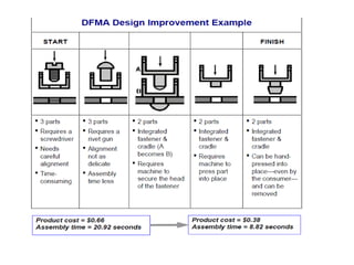
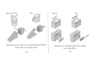
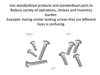
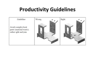
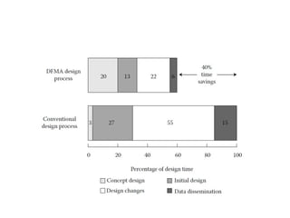
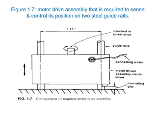
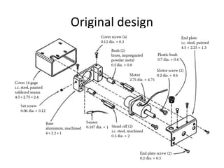
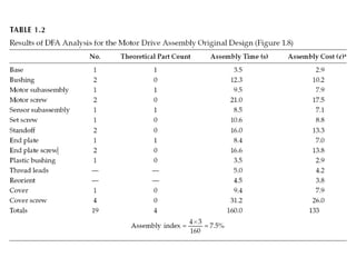
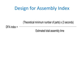
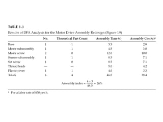
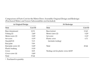
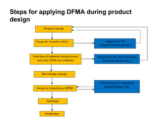
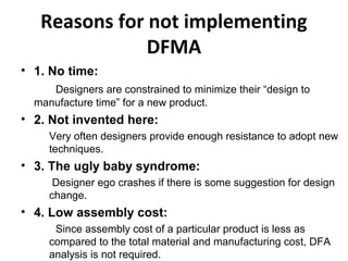
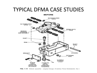
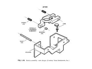
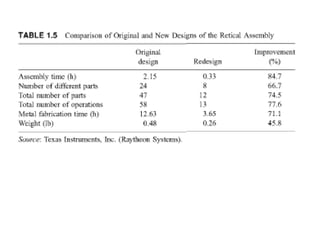
15MEX02 - DESIGN FOR
MANUFACTURING
TOPICS
• UNIT I : FUNDAMENTALS
• UNIT II : DESIGN FOR MANUAL ASSEMBLY
• UNIT III : DESIGN FOR CASTING AND FORMING
• UNIT IV : DESIGN FOR MACHINING
• UNIT V : DESIGN FOR THE ENVIRONMENT
UNIT I : FUNDAMENTALS
• Design for Manufacture and Assembly
• Implementation issues
• Typical DFMA case studies
• Selection of materials and processes
• General requirements for early materials and process
selection
• Selection of manufacturing processes
• Process capabilities
• Selection of materials primary process/material
selection
• Systematic selection of processes and material
• “to manufacture” refers to the manufacturing
of the individual component parts of a
product or assembly
• “to assemble” refers to the addition or joining
of parts to form the completed product.
What Is Design for Manufacture and
Assembly?
• Design for manufacture (DFM) means the
design for the ease of manufacture of the
collection of parts that form the product after
assembly
• Design for assembly (DFA) means the design
of the product for the ease of assembly.
Differences
• Design for Assembly (DFA) :
concerned only with reducing product
assembly cost – minimizes number of assembly
operations – individual parts tend to be more
complex in design
• Design for Manufacturing (DFM) :
concerned with reducing overall part
production cost – minimizes complexity of
manufacturing operations
DFMA: Design for manufacture and
assembly is a combination of DFA and DFM
Three main activities of DFMA
• As the basis for concurrent engineering studies to
provide guidance to the design team in
simplifying the product structure to reduce
manufacturing and assembly costs, and to
quantify the improvements.
• As a benchmarking tool to study competitors
products and quantify manufacturing and
assembly difficulties.
• As a should-cost tool to help control costs and to
help negotiate suppliers contracts.
Design for Assembly Principles
Minimize part count
Design parts with self-locating features
Design parts with self-fastening features
Minimize reorientation of parts during assembly
 Design parts for retrieval, handling, & insertion
 Emphasize ‘Top-Down’ assemblies
 Standardize parts…minimum use of fasteners.
Encourage modular design
 Design for a base part to locate other components
 Design for component symmetry for insertion
• DFM and DFA Design Guidelines
Minimize part count by incorporating multiple
functions into single parts
Several parts could be fabricated by using
different manufacturing Processes (sheet metal
forming, injection molding).
Ask yourself if a part function can be preformed
by a neighboring part
Use standardized products and standardized parts to
Reduce variety of operations, choices and inventory
burden
Example: having similar looking screws that are different
Sizes is confusing.
Productivity Guidelines
How Does DFMA Work?
“Over-the-wall” design, historically the way of doing business.
Traditionally, the attitude of designers are:
• “we design it, you build it.” This has now been termed
the “over-the-wall approach” where the designer sits on
one side of the wall and throws designs over the wall to
the manufacturing engineers, who then have to deal
with the various manufacturing problems arising
because they were not involved in the design effort.
• The resulting teamwork avoids many problems.
However, these teams, now called simultaneous
engineering or concurrent engineering teams, require
analysis tools to help them study proposed designs and
evaluate them from the point of view of manufacturing
difficulty and cost.
Figure 1.7: motor drive assembly that is required to sense
& control its position on two steel guide rails.
• Motor must be fully enclosed for set of
principle/concepts
• Have a removable cover to provide access to
adjustment of the position sensor.
• Principal requirements:
– A rigid base designed to slide up and down with
guide rails that will both support the motor and
locate the sensor.
– The motor and sensor have wires connecting to a
power supply and control unit.
Original design
DFA provides three criteria against which each part must
be examined:
1.During operation of the product, does the part move
relative to all other parts already assembled?
2.Must the part be of a different material than or be
isolated from all other parts already assembled? Only
fundamental reasons concerned with material properties
are acceptable.
3.Must the part be separate from all other parts already
assembled because otherwise necessary assembly or
disassembly of other separate parts would be impossible.
1.Base: 1st
part to be assembled, it is a theoretically necessary part.
2.Bushings (2): Base and bushings could be of same material.
3.Motor: standard subassembly of parts.
4.Motor screws (2): separate fasteners do not meet the criteria
because an integral fastening arrangement is always theoretically
possible.
5.Sensor: Standard subassembly.
6.Set screw: Theoretically not necessary.
7.Standoffs (2): They could be incorporated into the base.
8.End plate: Must be separate for reasons of assembly of necessary
items.
9.End plate screws (2): Theoretically not necessary.
10.Plastic bushing: Could be of the same material as the end plate.
11.Cover: Could be combined with the end plate.
12.Cover screws (4): Theoretically not necessary.
Design for Assembly Index
DFA index =
(Theoretical minimum number of parts) x (3 seconds)
Estimated total assembly time
Re design
• Motor and sensor subassemblies could be arranged to snap
or screw into the base and a plastic cover designed to snap
on.
• Only four separate items would be needed instead of 19.
• These four items represent the theoretical min number
needed to satisfy the requirements of the product design
without considering practical limitations.
• Two screws are needed to secure the motor.
• One set screw is needed to hold the sensor.
• The design of these screws could be improved by providing
them with pilot points to facilitate assembly.
• The two powder metal bushings are unnecessary.
• It is difficult to justify the separate standoffs, end plate, cover,
plastic bushing, and six screws.
Steps for applying DFMA during product
design
Reasons for not implementing
DFMA
• 1. No time:
Designers are constrained to minimize their “design to
manufacture time” for a new product.
• 2. Not invented here:
Very often designers provide enough resistance to adopt new
techniques.
• 3. The ugly baby syndrome:
Designer ego crashes if there is some suggestion for design
change.
• 4. Low assembly cost:
Since assembly cost of a particular product is less as
compared to the total material and manufacturing cost, DFA
analysis is not required.
• 5. Low volume:
Often it is expressed that DFMA is applicable for
large quantity production.
• 6.Database doesn't apply to our product:
Since DFMA is applied at the early stages of
design before the detail design has taken place;
there is a need for a generalized database.
• 7. We have been doing it for years:
Sometimes industry uses the design for
producibility concept to fine-tune the design. There
is a misconception that they are doing the similar
practice of DFMA.
• 8. It is only value analysis:
The objective of DFMA and value analysis are
same, however DFMA is used at the early stages of
design and can be used in every stages of design.
• 9. DFMA is only one among many techniques.
• 10. DFMA leads to products that are more difficult
to service.
• 11. Prefer design rules:
Sometimes design rules guide the designer in the
wrong direction.
• 12. Refuse to use DFMA:
Individual doesn't have the incentive to
adopt the new technology and use the tools
available.
• Advantages of applying DFMA during product design
are as follows:
• • DFMA not only reduces the manufacturing cost of
the product but it helps to reduce the time to market
and quality of the product.
• • DFMA provides a systematic procedure for analyzing
a proposed design from the point of view of assembly
and manufacture.
• • Any reduction in the number of parts reduces the
cost as well as the inventory.
• • DFMA tools encouraged the dialogue between the
designer and manufacturing engineer during the early
stages of design.
TYPICAL DFMA CASE STUDIES
dfma  unit-1
dfma  unit-1

dfma unit-1

  • 1.
    15MEX02 - DESIGNFOR MANUFACTURING
  • 2.
    TOPICS • UNIT I: FUNDAMENTALS • UNIT II : DESIGN FOR MANUAL ASSEMBLY • UNIT III : DESIGN FOR CASTING AND FORMING • UNIT IV : DESIGN FOR MACHINING • UNIT V : DESIGN FOR THE ENVIRONMENT
  • 3.
    UNIT I :FUNDAMENTALS • Design for Manufacture and Assembly • Implementation issues • Typical DFMA case studies • Selection of materials and processes • General requirements for early materials and process selection • Selection of manufacturing processes • Process capabilities • Selection of materials primary process/material selection • Systematic selection of processes and material
  • 4.
    • “to manufacture”refers to the manufacturing of the individual component parts of a product or assembly • “to assemble” refers to the addition or joining of parts to form the completed product. What Is Design for Manufacture and Assembly?
  • 5.
    • Design formanufacture (DFM) means the design for the ease of manufacture of the collection of parts that form the product after assembly • Design for assembly (DFA) means the design of the product for the ease of assembly.
  • 6.
    Differences • Design forAssembly (DFA) : concerned only with reducing product assembly cost – minimizes number of assembly operations – individual parts tend to be more complex in design • Design for Manufacturing (DFM) : concerned with reducing overall part production cost – minimizes complexity of manufacturing operations
  • 7.
    DFMA: Design formanufacture and assembly is a combination of DFA and DFM
  • 8.
    Three main activitiesof DFMA • As the basis for concurrent engineering studies to provide guidance to the design team in simplifying the product structure to reduce manufacturing and assembly costs, and to quantify the improvements. • As a benchmarking tool to study competitors products and quantify manufacturing and assembly difficulties. • As a should-cost tool to help control costs and to help negotiate suppliers contracts.
  • 9.
    Design for AssemblyPrinciples Minimize part count Design parts with self-locating features Design parts with self-fastening features Minimize reorientation of parts during assembly  Design parts for retrieval, handling, & insertion  Emphasize ‘Top-Down’ assemblies  Standardize parts…minimum use of fasteners. Encourage modular design  Design for a base part to locate other components  Design for component symmetry for insertion
  • 11.
    • DFM andDFA Design Guidelines Minimize part count by incorporating multiple functions into single parts Several parts could be fabricated by using different manufacturing Processes (sheet metal forming, injection molding). Ask yourself if a part function can be preformed by a neighboring part
  • 13.
    Use standardized productsand standardized parts to Reduce variety of operations, choices and inventory burden Example: having similar looking screws that are different Sizes is confusing.
  • 14.
  • 17.
    How Does DFMAWork? “Over-the-wall” design, historically the way of doing business.
  • 18.
    Traditionally, the attitudeof designers are: • “we design it, you build it.” This has now been termed the “over-the-wall approach” where the designer sits on one side of the wall and throws designs over the wall to the manufacturing engineers, who then have to deal with the various manufacturing problems arising because they were not involved in the design effort. • The resulting teamwork avoids many problems. However, these teams, now called simultaneous engineering or concurrent engineering teams, require analysis tools to help them study proposed designs and evaluate them from the point of view of manufacturing difficulty and cost.
  • 19.
    Figure 1.7: motordrive assembly that is required to sense & control its position on two steel guide rails.
  • 20.
    • Motor mustbe fully enclosed for set of principle/concepts • Have a removable cover to provide access to adjustment of the position sensor. • Principal requirements: – A rigid base designed to slide up and down with guide rails that will both support the motor and locate the sensor. – The motor and sensor have wires connecting to a power supply and control unit.
  • 21.
  • 22.
    DFA provides threecriteria against which each part must be examined: 1.During operation of the product, does the part move relative to all other parts already assembled? 2.Must the part be of a different material than or be isolated from all other parts already assembled? Only fundamental reasons concerned with material properties are acceptable. 3.Must the part be separate from all other parts already assembled because otherwise necessary assembly or disassembly of other separate parts would be impossible.
  • 23.
    1.Base: 1st part tobe assembled, it is a theoretically necessary part. 2.Bushings (2): Base and bushings could be of same material. 3.Motor: standard subassembly of parts. 4.Motor screws (2): separate fasteners do not meet the criteria because an integral fastening arrangement is always theoretically possible. 5.Sensor: Standard subassembly. 6.Set screw: Theoretically not necessary. 7.Standoffs (2): They could be incorporated into the base. 8.End plate: Must be separate for reasons of assembly of necessary items. 9.End plate screws (2): Theoretically not necessary. 10.Plastic bushing: Could be of the same material as the end plate. 11.Cover: Could be combined with the end plate. 12.Cover screws (4): Theoretically not necessary.
  • 25.
    Design for AssemblyIndex DFA index = (Theoretical minimum number of parts) x (3 seconds) Estimated total assembly time
  • 26.
  • 27.
    • Motor andsensor subassemblies could be arranged to snap or screw into the base and a plastic cover designed to snap on. • Only four separate items would be needed instead of 19. • These four items represent the theoretical min number needed to satisfy the requirements of the product design without considering practical limitations. • Two screws are needed to secure the motor. • One set screw is needed to hold the sensor. • The design of these screws could be improved by providing them with pilot points to facilitate assembly. • The two powder metal bushings are unnecessary. • It is difficult to justify the separate standoffs, end plate, cover, plastic bushing, and six screws.
  • 30.
    Steps for applyingDFMA during product design
  • 31.
    Reasons for notimplementing DFMA • 1. No time: Designers are constrained to minimize their “design to manufacture time” for a new product. • 2. Not invented here: Very often designers provide enough resistance to adopt new techniques. • 3. The ugly baby syndrome: Designer ego crashes if there is some suggestion for design change. • 4. Low assembly cost: Since assembly cost of a particular product is less as compared to the total material and manufacturing cost, DFA analysis is not required.
  • 32.
    • 5. Lowvolume: Often it is expressed that DFMA is applicable for large quantity production. • 6.Database doesn't apply to our product: Since DFMA is applied at the early stages of design before the detail design has taken place; there is a need for a generalized database. • 7. We have been doing it for years: Sometimes industry uses the design for producibility concept to fine-tune the design. There is a misconception that they are doing the similar practice of DFMA.
  • 33.
    • 8. Itis only value analysis: The objective of DFMA and value analysis are same, however DFMA is used at the early stages of design and can be used in every stages of design. • 9. DFMA is only one among many techniques. • 10. DFMA leads to products that are more difficult to service. • 11. Prefer design rules: Sometimes design rules guide the designer in the wrong direction.
  • 34.
    • 12. Refuseto use DFMA: Individual doesn't have the incentive to adopt the new technology and use the tools available.
  • 35.
    • Advantages ofapplying DFMA during product design are as follows: • • DFMA not only reduces the manufacturing cost of the product but it helps to reduce the time to market and quality of the product. • • DFMA provides a systematic procedure for analyzing a proposed design from the point of view of assembly and manufacture. • • Any reduction in the number of parts reduces the cost as well as the inventory. • • DFMA tools encouraged the dialogue between the designer and manufacturing engineer during the early stages of design.
  • 36.