Download to read offline
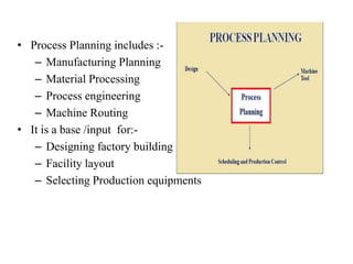
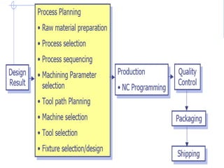
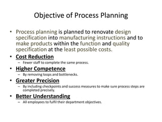
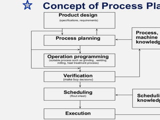
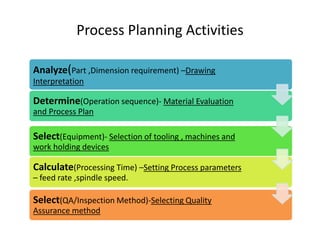
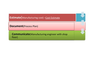
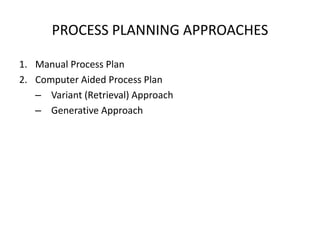
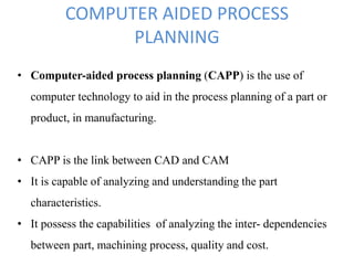
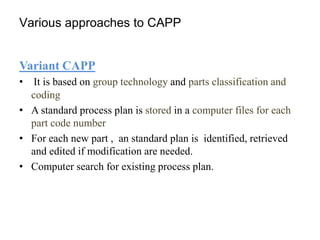
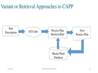


This document summarizes computer aided process planning. It discusses that process planning converts design information into manufacturing instructions to effectively produce products. It then describes different approaches to computer aided process planning including manual process planning, variant approach using group technology and part coding, and generative approach. The variant approach retrieves standard plans while the generative approach automatically generates new plans by matching part geometry to manufacturing capabilities. Overall, computer aided process planning aims to reduce time, labor, costs and improve precision and understanding of manufacturing processes.


![[Deck] What's New in Spark-Iceberg Integration via DSV2.pptx](https://cdn.slidesharecdn.com/ss_thumbnails/deckwhatsnewinspark-icebergintegrationviadsv2-260210005337-25955b12-thumbnail.jpg?width=640&height=640&fit=bounds)


