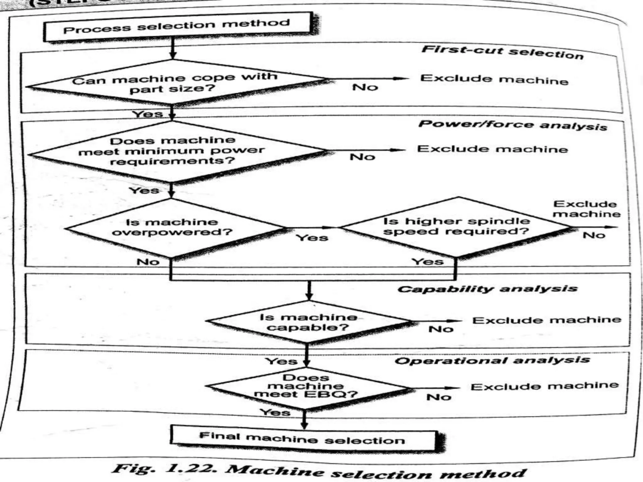
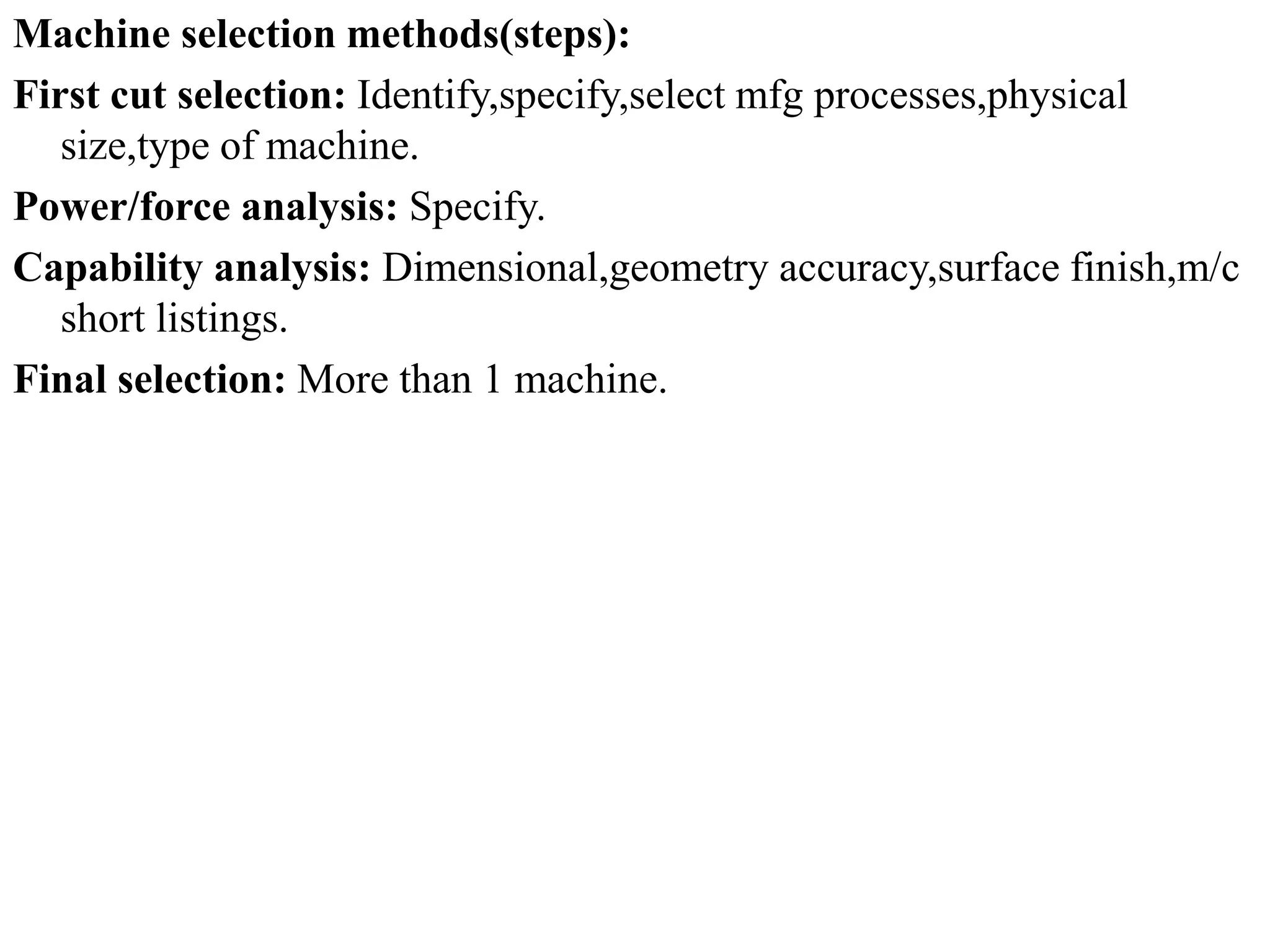
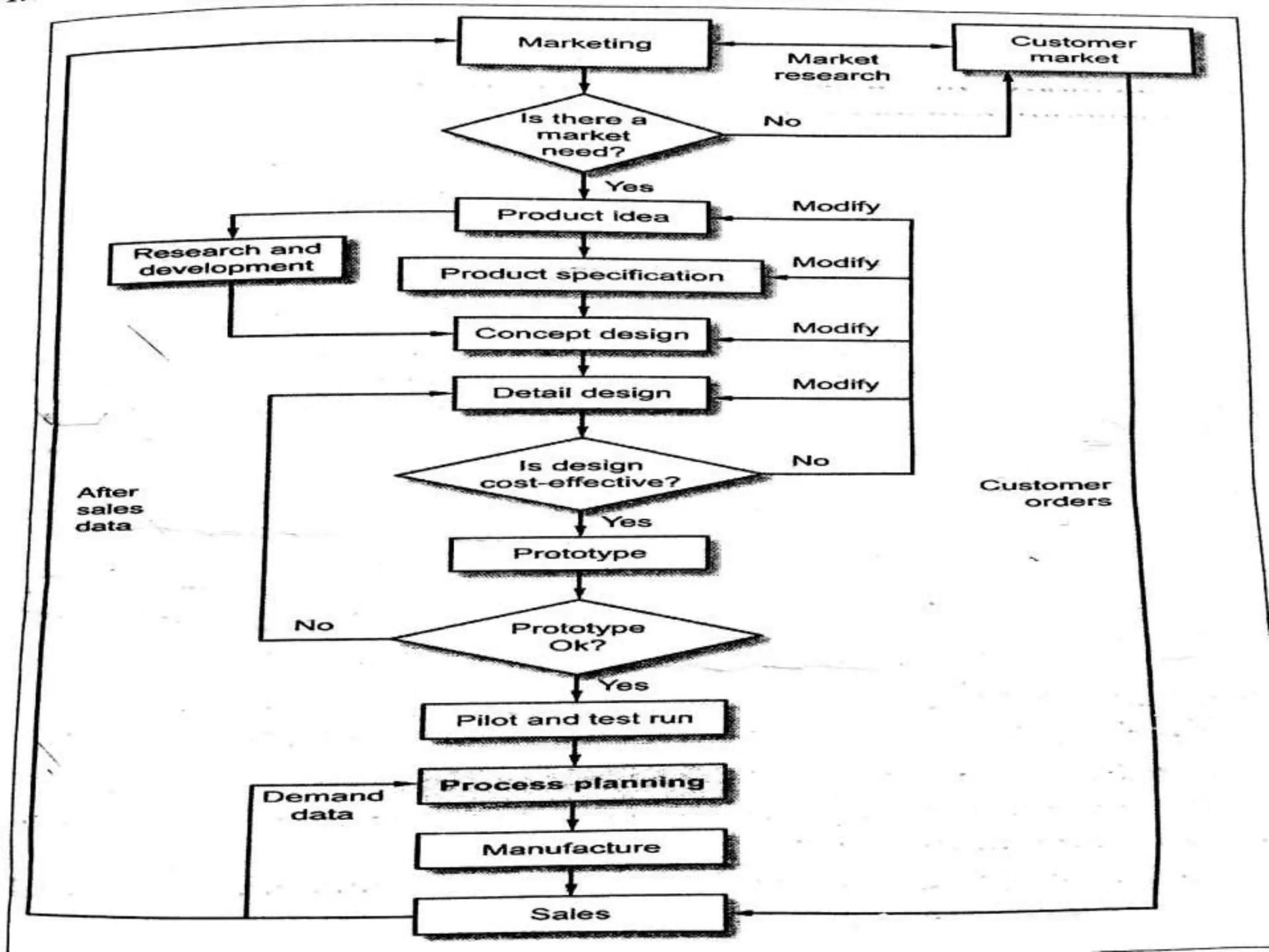
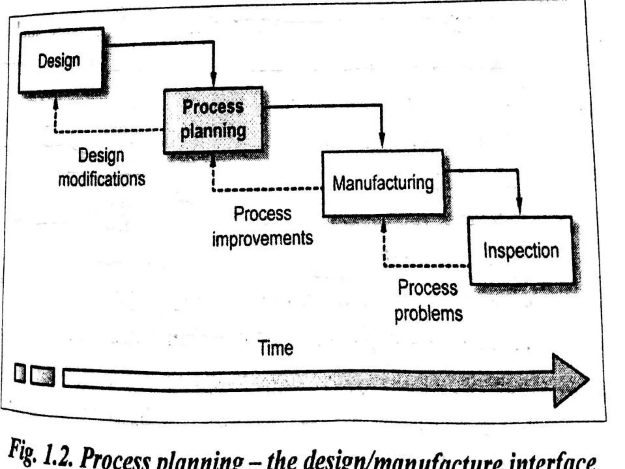
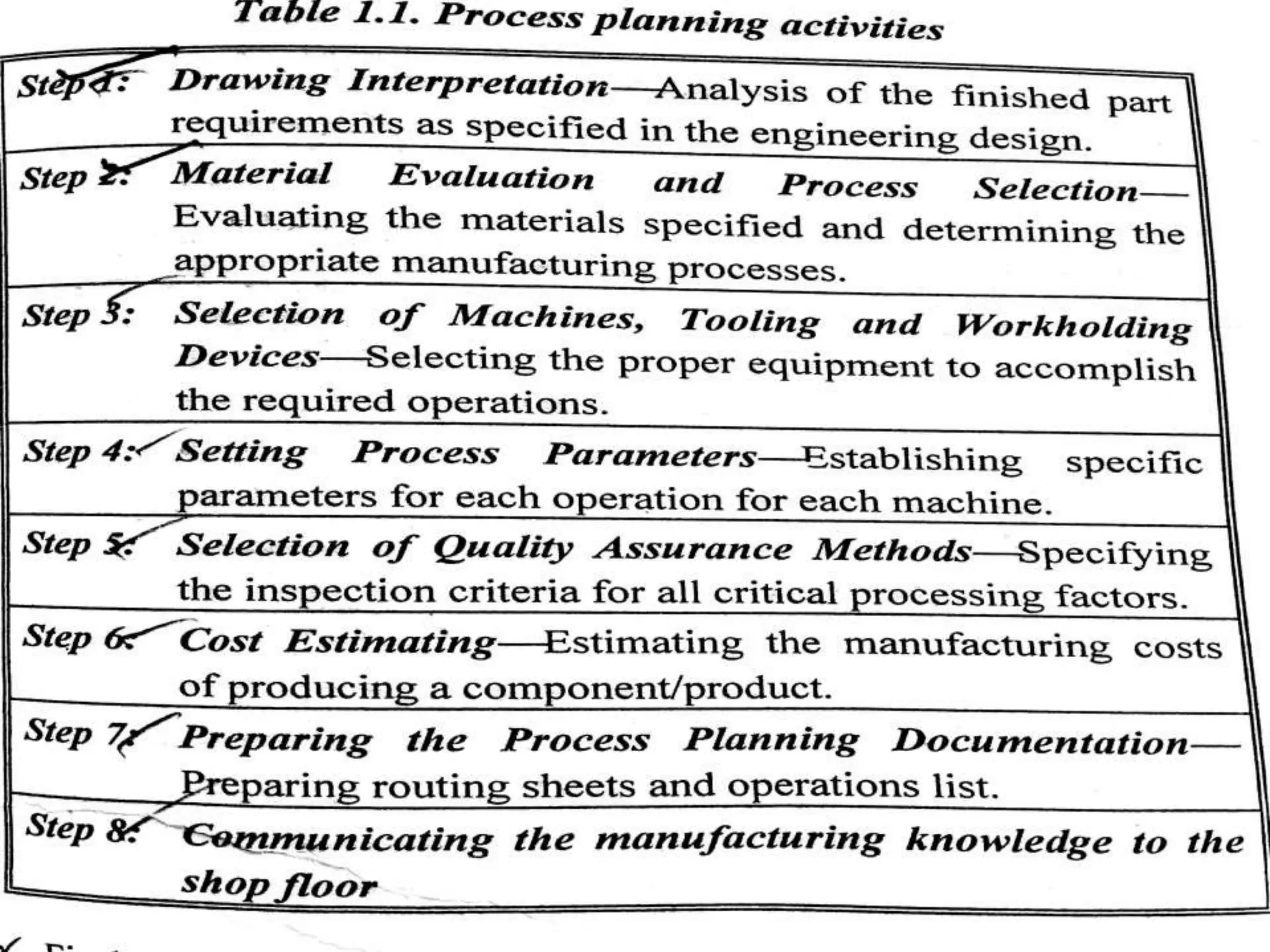
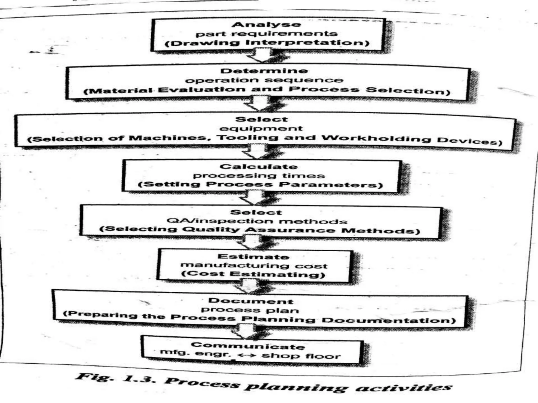
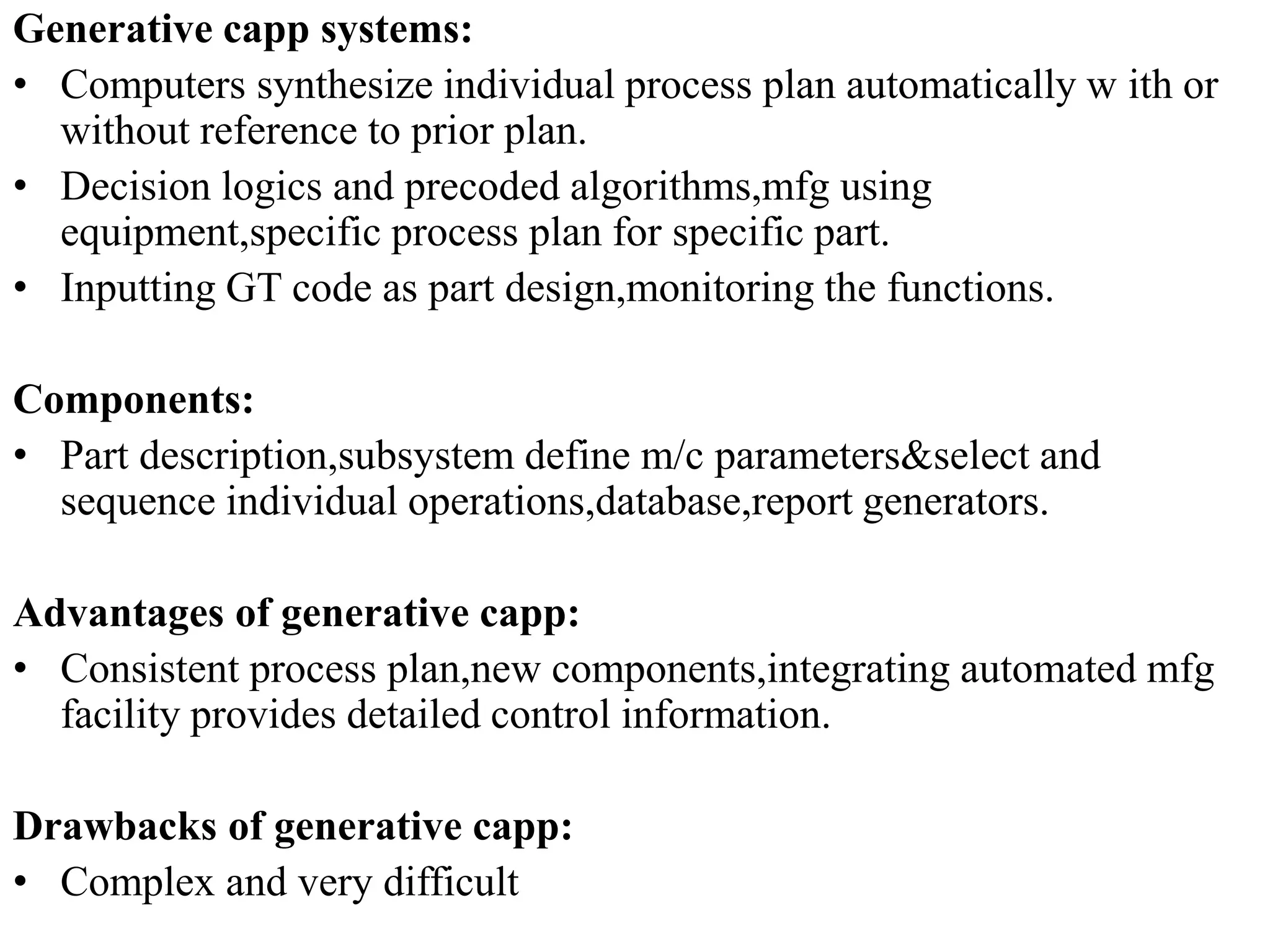
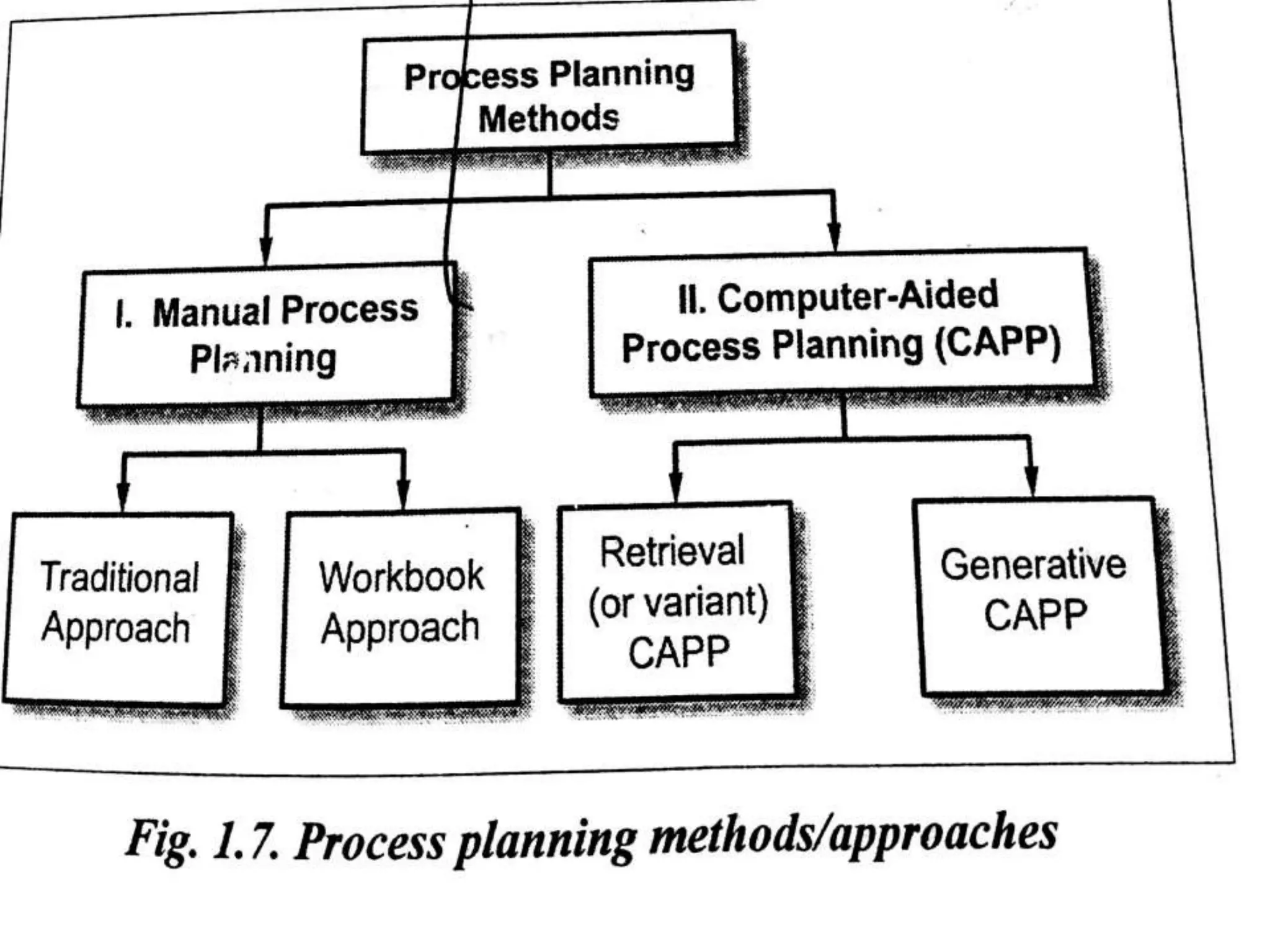
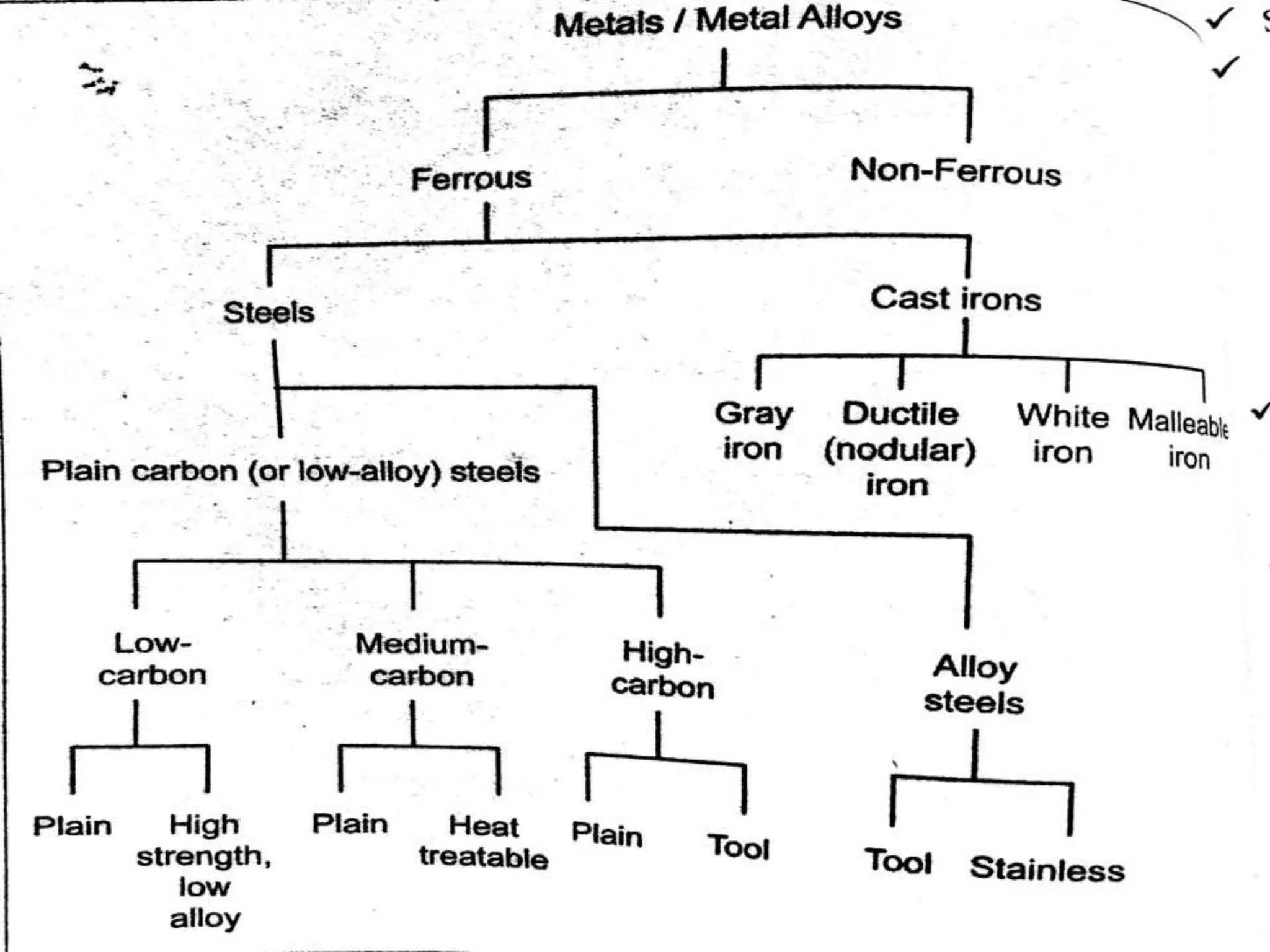
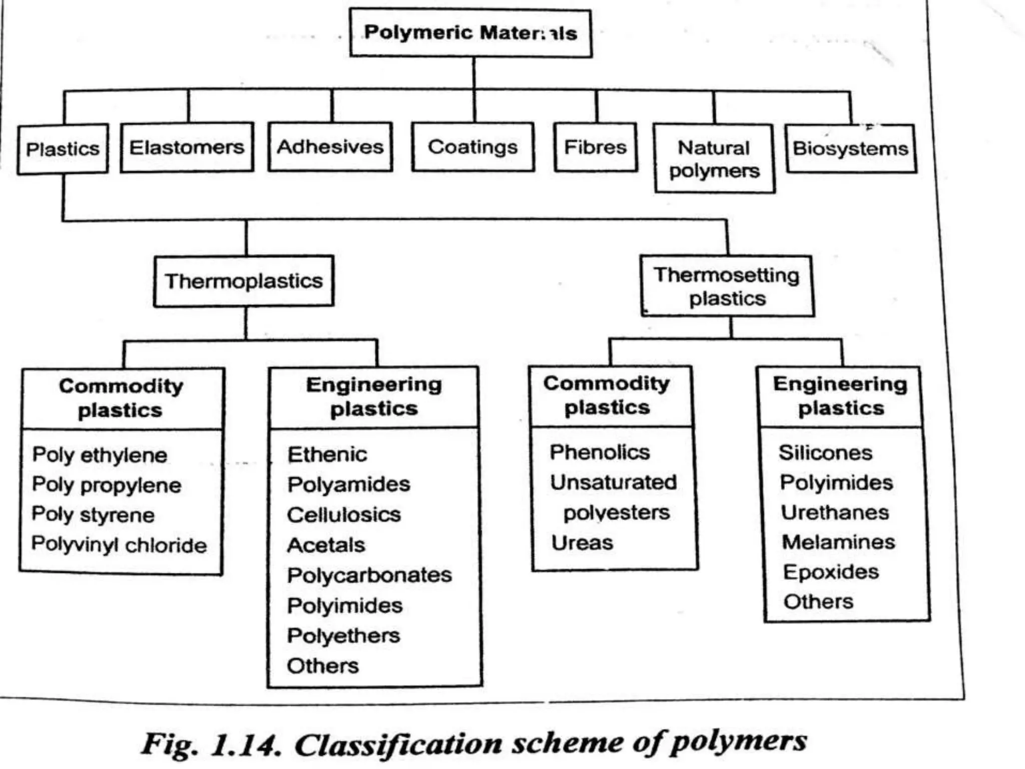
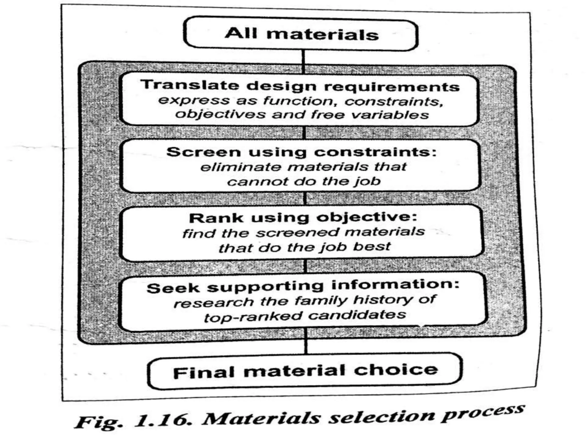
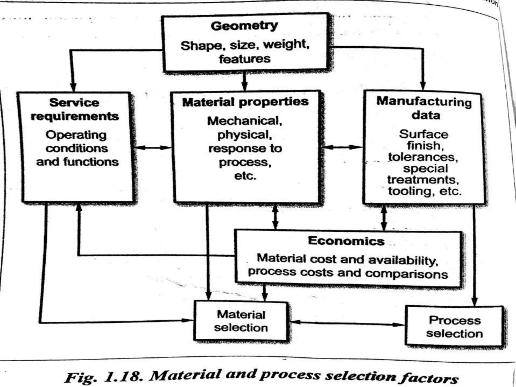
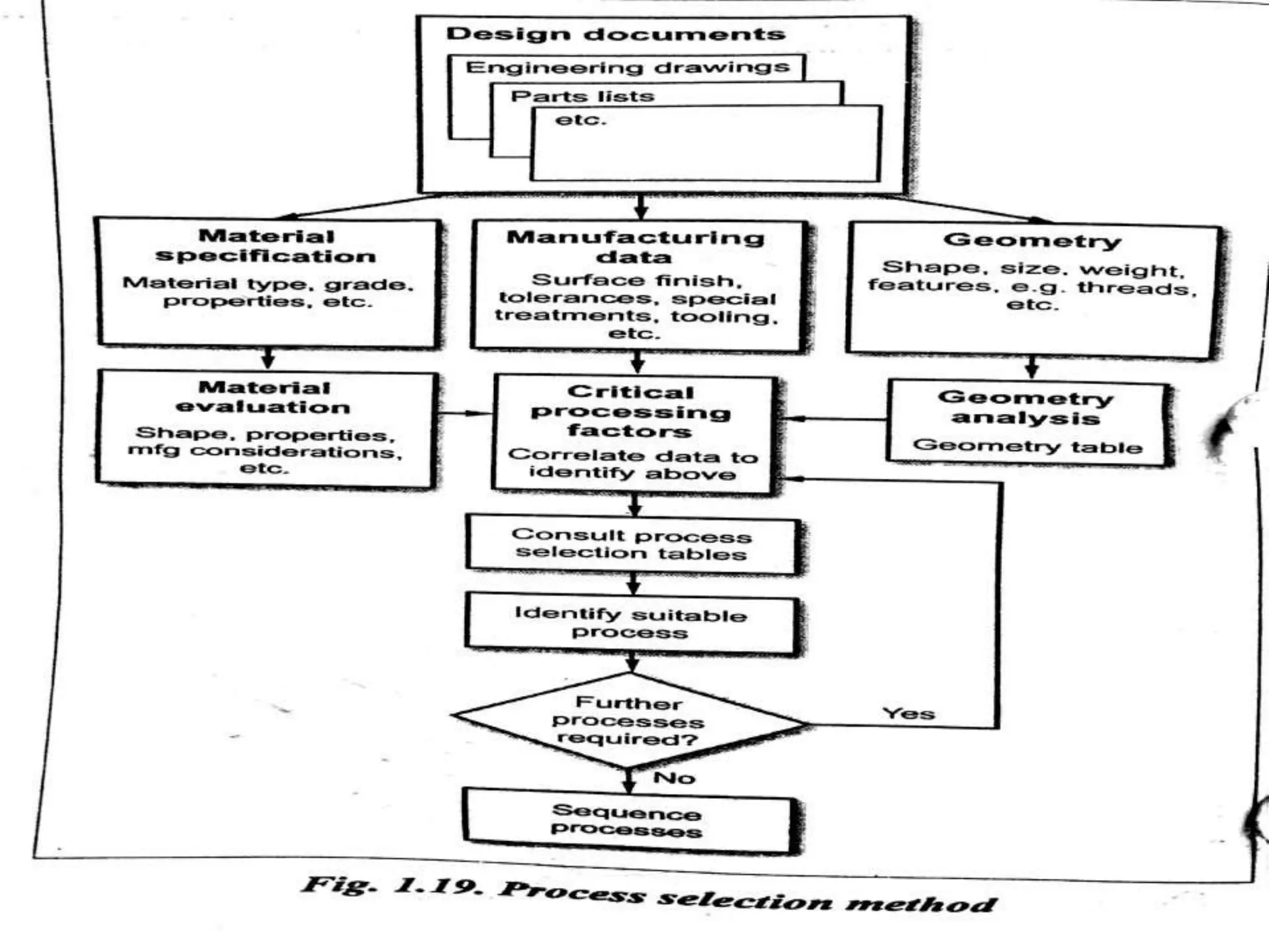
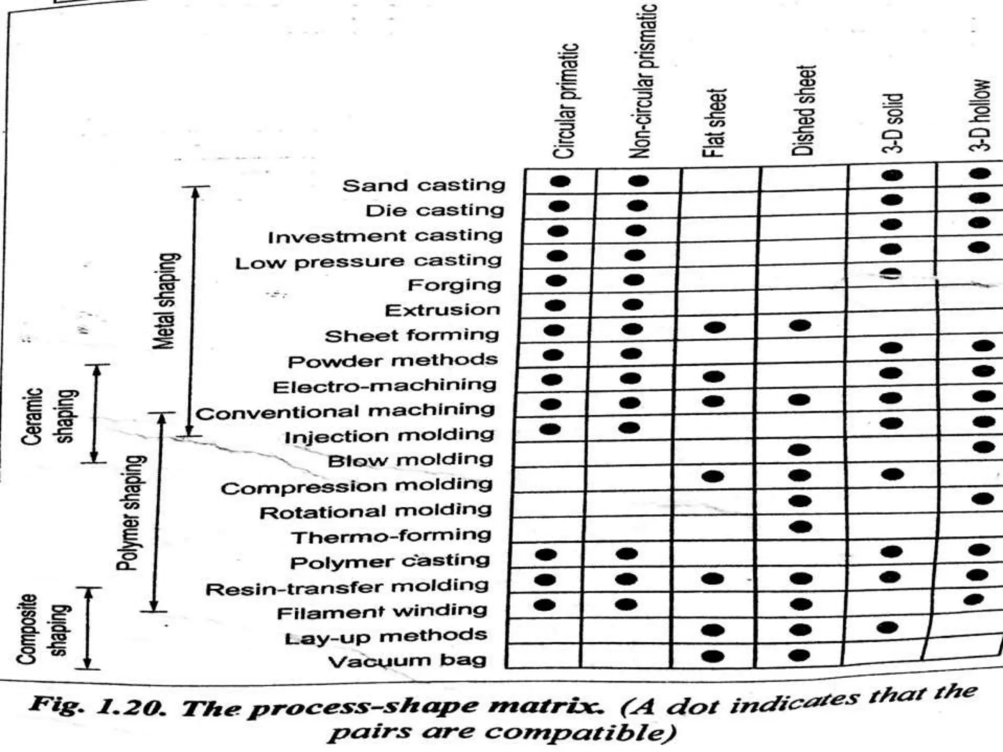
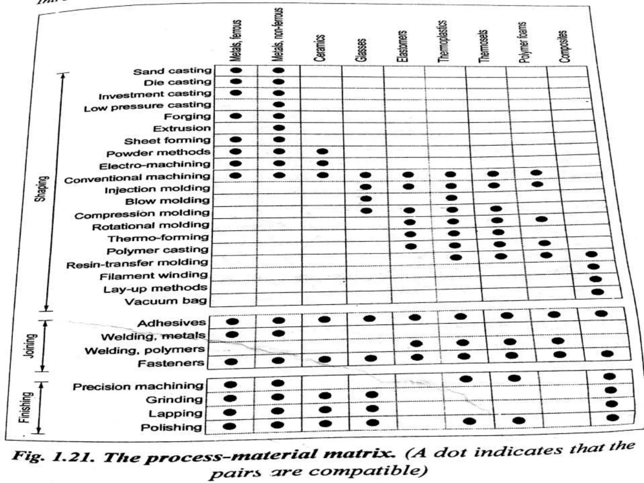
PROCESS PLANNING AND
COST ESTIMATION
U-I
INTRODUCTION TO PROCESS
PLANNING
PROCESS PLANNING DEFINITION:
• Set of instructions describes mfg product and its parts.
• Operations planning as systematic determination of engg processes
and systems to mfg a product competitively and economically.
• Prepare work instructions for mfg and assembly of components to
product in discrete mfg environments.
• Systematic determination of methods products to be
mfg,economically and competitively.
• Consists of selection of mfg processes and operations,production
equipment,tooling and jigs and fixtures,
• Determination of mfg parameters,specify selection criteria for quality
assurance ensure product quality.
IMPORTANCE OF PROCESS PLANNING:
• Link between engg design and shop floor mfg,product is how
mfg,production costs and profitability,indepth of knowledge,
equipment capabilities, tooling availability, material processing
characteristics, shop practices.
PRODUCT DESIGN AND MFG CYCLE:
• Intermediate stage b/w designing the product and mfg.
• Three main functions marketing and sales,design,mfg.
PROCESS PLANNING: LINK B/W DESIGN AND MFG:
• Cross functional teams are employed to design and mfg
functions,known as simultaneous or concurrent engg.
RESPOSIBILITIES OF PROCESS PLANNING ENGINEER:
• Part print analysis and symbols.
• Fundamentals of product design(rough stock, production
rate,finish,dimensional tolerances).
• Machining processes(setup time,quality,type and cost of tooling).
• Operations sequence,inspect the equipment,production
tolerances,cutting tools and cutting conditions,overall time by work
measurement techniques.
PROCESS PLANNING ACTIVITIES:
Drawing interpretation:
• Analyse finished part in engineering design.component
drawings(features,dimensions,geometric tolerances,surface
finish,material specification,part required).
Material evaluation and process selection:
• (Function,appearance,reliability,life,environment,compatibility,produc
tivity,cost).Evaluate the materials, (features,dimensions,geometric
tolerances transform rough state to finished state).Process
evolution(rough to finished).Part evolution(final state to initial state).
Selection of m/c,tooling,workholding devices:
• Economic considerations,production rate per unit cost,durability and
dependability,lower process rejection,minimum setup times,long life
of m/c,functional versatility.best m/c,make or buy,BEA .
Selecting process parameters:
• Machines selected,calculating operation setup time and cycle
time,tooling sequence,equipment capability,shop practice.
• Calculation of part processing time requires determination of
sequence of processing steps on each m/c as outplanning.
• Part loading,unloading,m/c indexing for 1 cycle.
• M/c cycle time allowances added to standard cycle time.Calculate
cycle time & m/c rates to find out cost.
Selecting quality assurance methods:
• Inspection criterias(dimensional,geometric,surface finish),tools and
techniques,increases costs&time.
Cost estimating:
• Process of determining the probable cost of product before
manufacture.
• Material,labour,overhead costs-profit.
• Material,mfg processes,batch size,make or buy.
Process planning documentation:
• Document clearly all the detail information.
• Documented as job routing or operating sheet.
• Production operations&associated m/c tools for component and
subassembly.
• Route sheet information as
part identification,processing,operation of m/c,std times,setup cycle
times,tooling requirements,production control information shows
planning lead time operation.
• Reasons: part process-design,job quote,cost estimate,std cost
systems,communication vehicle.
Communicate process knowledge:
• Mfg to shop floor,economy,consistent quality.
Inputs and outputs of process planning:
• Route sheet and operation sheet as single sheet.
PROCESS PLANNING METHODS(APPROACHES TO PROCESS
PLANNING):
• Manual process planning(traditional,workbook approaches).
• Computer aided process planning(retrieval,generative).
Manual process planning:
Traditional approach:
• Process plan prepared manually.
• Examine and interpret eg,m/c process,equipment selection,opns
sequence,shop practices,skill,judgement and experience,different
planners.
• Product opns,manual tools(feed,speed,setup time,opns
time),documented as routing sheet.
Workbook approach:
• Modified version uses developed workbook prepares route sheet.opns
sequence of products the drawing interpretation is carried by
workbook.
Uses of manual approach:
• Small scale companies,flexible,low investments.
Drawbacks of manual approach:
• Complex,time&data high,skill process,human error,skill,judgement
and experience,increases paper work,productivity down,no response
to mfg environment,process,tool,materials…
Computer aided process planning:
• Computers reduces clerical works,rational,consistent and optimal
plans,interface between cad and cam.
Benefits of capp:
• Process rationalization and standardization,productivity
improvement,product cost reduction,eliminate human error,time
reduction,reduces clerical and paper work,legibility improves,fast
response to engg changes,incorporation of application programs.
Retrieval or variant capp systems:
• Widely used in machining applications,similar parts have similar
plans,new part recalls,identifies,retrieves existing plan for similar
modified new parts.
Benefits of retrieval capp systems:
• Standard plan,variety of parts,simple programming and
installation,understandable,easy to learn and use.
Drawbacks of retrieval capp systems:
• Planned components limited to previous planned.
• Experiences modify standard plan.
Generative capp systems:
• Computers synthesize individual process plan automatically w ith or
without reference to prior plan.
• Decision logics and precoded algorithms,mfg using
equipment,specific process plan for specific part.
• Inputting GT code as part design,monitoring the functions.
Components:
• Part description,subsystem define m/c parameters&select and
sequence individual operations,database,report generators.
Advantages of generative capp:
• Consistent process plan,new components,integrating automated mfg
facility provides detailed control information.
Drawbacks of generative capp:
• Complex and very difficult
SELECTION OF PROCESS PLANNING SYSTEM:
• Numerous engg management decisions,identify,weight and compare
interrelated factors.
• Best process plan-general environment,organisational
structure,technical expertise,needs and objectives of MIS.
DRAWING INTERPRETATION:
• Prepares process plan for product,functional requirements of
design,assembled with dimensions and tolerances.
• Information such as material,designation,coding,no of
parts,weight,dimension of parts,geometric tolerances,size and
accuracy.
• Engineering drawing:Language of engg and
communication,orthographic projection(accurate mfg
design,2D&3D,pictorial gives more information).
Types of drawing:
• Detail drawings:single-part,collective.
• Assembly drawings:single-part,collective.
• Combined drawing.
Detail drawings:
• Provide all the information required for mfg of
product,(dimensions,tolerances,surface finish and material
specifications).
Types: single part,collective single part.
Single part drawings:
• Complete detail information single component mfg without reference
sources.shape,dimension,tolerances,size and locations,heat
treatment,surface finish.
Collective single part drawings:
• One or two dimensions of component are variable,others being
standard.
Assembly drawings:
• Machines and mechanisms consist of numerous parts and a drawing
shows complete product with all components in correct physical
relationship.
Sub-assembly drawings:
• Drawing gives small part of whole assembly.
Types:
• Single part,collective
Single part assembly drawings:
• Information to build single sub-assembly or assembly.
• Part list,quantity,overall dimensions,weight,mtrl specifications,design
data,operational details and instructions.
Collective assembly drawings:
• Range of products similar in appearances,differ in size,mfg and
assembled.
Combined detail and assembly drawings:
• Assembly with part list and details of these parts on one
drawing,small one-off reduces scheduling and printing.
INFORMATION ON THE DRAWING SHEET REQUIRED FOR
PROCESS PLANNING:(CRITICAL PROCESSING FACTORS):
• Dimensions: complete dimensions of the component design mfg.
• Functional: Influence operated part.
• Non-functional: Not influence operated part.
• Auxiliary: Not relate to operate and mfg part.
Material specifications:
• Parts evaluated,specified and manufactured.
Special material treatments:
• Material properties treated.
Tolerances,limits and fits:
• Component fit assembly,appropriate lower and upper limits.
• Accurate tolerance,cost high,good engg practice.
Dimensional tolerances:
• 10±0.02 as 9.98&10.02mm.
General tolerancing:
• Unspecified tolerances dimensions,saves time.
Limits and fits for shafts and holes:
• Basic size is shaft or hole size,limits the specified design.
• Basic hole system-basic hole size adjusts shaft size to fit.
• Basic shaft system-basic shaft size adjusts hole size to fit.
• Standard tools as drills,reamers for basic hole system.
Fit
• Tightness or looseness for application of tolerances to mating parts.
Clearance fit
• Assemble/dissemble by hand,running and sliding assemblies,low cost
to high temperature,minimum accuracy.
Transition fit
• Press tooling,close accuracy,no interference.
Interference fit
• Forced permanent assemblies,retain and locate.
Geometrical tolerancing
• Permissible variation of form,attitude.
Types:straightness,flatness,roundness,cylindricity,parallelism,squareness
angularity,concentricity,symmetry,position.
Surface finish:
• Irregularities depth of surface in mfg processes.
Form error:
• Longer wavelength deviations of surface to nominal surface,large
scale problems,errors in m/c tool ways,guides,inaccurate alignment of
w/p.
Roughness:
• Finest irregularities of surface,production process.
Waviness:
• Widely space deviations from norminal shape,m/c vibration.
• Surface texture=roughness+waviness.
• Surface roughness,surface textures(symbols), Surface
roughness,surface textures(components) used.
Material selection and evaluation:
• Component-material processing-mfg-design.
Metals and classification:
Ferrous materials:
• Materials of iron as prime constituent,steel(0.05-2%),iron(2-4.5%).
Steels:
• Alloys of iron and carbon,carbon steels and alloy steels.
• Low carbon steel 0.25%C,Medium carbon steel 0.60%C,
High carbon steel-0.60%C.
• Alloy steels-chromium,nickel,molybdenum,vanadium,tungsten,cobalt.
• Low alloy steels-3 to 4%,high alloy steels-5%(alloying elements).
• Important alloy steels-stainless steels,tool steels,HSLA
steels,maraging steels.
Cast iron:
• Ferrous alloys of iron 2 to 4.5%C,3.5% silicon.
• Grey cast iron-low cost,white cast iron-hard and brittle,malleable cast
iron-ductile,yield and tensile strength,spheroidal graphite cast iron.
Non-ferrous materials:
• Elements other than iron as chief constituent.
• Light weight,colour,ease fabrication, better resistant, electrical and
thermal conductivity.
• Important non-ferrous materials-C,Al,lead,Ni,Mg,Ti,Tn,Zn.
Polymers:
• Density, thermal and electrical insulation, resist to
chemical,fabrication,low cost.
Engineering ceramics:
• Grinding,deals,bearings,magnets,engines,pumps.
• Features-(melting temp,oxidation,corrosion,high temp).
• Alumina,SiC,Si3N4,PSZ,Sialons.
Composites:
• Composed of two or more different materials, resultant materials
superior to individual materials.
• Particle reinforced composites-Particles of one material dispersed in a
matrix of second material.
• Fibre reinforced composites-Dispersed phase as fibre.
MATERIAL SELECTION PROCESS:
• Appropriate material for product under consideration is complex task.
• Translation-design requirements as constraints,objectives,free
variables.
• Screening-constrained limits apply to subset of viable materials.
• Ranking-ordering material,excellence criteria,maximum or minimum.
• Supporting information-
top-ranked,history,behavior,availability,sufficient choice.
MATERIAL SELECTION METHODS:
• Computer aided databases,performance indices,decision
matrices,expert selection,value analysis,failure analysis,cost-benefit
analysis.
Material evaluation methods:
Shape or geometry considerations:
• Process-mfg-product.
• Size,complexity,dimensional tolerance,surface finish,wear
allowance,assembly,manufacturability.
• Material property requirements-Loading type,loading
magnitude,impact loading,cyclic loading,wear resistance,permissible
temp,material deformation.
• Physical property requirements-
electrical,magnetic,thermal,weight,aesthetic.
• Service requirements- temperatures operating,life span,most
extreme,maintanence,reliability,serviceability,recyclability.
Manufacturing considerations:
• Components,ease mfg,quantity,components rate,minimum&maximum
section thickness,quality level,inspection methods,assembly ease.
PROCESS SELECTION
Process selection
• shaping, joining, finishing, mfg-design, size, shape and
precision,parts.
Factors
• Material form, size and weight, economic considerations, dimensional
and geometry accuracy, surface finish,batch size, production rate.
Guidelines
• Prototype validate mfg,compare mfg to assembly costs for different
processes.
Process selection methods(steps):
Mfg process,difficult,complex and systematic
Assumptions:
• Materials selected,specified.
• Design documents,information comprehensive.
Stages:
Drawing interpretation:
• Starting point for process selection.
• Material,shape,size,tolerance,roughness,process parameters.
• Three analysis and o/p-geometry analysis,mfg information,material
evaluation and o/p.
Identification of critical processing factors:
• Combined o/p from drawing interpretation analysed and correlated.
• Material-mfg-geometry.
Comparison of potential mfg processes:
• Correlate,appropriate,decision-making,economy data.
• (Labour,equipment,tooling cost,batch and production rates),costing
methods and comparisons.
Identification of suitable processes:
• Part-primary-secondary-critical processing.
Production equipment and tooling selection:
• Mfg-processes-production equipment.
Factors for equipment:
• Size,weight,physical size,construction,power and torque, no of tools,
type of tools.
• Equipment-tooling-operation.
Factors for tooling:
• Availability,w/p,type,part geometry,tool material,m/c data,m/c tool
characteristics,cutting tool materials,tool holding,quality,capability
requirements.
• Consumables tooling-cutting tools,workholding devices,jigs and
fixtures.
Factors in equipment selection:
• M/c-processes-mfg-decision making-performing.
Factors for m/c selection:
• Technical factors-physical size,m/c accuracy,surface finish,cutting
forces,power.
• Operational factors-batch size,.Capacity,availability.
Technical factors:
• M/c tool-mfg component/product, physical size,m/c accuracy,surface
finish,cutting forces,power.
Physical size:
• M/c tool-process-product-robust.
Machine accuracy:
• Capability-mfg-dimension&geometry-design.
Surface finish:Capability.
Cutting forces:Feed,speed,depth of cut,opns of m/c tool.
Machine power:Power=cutting forcexcutting speed.
Operational factors: Availability,cost effective,master production
schedule.[Important-batch size,capacity,availability].
Batch size: EBQ calculated,potential economical m/c tool.
Capacity:Production rate,acheives o/p,mps.
Availability:Proportion,performance,efficiency,reliability,
Availability.
Machine selection methods(steps):
First cut selection: Identify,specify,select mfg processes,physical
size,type of machine.
Power/force analysis: Specify.
Capability analysis: Dimensional,geometry accuracy,surface finish,m/c
short listings.
Final selection: More than 1 machine.
Factors in tooling selection:
• Constraints on tool selection- Mfg practice,mfg process,m/c tool
characteristics,capability,processing time, cutting tool availability.
• Operating requirements on tool selection-W/p material,operation,part
geometry, tooling data.
• Tooling performance affecting factors-Cutting tool materials, cutting
tool geometry, cutting fluids.
Constraints on tool selection- Mfg practice,mfg process,m/c tool
characteristics,capability,processing time, cutting tool availability.
Manufacturing practice:
• Tool actually fed to workpiece.
• Two categories(continuous cutting,intermittent cutting).
• Continuous cutting-cutting tool is continuously fed to w/p.
• Intermittent cutting-cutting tool not continuously fed to w/p.
Manufacturing process:
• M/c tools limit the selection of tooling.
M/c tool characteristics:
Work holding devices,Tool structure,Power o/p,
Feed and speed of m/c.
Capability:
• Dimensional and geometric accuracy,surface finish.
Machining time:
• Power,feed,speed,m/c,tooling.
Cutting tool availability:
• Selecting the available tools.
Tool selection operating requirements-W/p materials,operation,part
geometry,tooling data.
Workpiece material:
• Heat generation,cutting tool geometry material.
Operation:
• Specific cutting tool.
Part geometry:
• Specific geometry feature.
Tooling data:
• Mfg tooling data,suitable tools,specified operations.
Tooling performance factors- cutting tool materials,cutting tool
geometry,cutting fluids.
Cutting tool materials:
• Tool performance,hss,carbides,cast non-ferrous alloys,ceramics.
Cutting tool geometry:
• Tool angles,rake angles,cutting edge angles,tool nose radius.
• Influences w/p material and tool material.
Cutting fluids usage:
• Cools w/p,tool temperature,maintains hardness,avoid distortion.
• Friction b/w tool and w/p,wear resistance of tool,improves tool
performance.
INTRODUCTION TO PROCESS PLANNING

INTRODUCTION TO PROCESS PLANNING

  • 1.
  • 2.
  • 3.
    PROCESS PLANNING DEFINITION: •Set of instructions describes mfg product and its parts. • Operations planning as systematic determination of engg processes and systems to mfg a product competitively and economically. • Prepare work instructions for mfg and assembly of components to product in discrete mfg environments. • Systematic determination of methods products to be mfg,economically and competitively. • Consists of selection of mfg processes and operations,production equipment,tooling and jigs and fixtures,
  • 4.
    • Determination ofmfg parameters,specify selection criteria for quality assurance ensure product quality. IMPORTANCE OF PROCESS PLANNING: • Link between engg design and shop floor mfg,product is how mfg,production costs and profitability,indepth of knowledge, equipment capabilities, tooling availability, material processing characteristics, shop practices. PRODUCT DESIGN AND MFG CYCLE: • Intermediate stage b/w designing the product and mfg. • Three main functions marketing and sales,design,mfg.
  • 6.
    PROCESS PLANNING: LINKB/W DESIGN AND MFG: • Cross functional teams are employed to design and mfg functions,known as simultaneous or concurrent engg.
  • 8.
    RESPOSIBILITIES OF PROCESSPLANNING ENGINEER: • Part print analysis and symbols. • Fundamentals of product design(rough stock, production rate,finish,dimensional tolerances). • Machining processes(setup time,quality,type and cost of tooling). • Operations sequence,inspect the equipment,production tolerances,cutting tools and cutting conditions,overall time by work measurement techniques.
  • 14.
    PROCESS PLANNING ACTIVITIES: Drawinginterpretation: • Analyse finished part in engineering design.component drawings(features,dimensions,geometric tolerances,surface finish,material specification,part required). Material evaluation and process selection: • (Function,appearance,reliability,life,environment,compatibility,produc tivity,cost).Evaluate the materials, (features,dimensions,geometric tolerances transform rough state to finished state).Process evolution(rough to finished).Part evolution(final state to initial state).
  • 15.
    Selection of m/c,tooling,workholdingdevices: • Economic considerations,production rate per unit cost,durability and dependability,lower process rejection,minimum setup times,long life of m/c,functional versatility.best m/c,make or buy,BEA . Selecting process parameters: • Machines selected,calculating operation setup time and cycle time,tooling sequence,equipment capability,shop practice. • Calculation of part processing time requires determination of sequence of processing steps on each m/c as outplanning. • Part loading,unloading,m/c indexing for 1 cycle. • M/c cycle time allowances added to standard cycle time.Calculate cycle time & m/c rates to find out cost.
  • 16.
    Selecting quality assurancemethods: • Inspection criterias(dimensional,geometric,surface finish),tools and techniques,increases costs&time. Cost estimating: • Process of determining the probable cost of product before manufacture. • Material,labour,overhead costs-profit. • Material,mfg processes,batch size,make or buy.
  • 17.
    Process planning documentation: •Document clearly all the detail information. • Documented as job routing or operating sheet. • Production operations&associated m/c tools for component and subassembly. • Route sheet information as part identification,processing,operation of m/c,std times,setup cycle times,tooling requirements,production control information shows planning lead time operation. • Reasons: part process-design,job quote,cost estimate,std cost systems,communication vehicle.
  • 18.
    Communicate process knowledge: •Mfg to shop floor,economy,consistent quality. Inputs and outputs of process planning: • Route sheet and operation sheet as single sheet.
  • 19.
    PROCESS PLANNING METHODS(APPROACHESTO PROCESS PLANNING): • Manual process planning(traditional,workbook approaches). • Computer aided process planning(retrieval,generative). Manual process planning: Traditional approach: • Process plan prepared manually. • Examine and interpret eg,m/c process,equipment selection,opns sequence,shop practices,skill,judgement and experience,different planners. • Product opns,manual tools(feed,speed,setup time,opns time),documented as routing sheet.
  • 20.
    Workbook approach: • Modifiedversion uses developed workbook prepares route sheet.opns sequence of products the drawing interpretation is carried by workbook. Uses of manual approach: • Small scale companies,flexible,low investments. Drawbacks of manual approach: • Complex,time&data high,skill process,human error,skill,judgement and experience,increases paper work,productivity down,no response to mfg environment,process,tool,materials… Computer aided process planning: • Computers reduces clerical works,rational,consistent and optimal plans,interface between cad and cam.
  • 21.
    Benefits of capp: •Process rationalization and standardization,productivity improvement,product cost reduction,eliminate human error,time reduction,reduces clerical and paper work,legibility improves,fast response to engg changes,incorporation of application programs. Retrieval or variant capp systems: • Widely used in machining applications,similar parts have similar plans,new part recalls,identifies,retrieves existing plan for similar modified new parts. Benefits of retrieval capp systems: • Standard plan,variety of parts,simple programming and installation,understandable,easy to learn and use. Drawbacks of retrieval capp systems: • Planned components limited to previous planned. • Experiences modify standard plan.
  • 22.
    Generative capp systems: •Computers synthesize individual process plan automatically w ith or without reference to prior plan. • Decision logics and precoded algorithms,mfg using equipment,specific process plan for specific part. • Inputting GT code as part design,monitoring the functions. Components: • Part description,subsystem define m/c parameters&select and sequence individual operations,database,report generators. Advantages of generative capp: • Consistent process plan,new components,integrating automated mfg facility provides detailed control information. Drawbacks of generative capp: • Complex and very difficult
  • 25.
    SELECTION OF PROCESSPLANNING SYSTEM: • Numerous engg management decisions,identify,weight and compare interrelated factors. • Best process plan-general environment,organisational structure,technical expertise,needs and objectives of MIS.
  • 30.
    DRAWING INTERPRETATION: • Preparesprocess plan for product,functional requirements of design,assembled with dimensions and tolerances. • Information such as material,designation,coding,no of parts,weight,dimension of parts,geometric tolerances,size and accuracy. • Engineering drawing:Language of engg and communication,orthographic projection(accurate mfg design,2D&3D,pictorial gives more information). Types of drawing: • Detail drawings:single-part,collective. • Assembly drawings:single-part,collective. • Combined drawing. Detail drawings: • Provide all the information required for mfg of product,(dimensions,tolerances,surface finish and material specifications).
  • 31.
    Types: single part,collectivesingle part. Single part drawings: • Complete detail information single component mfg without reference sources.shape,dimension,tolerances,size and locations,heat treatment,surface finish. Collective single part drawings: • One or two dimensions of component are variable,others being standard. Assembly drawings: • Machines and mechanisms consist of numerous parts and a drawing shows complete product with all components in correct physical relationship. Sub-assembly drawings: • Drawing gives small part of whole assembly. Types: • Single part,collective
  • 32.
    Single part assemblydrawings: • Information to build single sub-assembly or assembly. • Part list,quantity,overall dimensions,weight,mtrl specifications,design data,operational details and instructions. Collective assembly drawings: • Range of products similar in appearances,differ in size,mfg and assembled. Combined detail and assembly drawings: • Assembly with part list and details of these parts on one drawing,small one-off reduces scheduling and printing. INFORMATION ON THE DRAWING SHEET REQUIRED FOR PROCESS PLANNING:(CRITICAL PROCESSING FACTORS): • Dimensions: complete dimensions of the component design mfg. • Functional: Influence operated part. • Non-functional: Not influence operated part. • Auxiliary: Not relate to operate and mfg part.
  • 33.
    Material specifications: • Partsevaluated,specified and manufactured. Special material treatments: • Material properties treated. Tolerances,limits and fits: • Component fit assembly,appropriate lower and upper limits. • Accurate tolerance,cost high,good engg practice. Dimensional tolerances: • 10±0.02 as 9.98&10.02mm. General tolerancing: • Unspecified tolerances dimensions,saves time. Limits and fits for shafts and holes: • Basic size is shaft or hole size,limits the specified design. • Basic hole system-basic hole size adjusts shaft size to fit. • Basic shaft system-basic shaft size adjusts hole size to fit.
  • 34.
    • Standard toolsas drills,reamers for basic hole system. Fit • Tightness or looseness for application of tolerances to mating parts. Clearance fit • Assemble/dissemble by hand,running and sliding assemblies,low cost to high temperature,minimum accuracy. Transition fit • Press tooling,close accuracy,no interference. Interference fit • Forced permanent assemblies,retain and locate. Geometrical tolerancing • Permissible variation of form,attitude. Types:straightness,flatness,roundness,cylindricity,parallelism,squareness angularity,concentricity,symmetry,position.
  • 35.
    Surface finish: • Irregularitiesdepth of surface in mfg processes. Form error: • Longer wavelength deviations of surface to nominal surface,large scale problems,errors in m/c tool ways,guides,inaccurate alignment of w/p. Roughness: • Finest irregularities of surface,production process. Waviness: • Widely space deviations from norminal shape,m/c vibration. • Surface texture=roughness+waviness. • Surface roughness,surface textures(symbols), Surface roughness,surface textures(components) used.
  • 41.
    Material selection andevaluation: • Component-material processing-mfg-design. Metals and classification: Ferrous materials: • Materials of iron as prime constituent,steel(0.05-2%),iron(2-4.5%). Steels: • Alloys of iron and carbon,carbon steels and alloy steels. • Low carbon steel 0.25%C,Medium carbon steel 0.60%C, High carbon steel-0.60%C. • Alloy steels-chromium,nickel,molybdenum,vanadium,tungsten,cobalt. • Low alloy steels-3 to 4%,high alloy steels-5%(alloying elements). • Important alloy steels-stainless steels,tool steels,HSLA steels,maraging steels. Cast iron: • Ferrous alloys of iron 2 to 4.5%C,3.5% silicon.
  • 42.
    • Grey castiron-low cost,white cast iron-hard and brittle,malleable cast iron-ductile,yield and tensile strength,spheroidal graphite cast iron. Non-ferrous materials: • Elements other than iron as chief constituent. • Light weight,colour,ease fabrication, better resistant, electrical and thermal conductivity. • Important non-ferrous materials-C,Al,lead,Ni,Mg,Ti,Tn,Zn. Polymers: • Density, thermal and electrical insulation, resist to chemical,fabrication,low cost. Engineering ceramics: • Grinding,deals,bearings,magnets,engines,pumps. • Features-(melting temp,oxidation,corrosion,high temp). • Alumina,SiC,Si3N4,PSZ,Sialons.
  • 43.
    Composites: • Composed oftwo or more different materials, resultant materials superior to individual materials. • Particle reinforced composites-Particles of one material dispersed in a matrix of second material. • Fibre reinforced composites-Dispersed phase as fibre.
  • 45.
    MATERIAL SELECTION PROCESS: •Appropriate material for product under consideration is complex task. • Translation-design requirements as constraints,objectives,free variables. • Screening-constrained limits apply to subset of viable materials. • Ranking-ordering material,excellence criteria,maximum or minimum. • Supporting information- top-ranked,history,behavior,availability,sufficient choice. MATERIAL SELECTION METHODS: • Computer aided databases,performance indices,decision matrices,expert selection,value analysis,failure analysis,cost-benefit analysis.
  • 47.
    Material evaluation methods: Shapeor geometry considerations: • Process-mfg-product. • Size,complexity,dimensional tolerance,surface finish,wear allowance,assembly,manufacturability. • Material property requirements-Loading type,loading magnitude,impact loading,cyclic loading,wear resistance,permissible temp,material deformation. • Physical property requirements- electrical,magnetic,thermal,weight,aesthetic. • Service requirements- temperatures operating,life span,most extreme,maintanence,reliability,serviceability,recyclability. Manufacturing considerations: • Components,ease mfg,quantity,components rate,minimum&maximum section thickness,quality level,inspection methods,assembly ease.
  • 48.
  • 49.
    Process selection • shaping,joining, finishing, mfg-design, size, shape and precision,parts. Factors • Material form, size and weight, economic considerations, dimensional and geometry accuracy, surface finish,batch size, production rate. Guidelines • Prototype validate mfg,compare mfg to assembly costs for different processes.
  • 55.
    Process selection methods(steps): Mfgprocess,difficult,complex and systematic Assumptions: • Materials selected,specified. • Design documents,information comprehensive. Stages: Drawing interpretation: • Starting point for process selection. • Material,shape,size,tolerance,roughness,process parameters. • Three analysis and o/p-geometry analysis,mfg information,material evaluation and o/p. Identification of critical processing factors: • Combined o/p from drawing interpretation analysed and correlated. • Material-mfg-geometry. Comparison of potential mfg processes:
  • 56.
    • Correlate,appropriate,decision-making,economy data. •(Labour,equipment,tooling cost,batch and production rates),costing methods and comparisons. Identification of suitable processes: • Part-primary-secondary-critical processing. Production equipment and tooling selection: • Mfg-processes-production equipment. Factors for equipment: • Size,weight,physical size,construction,power and torque, no of tools, type of tools. • Equipment-tooling-operation. Factors for tooling: • Availability,w/p,type,part geometry,tool material,m/c data,m/c tool characteristics,cutting tool materials,tool holding,quality,capability requirements.
  • 57.
    • Consumables tooling-cuttingtools,workholding devices,jigs and fixtures. Factors in equipment selection: • M/c-processes-mfg-decision making-performing. Factors for m/c selection: • Technical factors-physical size,m/c accuracy,surface finish,cutting forces,power. • Operational factors-batch size,.Capacity,availability. Technical factors: • M/c tool-mfg component/product, physical size,m/c accuracy,surface finish,cutting forces,power. Physical size: • M/c tool-process-product-robust. Machine accuracy: • Capability-mfg-dimension&geometry-design.
  • 58.
    Surface finish:Capability. Cutting forces:Feed,speed,depthof cut,opns of m/c tool. Machine power:Power=cutting forcexcutting speed. Operational factors: Availability,cost effective,master production schedule.[Important-batch size,capacity,availability]. Batch size: EBQ calculated,potential economical m/c tool. Capacity:Production rate,acheives o/p,mps. Availability:Proportion,performance,efficiency,reliability, Availability.
  • 60.
    Machine selection methods(steps): Firstcut selection: Identify,specify,select mfg processes,physical size,type of machine. Power/force analysis: Specify. Capability analysis: Dimensional,geometry accuracy,surface finish,m/c short listings. Final selection: More than 1 machine.
  • 62.
    Factors in toolingselection: • Constraints on tool selection- Mfg practice,mfg process,m/c tool characteristics,capability,processing time, cutting tool availability. • Operating requirements on tool selection-W/p material,operation,part geometry, tooling data. • Tooling performance affecting factors-Cutting tool materials, cutting tool geometry, cutting fluids. Constraints on tool selection- Mfg practice,mfg process,m/c tool characteristics,capability,processing time, cutting tool availability. Manufacturing practice: • Tool actually fed to workpiece. • Two categories(continuous cutting,intermittent cutting). • Continuous cutting-cutting tool is continuously fed to w/p. • Intermittent cutting-cutting tool not continuously fed to w/p. Manufacturing process: • M/c tools limit the selection of tooling.
  • 63.
    M/c tool characteristics: Workholding devices,Tool structure,Power o/p, Feed and speed of m/c. Capability: • Dimensional and geometric accuracy,surface finish. Machining time: • Power,feed,speed,m/c,tooling. Cutting tool availability: • Selecting the available tools. Tool selection operating requirements-W/p materials,operation,part geometry,tooling data. Workpiece material: • Heat generation,cutting tool geometry material. Operation: • Specific cutting tool.
  • 64.
    Part geometry: • Specificgeometry feature. Tooling data: • Mfg tooling data,suitable tools,specified operations. Tooling performance factors- cutting tool materials,cutting tool geometry,cutting fluids. Cutting tool materials: • Tool performance,hss,carbides,cast non-ferrous alloys,ceramics. Cutting tool geometry: • Tool angles,rake angles,cutting edge angles,tool nose radius. • Influences w/p material and tool material. Cutting fluids usage: • Cools w/p,tool temperature,maintains hardness,avoid distortion. • Friction b/w tool and w/p,wear resistance of tool,improves tool performance.