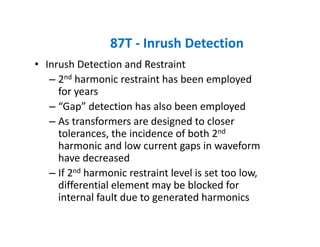
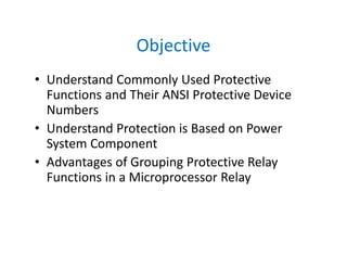
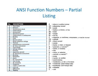
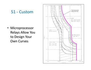
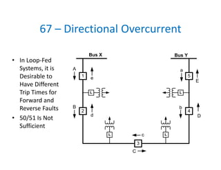
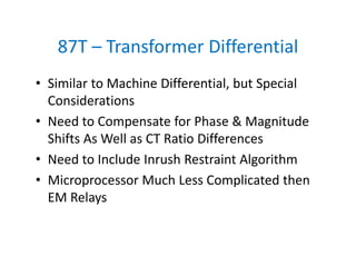
This document provides an overview of commonly used protective relay functions and their ANSI device numbers. It discusses instantaneous overcurrent (50), time overcurrent (51), directional overcurrent (67), reclosing relay (79), and under/over frequency (81O/U) functions. It explains how these functions work, their settings, and considerations for coordination between devices to ensure selective tripping during faults. Microprocessor relays allow for customized curves and grouping of protective functions.


![• Pick up set to 0.05 to 0.1 pu (based on phase CT primary)
• Slope 1 for “normal” errors: 10%
• Break 1 at IEEE calculated worse case remnance point (assume 80% flux)
• Break 2 at 5X times Break 1 (assume no DC offset)
• Slope 2 for large errors: 50‐80%
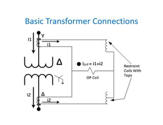
ID
= I1
+ I2
IR
= Max [I1
or I2
]
87T ‐ Differential Characteristic](https://image.slidesharecdn.com/201105fundamentalsofmicroprocessorbasedrelaying-151228021210/85/Fundamentals-of-Microprocessor-Based-Relays-76-320.jpg)
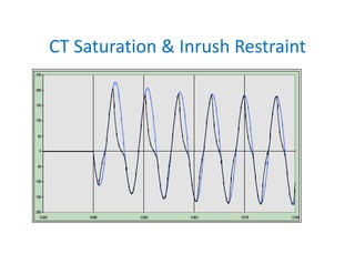
![87T ‐ Through Current: Perfect Waves
0
-4
+4
4 pu
87
0 2 4 6 8 10
2
4
6
8
10
BA
A
IR
= Max [I1
or I2
]
ID = I1 + I2
B
TRIP
RESTRAIN](https://image.slidesharecdn.com/201105fundamentalsofmicroprocessorbasedrelaying-151228021210/85/Fundamentals-of-Microprocessor-Based-Relays-77-320.jpg)
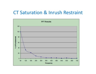
![87T ‐ Through Current: Imperfect Waves
0
-4
+4
4 pu
87
0 2 4 6 8 10
2
4
6
8
10
C
A
A
IR
= Max [I1
or I2
]
ID
= I1
+ I2
B
B (2, -4)
(0,0)
(1, -3)
C
TRIP
RESTRAIN](https://image.slidesharecdn.com/201105fundamentalsofmicroprocessorbasedrelaying-151228021210/85/Fundamentals-of-Microprocessor-Based-Relays-78-320.jpg)
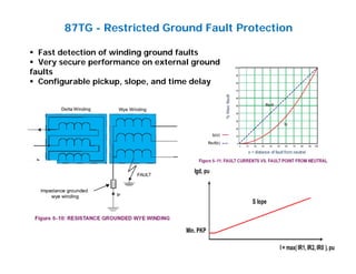
![87T ‐ Internal Fault: Perfect Waves
0
-4
+4
4 pu
87
0 2 4 6 8 10
2
4
6
8
10
BA
A
IR
= Max [I1
or I2
]
ID
= I1
+ I2
B
TRIP
RESTRAIN
4 pu](https://image.slidesharecdn.com/201105fundamentalsofmicroprocessorbasedrelaying-151228021210/85/Fundamentals-of-Microprocessor-Based-Relays-79-320.jpg)
![87T ‐ Internal Fault: Imperfect Waves
0
-4
+4
4 pu
87
0 2 4 6 8 10
2
4
6
8
10
A B
A
IR
= Max [I1
or I2
]
ID = I1 + I2
B
TRIP
RESTRAIN
4 pu
(4, 1.5)](https://image.slidesharecdn.com/201105fundamentalsofmicroprocessorbasedrelaying-151228021210/85/Fundamentals-of-Microprocessor-Based-Relays-80-320.jpg)