Downloaded 191 times

![Generate PWM signal in MATLAB Simulink
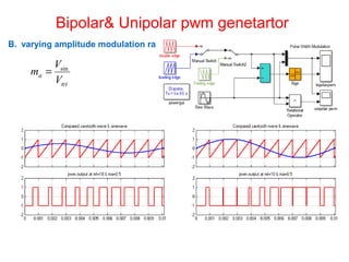
A.Varying Frequency modulation ratio
sinf
f
m tri
f =
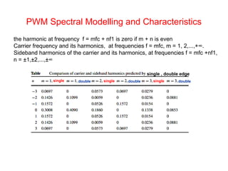
The binary PWM output
can be mathematically written as
( ) ( ) ( )[ ]tctrtb pwm −= sgn](https://image.slidesharecdn.com/dcmotorspeedcontrollerbypwmtechnique-160606101744/85/Dc-motor-speed-controller-by-pwm-technique-4-320.jpg)
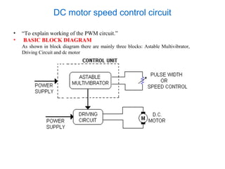
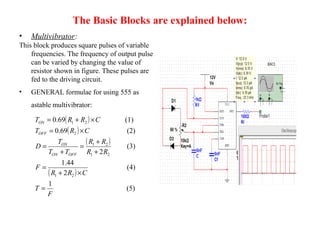
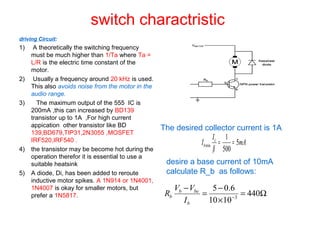
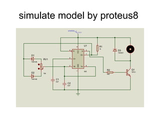
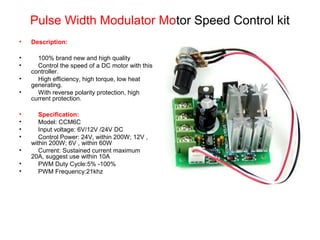

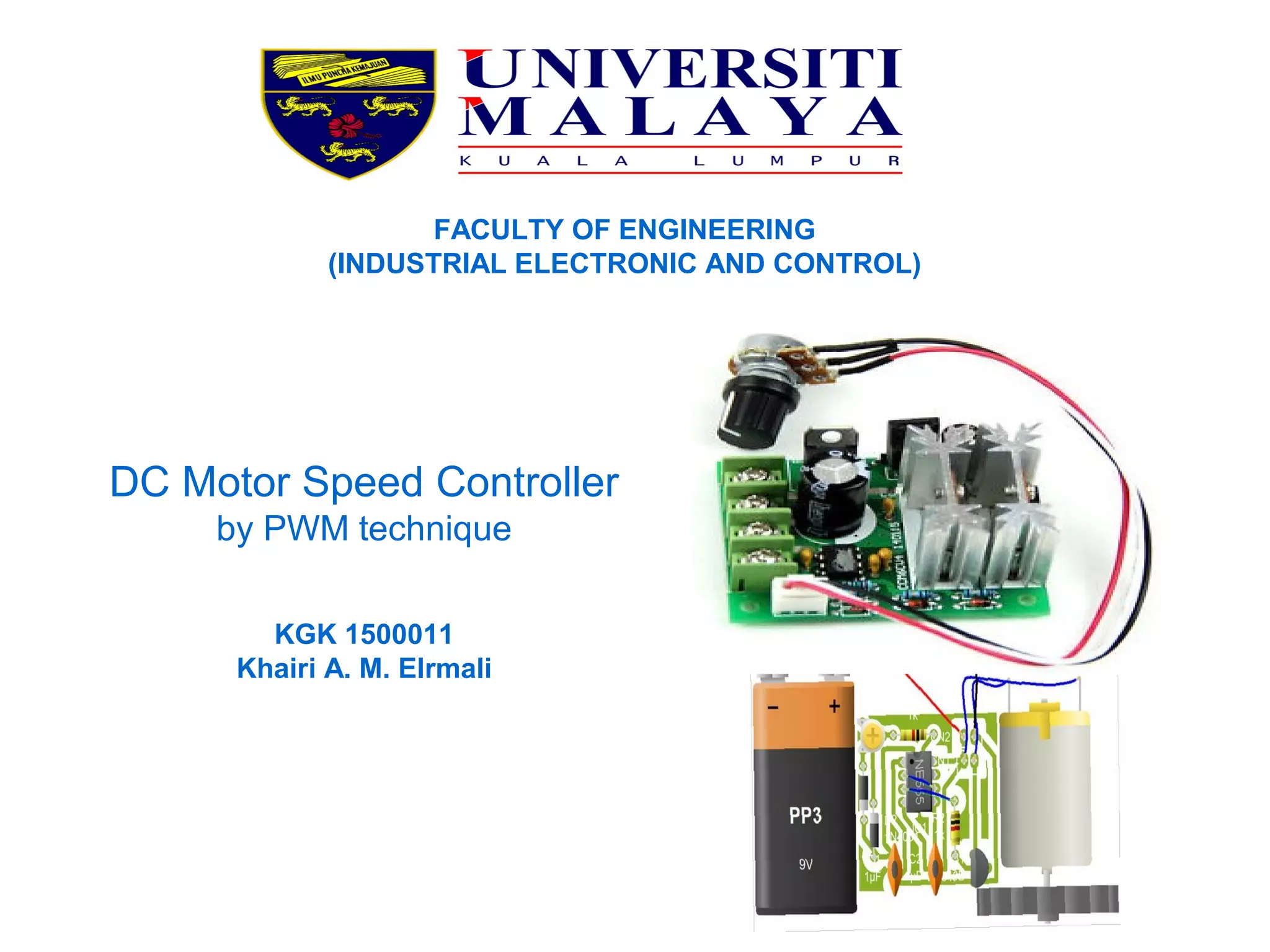
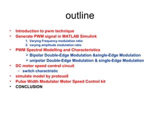
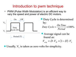
The document discusses the PWM (pulse width modulation) technique for controlling the speed of DC motors, detailing the generation of PWM signals using MATLAB Simulink and spectral modeling. It describes a DC motor speed control circuit comprising an astable multivibrator, driving circuits, and the motor, along with the specifications and operation of a PWM motor speed control kit. Conclusions highlight the motor's response to average pulse values rather than individual pulses, emphasizing the impact of duty cycle variations on speed regulation.