The document presents an overview of protection schemes in electrical engineering, detailing the principles, significance, and types of protective devices and relays. It covers fault causes, protection methods, grounding techniques, and the essential qualities necessary for robustness in power systems. The content emphasizes the importance of swift isolation of faults to maintain system reliability and to minimize damage in electrical networks.
![Ungrounded Neutral System Grounding
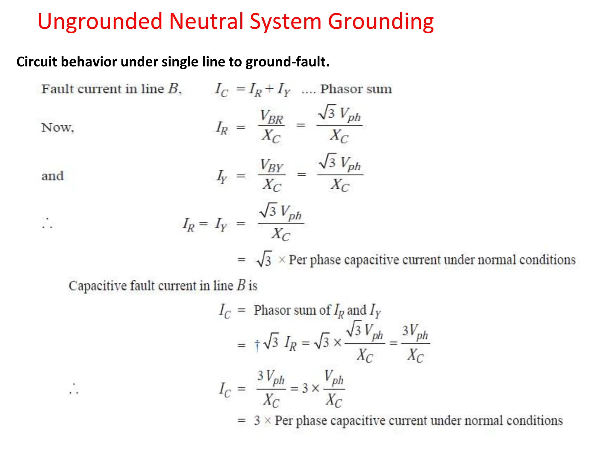
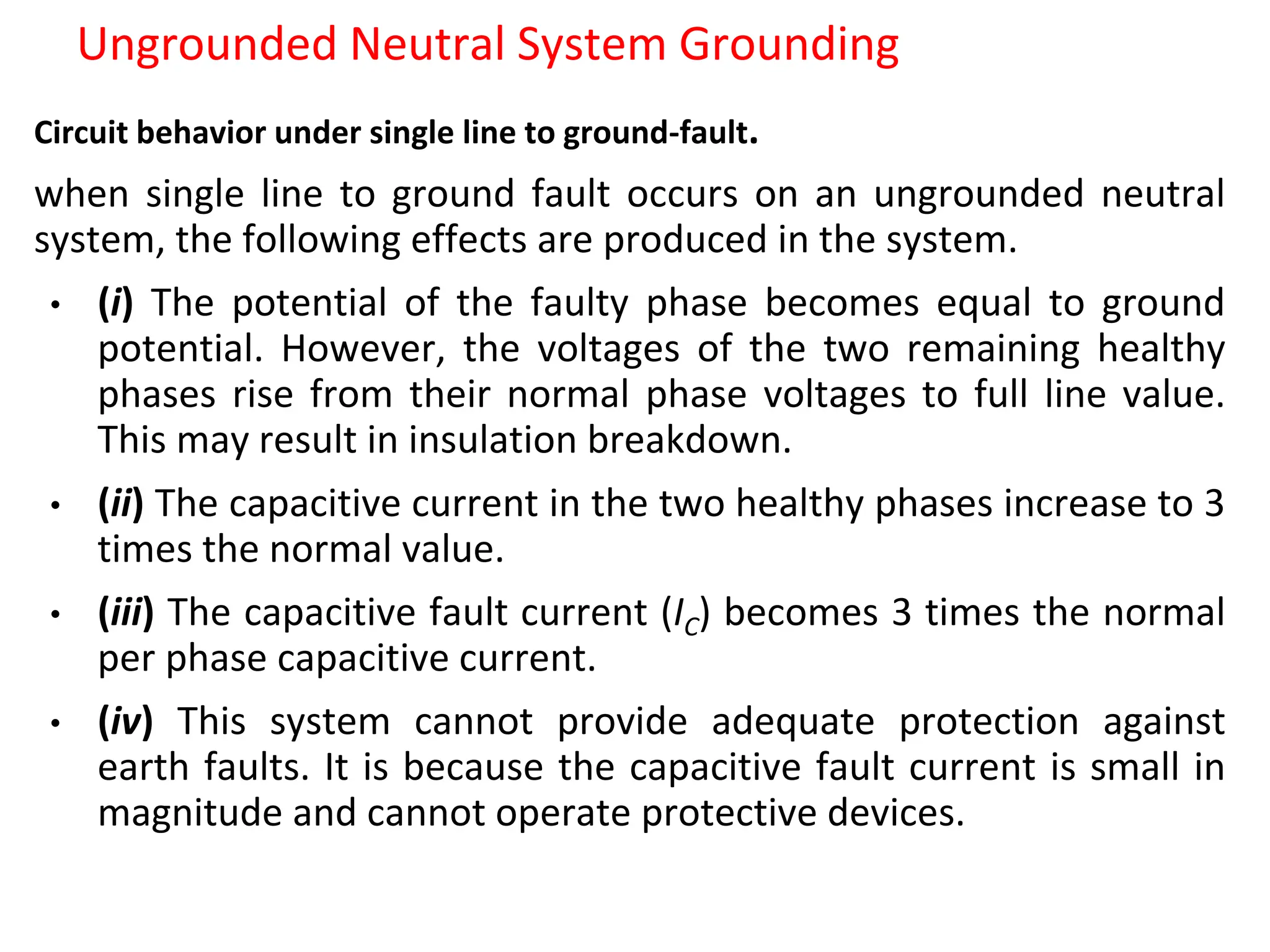
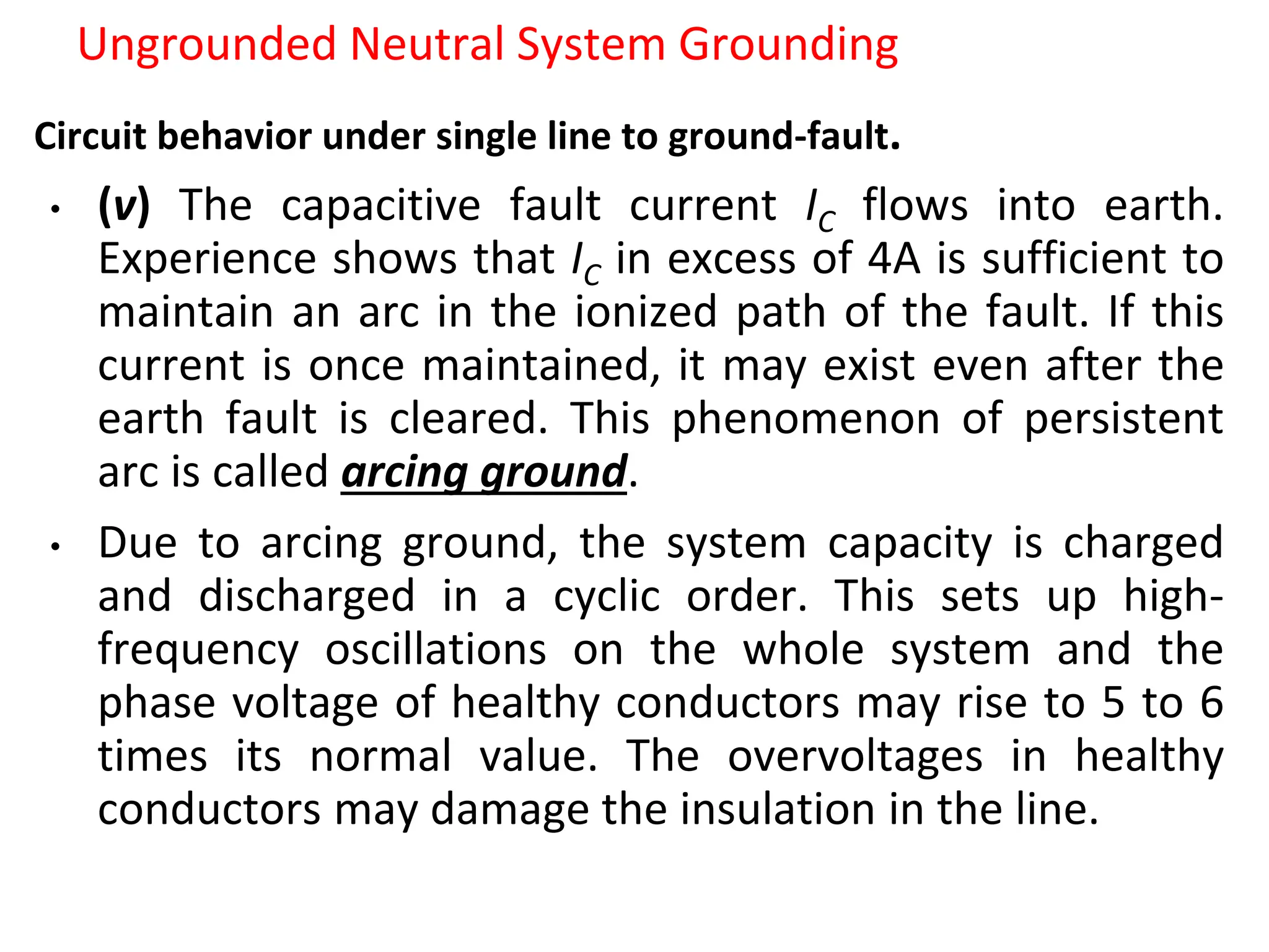
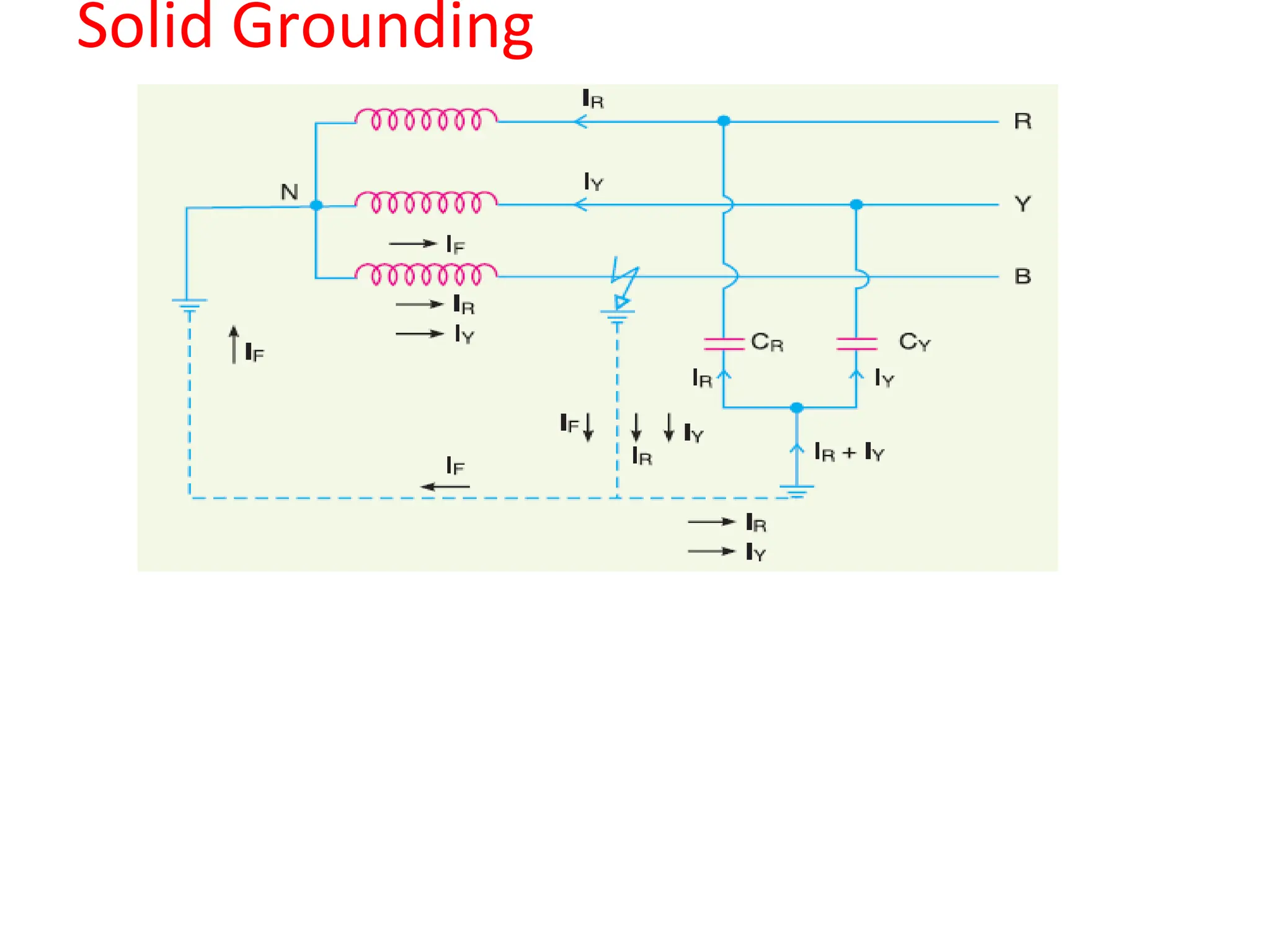
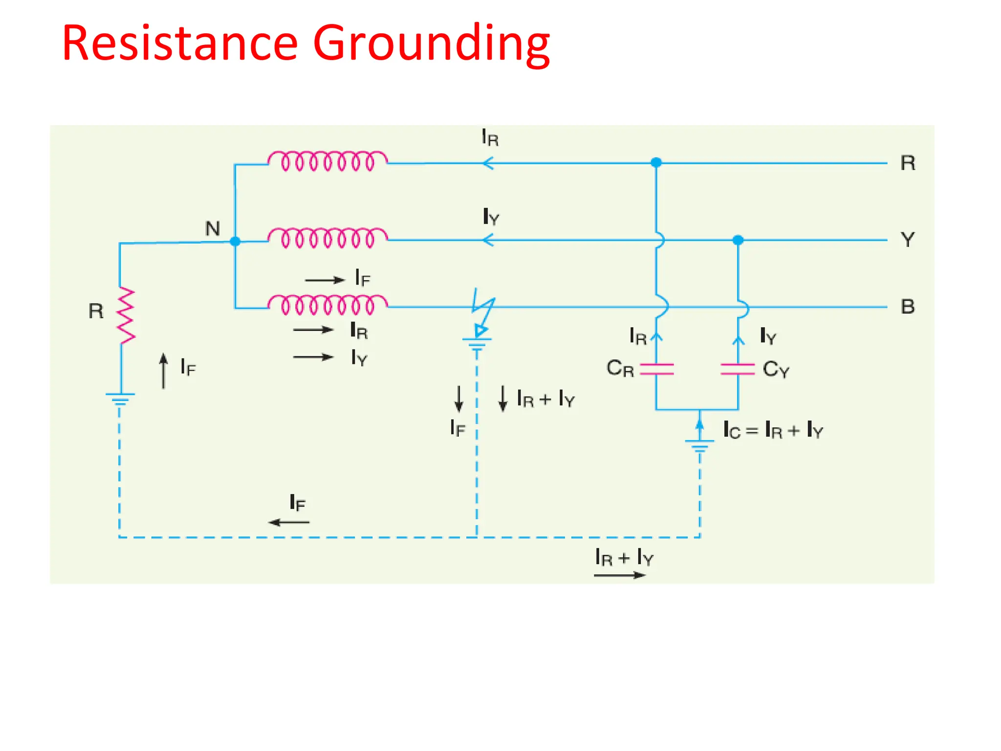
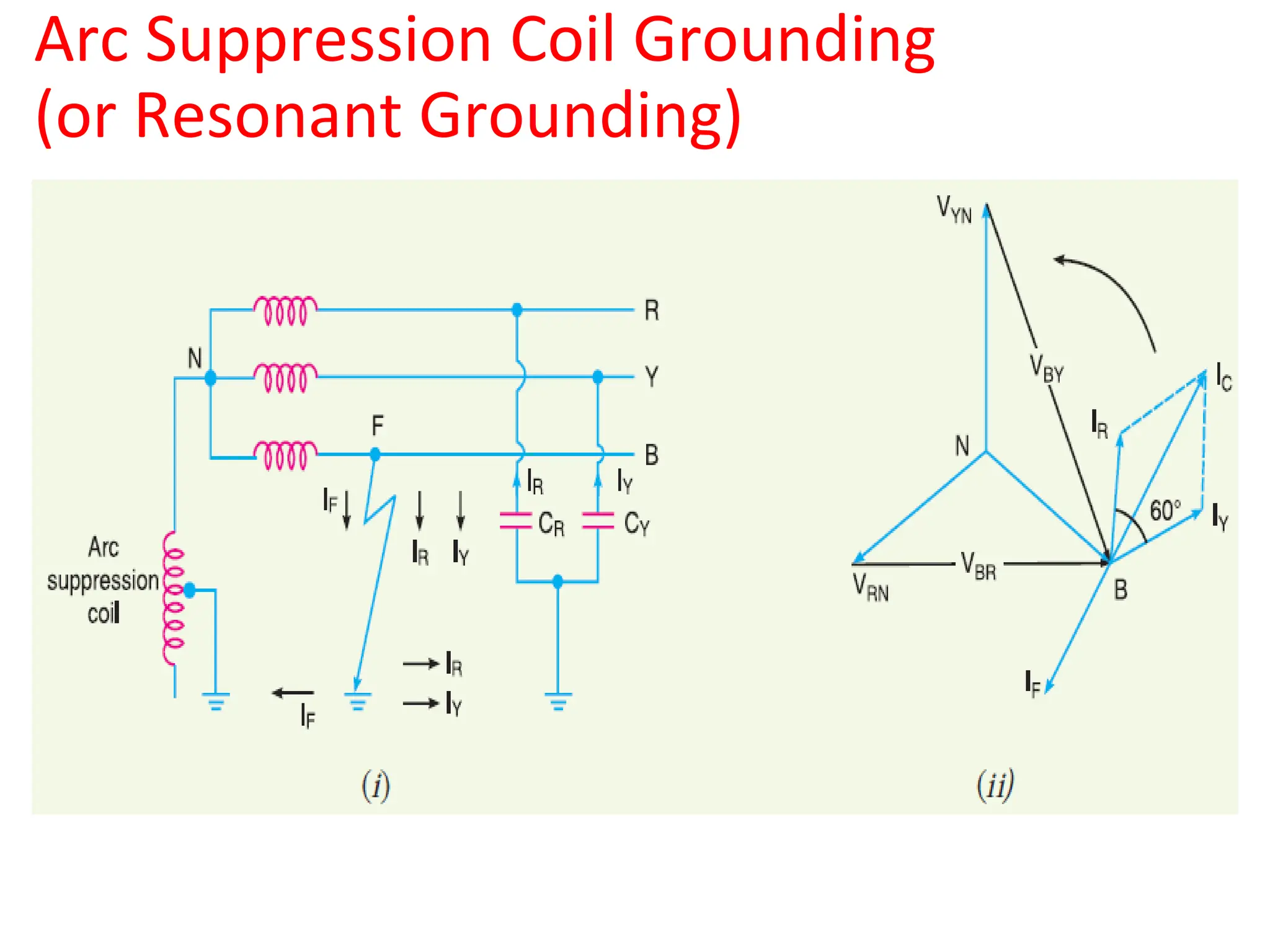
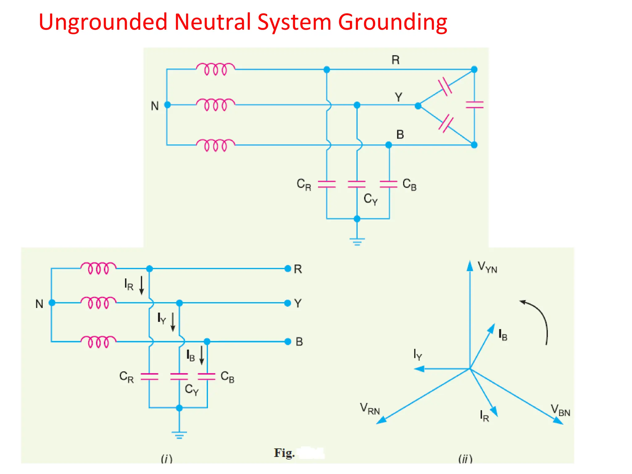
Circuit behavior under single line to ground-fault.
• The capacitive currents IR and IY flow through the lines R and Y respectively.
The voltages driving IR and IY are VBR and VBY respectively. Note that VBR and
VBY are the line voltages [See Fig. (ii)]. The paths of IR and IY are essentially
capacitive. Therefore, IR leads VBR by 90° and IY leads VBY by 90° as shown in
Fig. (ii). The capacitive fault current IC in line B is the phasor sum of IR and IY .](https://image.slidesharecdn.com/ee3601unit-1-240513061814-e52b1064/75/Protection-and-Switchgear-for-Engineering-38-2048.jpg)