This document discusses power system protection schemes, including:
- Zones of protection with protective relays coordinated between zones
- Attributes of reliable, selective, and fast relaying
- Fault clearing times of relays and circuit breakers
- Protection of system components like feeders, transmission lines, transformers, generators
It provides examples of overcurrent protection design using time-graded and current-graded discrimination. Directional relays, differential protection, and power line carrier communication are also summarized.
Introduction to protective relaying and the characteristics of protection zones focusing on relay attributes such as reliability, selectivity, and speed.
Details on maximum and minimum fault currents, permissible overloads, and the fault clearing time for relays and circuit breakers.
Various schemes for protecting feeders, transformers, alternators, and motors, including current and time graded discrimination in radial systems.
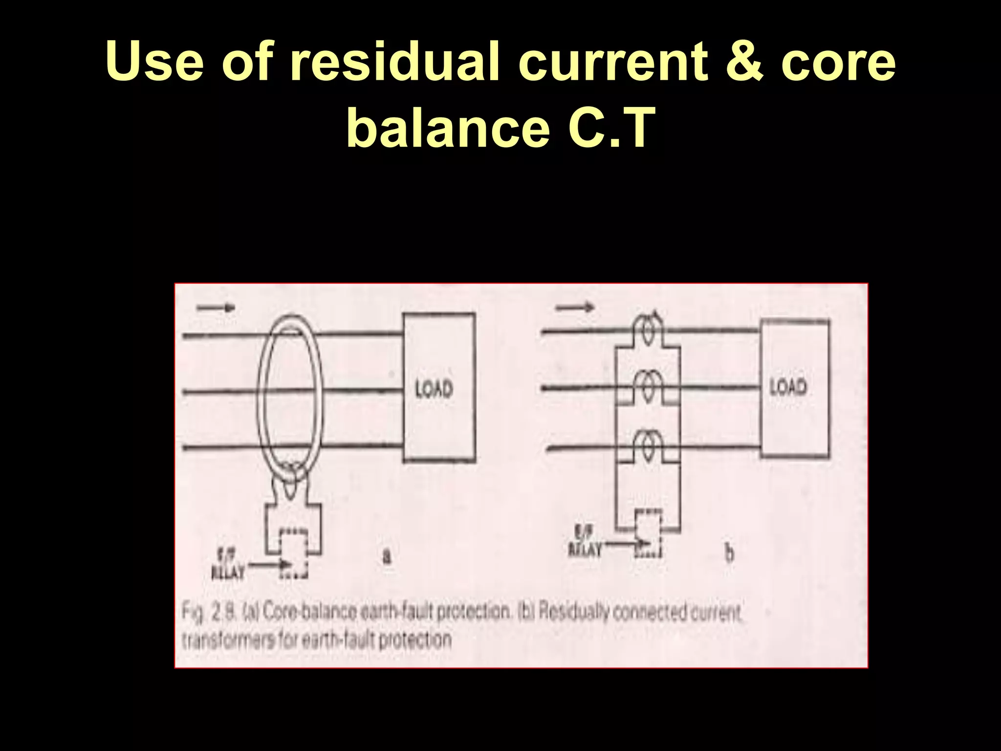
Use of directional relays and earth fault protection schemes including restricted and unrestricted methods.
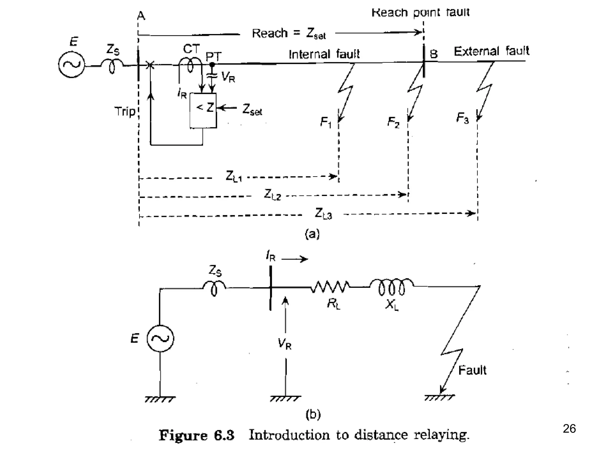
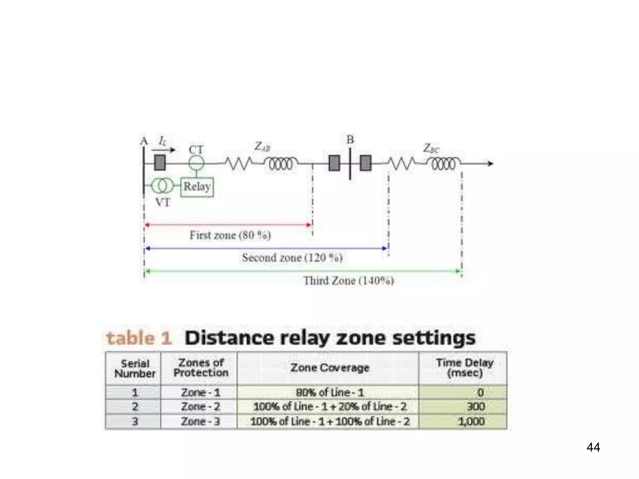
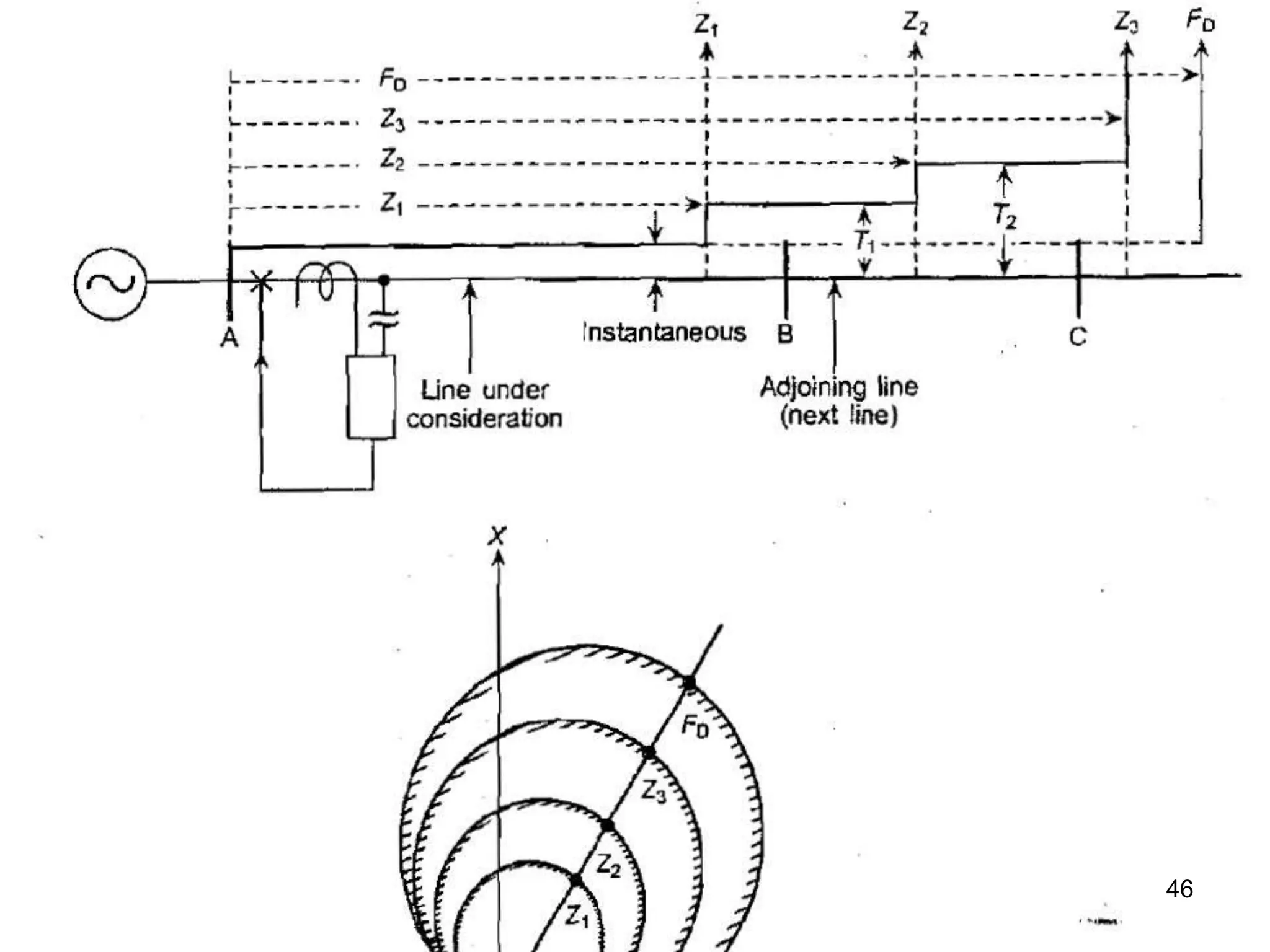
Challenges in the protection of transmission lines and the benefits of distance relaying approaches independent of source impedance.
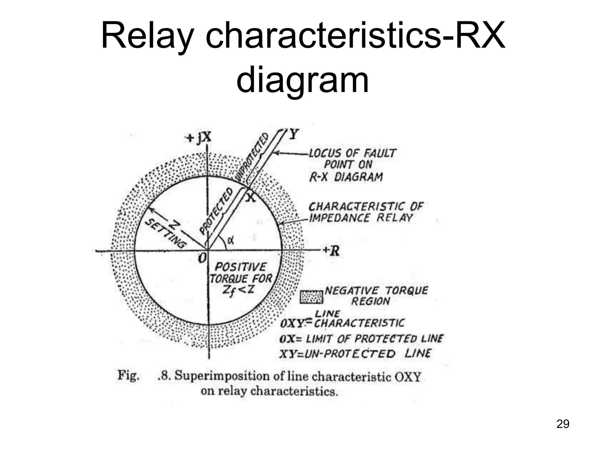
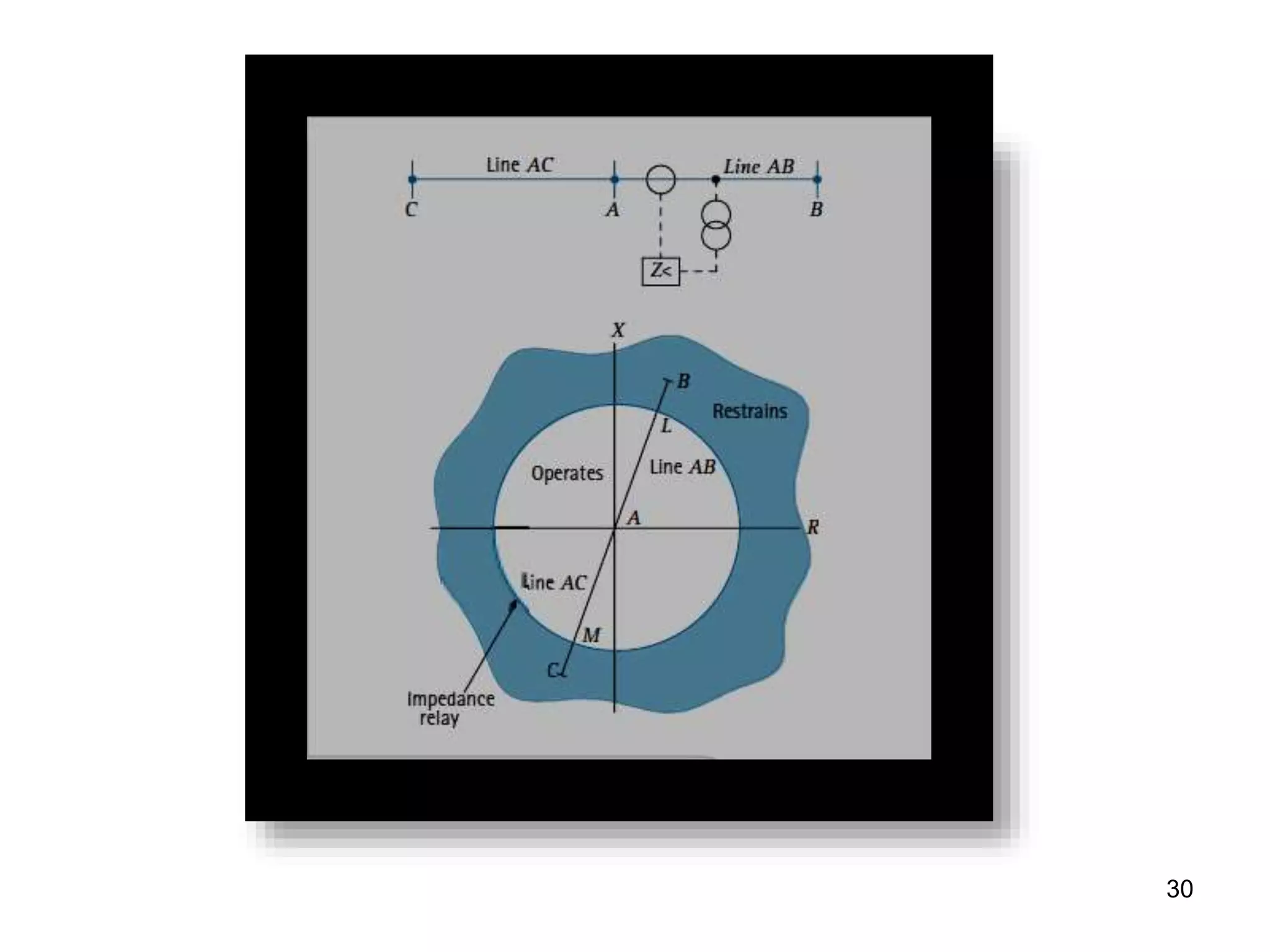
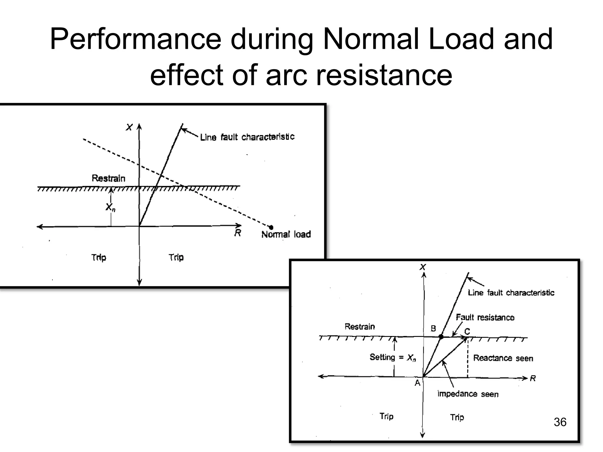
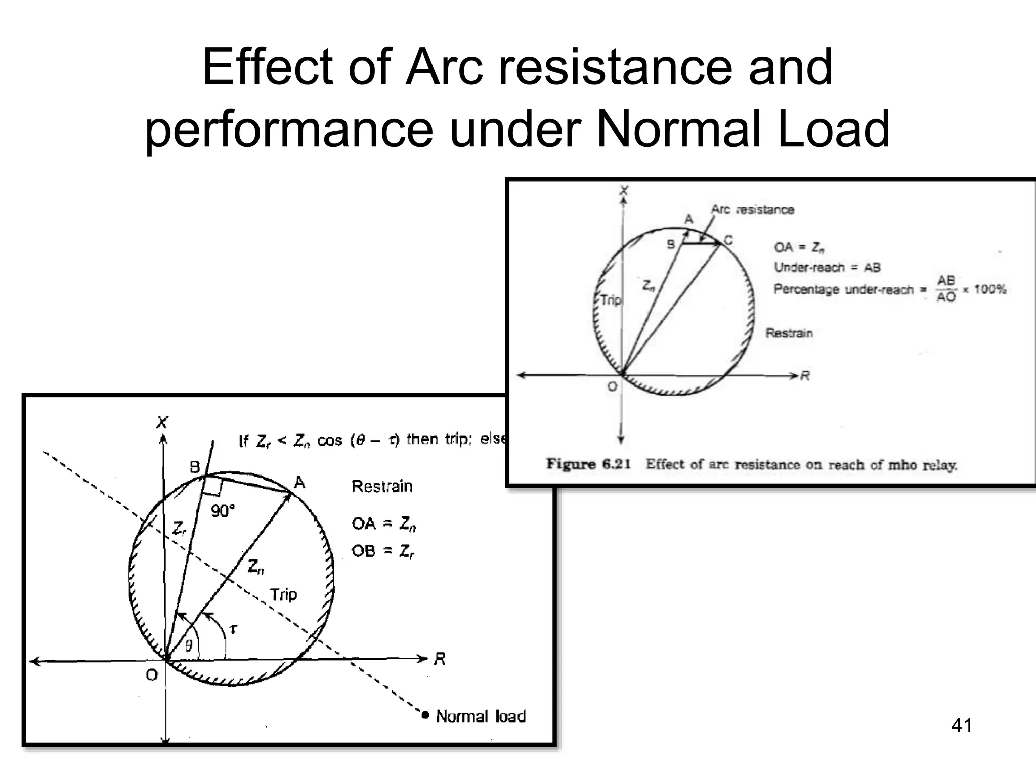
Various relay characteristics including impedance relay performance under normal load, arc resistance effects, and directional properties.
The importance of power line carrier communication in maintaining circuit breaker coordination for system stability.
Concept of unit protection and differential protection techniques to effectively respond to faults in power systems.
Challenges in transformer protection, including addressing inrush currents, CT ratio errors, and phase shift adjustments for YD transformers.
Calculation examples for determining appropriate CT ratios for transformers to ensure effective fault handling.
ZONE OF PROTECTION
•Power system is protected in zones, each
containing an alternator, a transformer, a
bus bar section or a transmission line.
Each zone has one or more protective
schemes, which are coordinated with
the overall protection with the following
characteristics
3.
ATTRIBUTES OF RELAYING
•RELIABILITY: security (avoid false operation) &
Dependability ( correct operation)
• SELECTIVITY: minimum disconnection & Maximum
continuity of service
• SPEED :
– Improved power system stability
– Decreased amount of damage incurred
– Less annoyance to electric power consumers
– Decreased likelihood of development of one type of fault into
other more severe type
– Rapid re-closure of circuit breakers to restore service to
customer.
Fault Clearing Time
•Relay operating Time
– High speed or instantaneous Relay: 1.0 to
2.0 cycles i.e., 0.02 to 0.04 sec.
• Circuit Breaker clearing Time:
– High speed C.Bs: 2.5 to 3.0 cycles i.e. 0.05
to 0.06 sec.
• Total clearing time = relay operating time+
circuit breaker clearing time
– Total clearing time may be between 0.07 to
0.1 sec.
6.
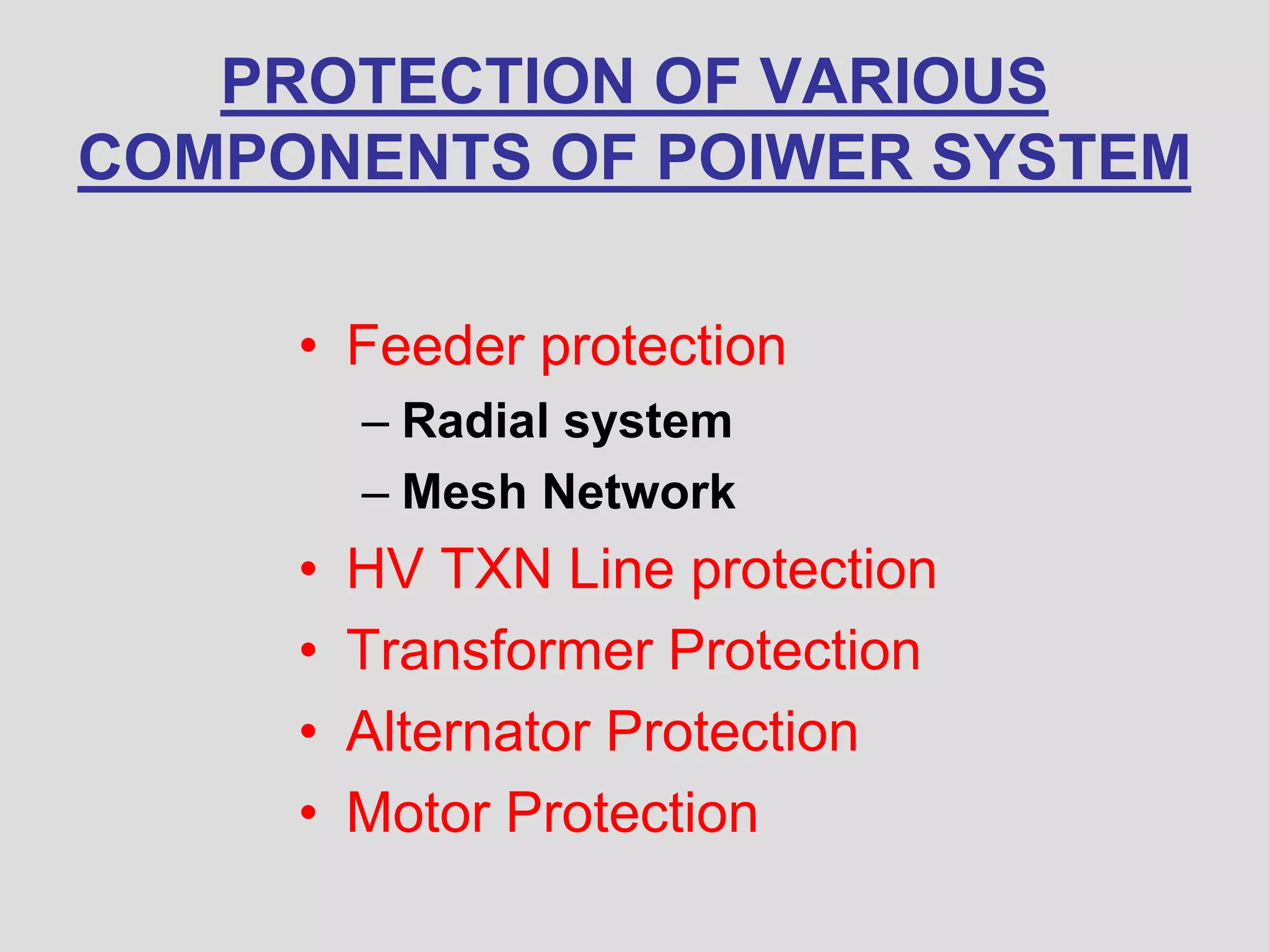
PROTECTION OF VARIOUS
COMPONENTSOF POIWER SYSTEM
• Feeder protection
– Radial system
– Mesh Network
• HV TXN Line protection
• Transformer Protection
• Alternator Protection
• Motor Protection
Criteria for overcurrent
protection of radial feeder
• The relay at the far end is operated in the shortest time as it does
not have to give back up to any other relay. Upstream relays
(moving back to source side) are time graded with about 0.3 second
delays. Definite time relays can be used where source impedance is
large as compared to the line impedance i.e., small variation of
current for near and far end faults.
• Inverse time (IDMT) relays can be used if lines are long and fault
level is much smaller at the far end fault than it is for source end
fault.
• Very or extremely inverse time can be selected where the line
impedance is high as compared to source impedance or in case
where coordination with fusses or re-closure is necessary.
11.
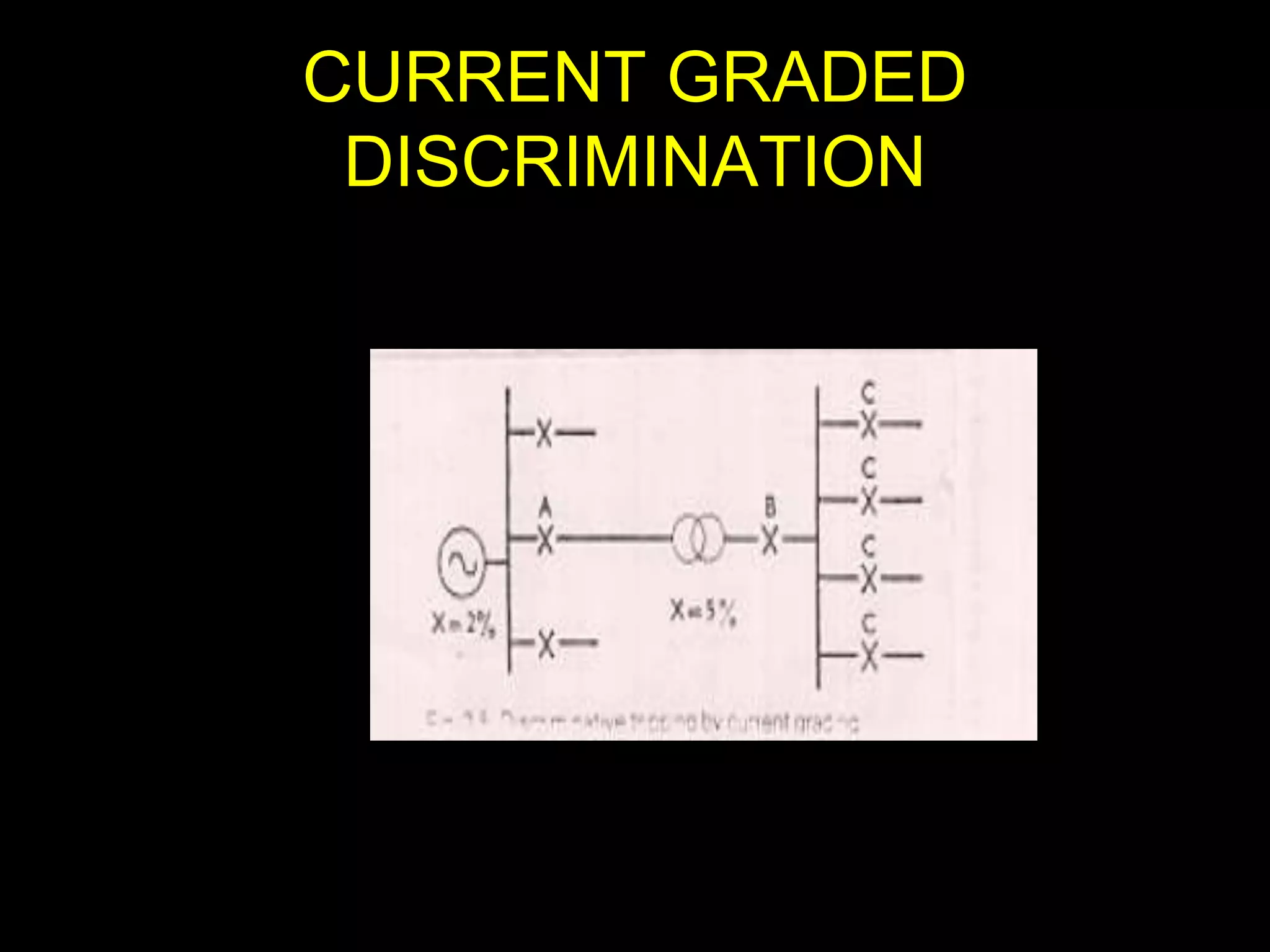
Feeder Protection byIDMT relay
• Both current graded & time graded
discrimination can be implemented
• Requires adjustment of PS and TMS
• Coordination delay time (C.D.T)= 0.3 or
0.5 seconds
12.
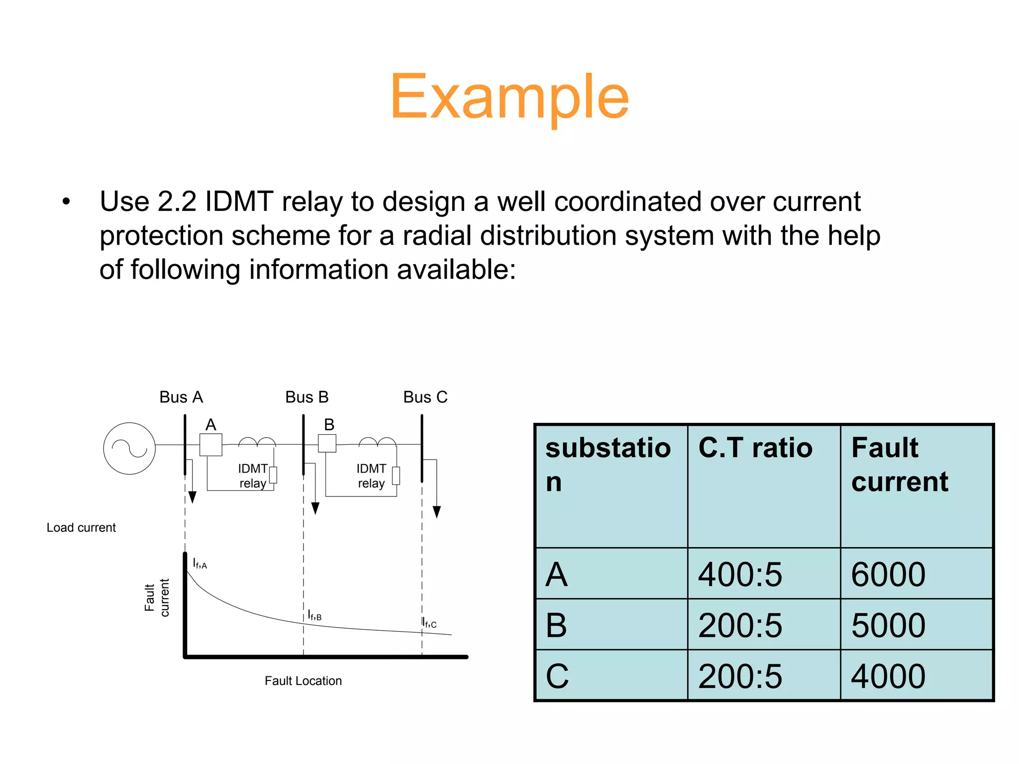
Example
• Use 2.2IDMT relay to design a well coordinated over current
protection scheme for a radial distribution system with the help
of following information available:
substatio
n
C.T ratio Fault
current
A 400:5 6000
B 200:5 5000
C 200:5 4000
Bus A Bus B Bus C
Load current
IDMT
relay
IDMT
relay
Fault
current
Fault Location
A B
If,A
If,B
If,C
13.
Bus A BusB Bus C
Load current
IDMT
relay
IDMT
relay
Fault
current
Fault Location
A B
If,A
If,B
If,C
14.
• Start relaysettings for the substation C farthest from the source
• set Relay B for back up protection for Rc
• Use CDT=0.5 seconds
• Check operating time of RB for the plug setting done in the preceding
step for a fault at substation B.
• Set PS and TMS of RA for backup of RB; using the CDT=0.5 seconds
• Check RA operating time for a fault at sub station A
Fault location RA
PS=125%
TMs=37.9%
RB
PS=125%
TMs=29%%
RC
PS=100%
TMs=10%
C - 0.72s 0.22s
B 1.138s 0.638s -
A 0.985s - -
Problems with transmission
linesprotection
• System configuration changes continuously
• More load added time to time
• Outages of T.L and/or generating units are
frequent.
• Due to complex meshed network and
interconnections, various loops exist in the
system. Hence selectivity can not be achieved
through simple over current relays
23.
Reach of overcurrent relay
• Reach of over current
relay depends on:
– type of fault
– Generation level or source
impedance value
23
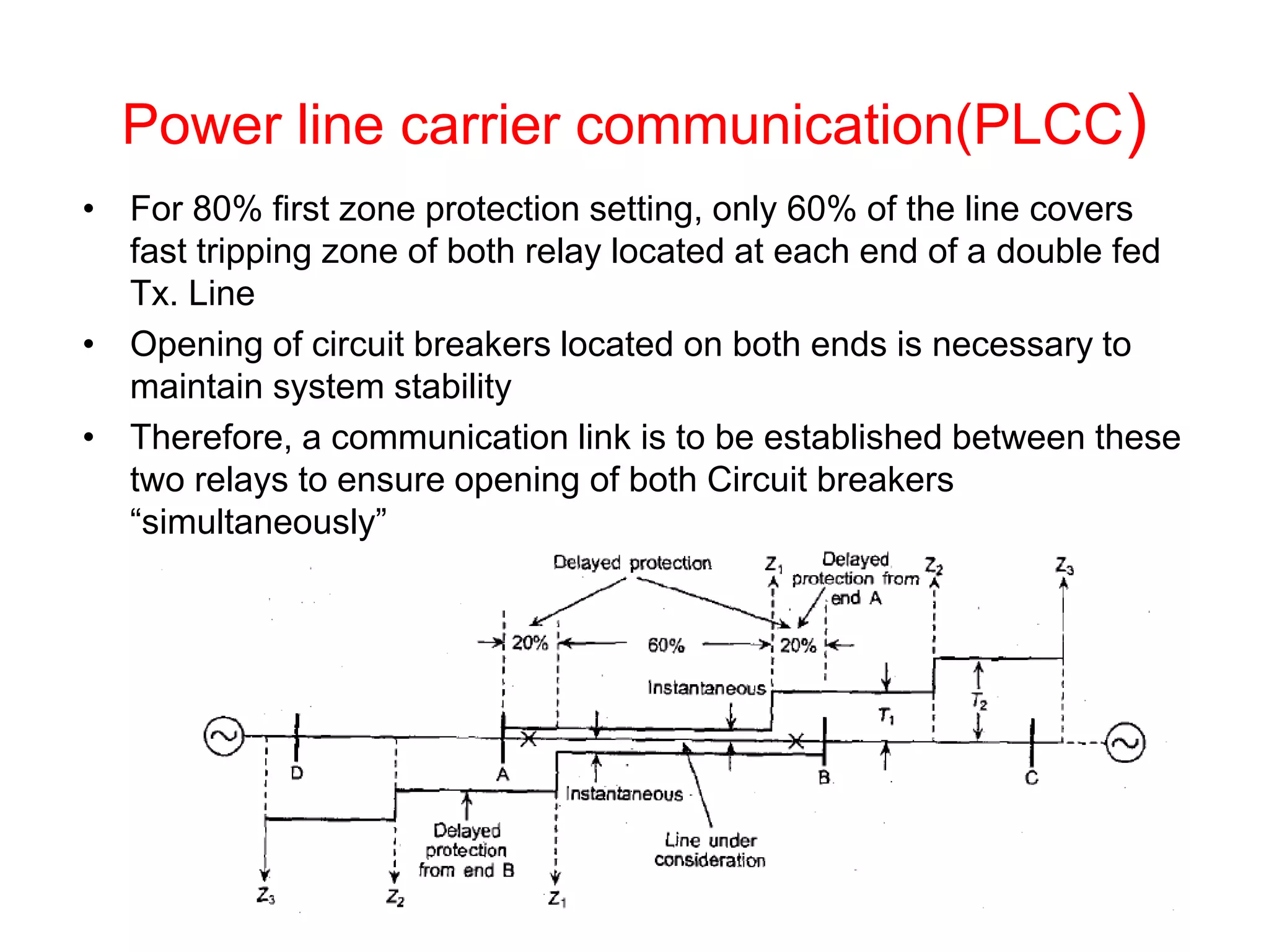
Power line carriercommunication(PLCC)
• For 80% first zone protection setting, only 60% of the line covers
fast tripping zone of both relay located at each end of a double fed
Tx. Line
• Opening of circuit breakers located on both ends is necessary to
maintain system stability
• Therefore, a communication link is to be established between these
two relays to ensure opening of both Circuit breakers
“simultaneously”
50.
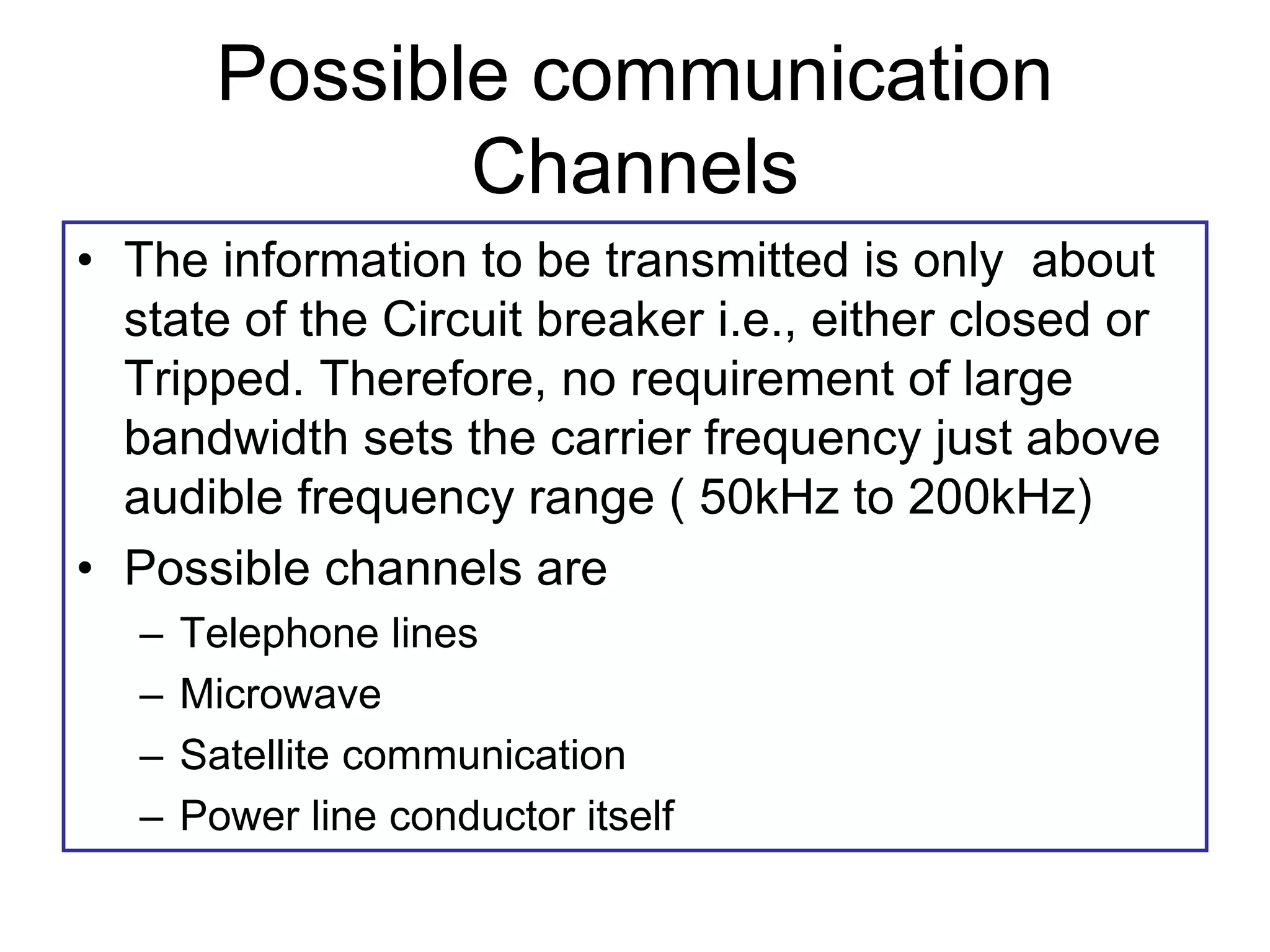
Possible communication
Channels
• Theinformation to be transmitted is only about
state of the Circuit breaker i.e., either closed or
Tripped. Therefore, no requirement of large
bandwidth sets the carrier frequency just above
audible frequency range ( 50kHz to 200kHz)
• Possible channels are
– Telephone lines
– Microwave
– Satellite communication
– Power line conductor itself
51.
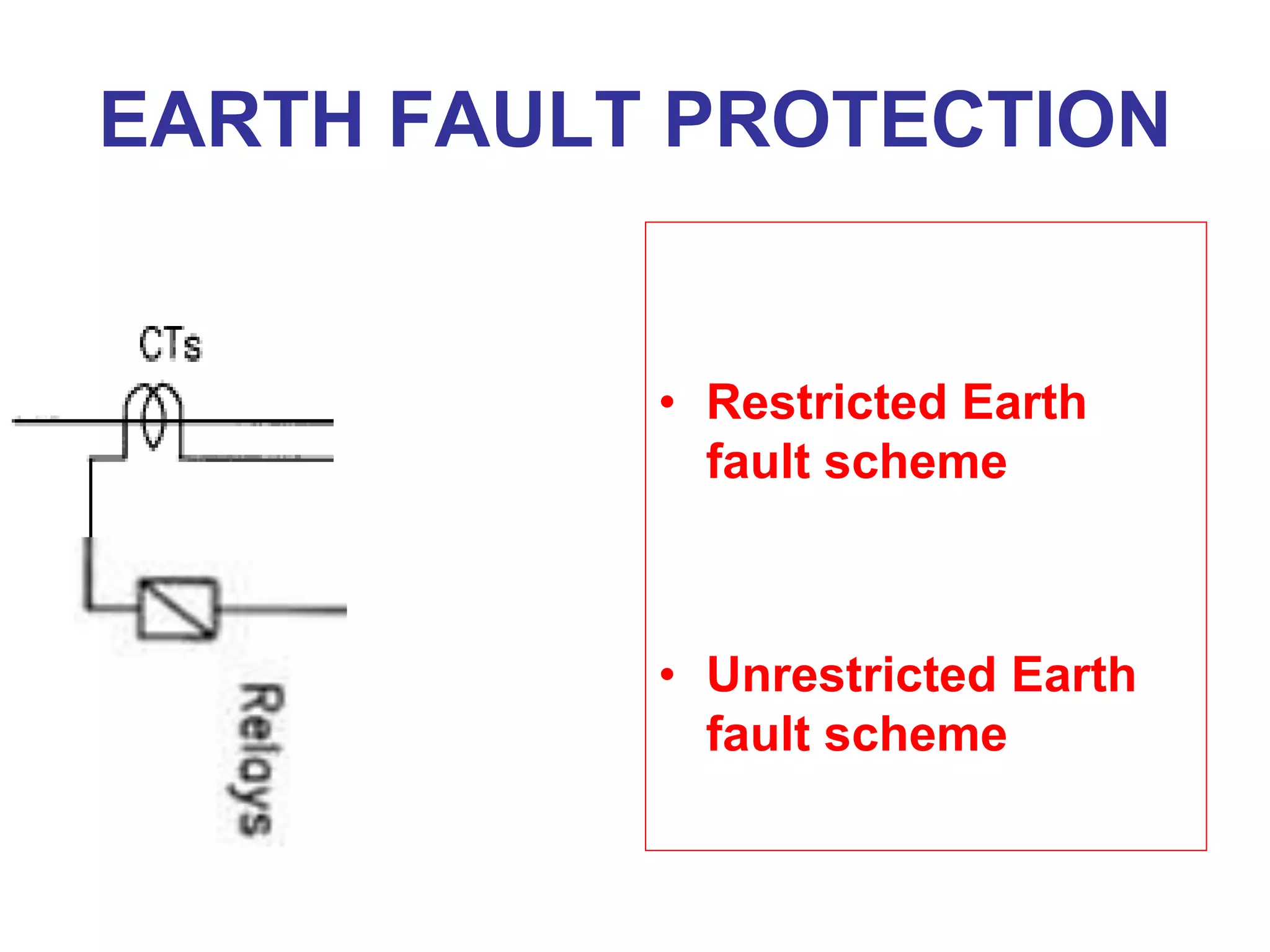
Unit Protection
• Gradedover current schemes drawbacks
– Satisfactory grading can not always be
arranged for complex network
– Setting may cause greater tripping times at
point in the system making protection
insufficient for excessive disturbance
• Concept of unit protection
– Where sections of the power system are
protected as a complete unit without
reference to other parts
52.
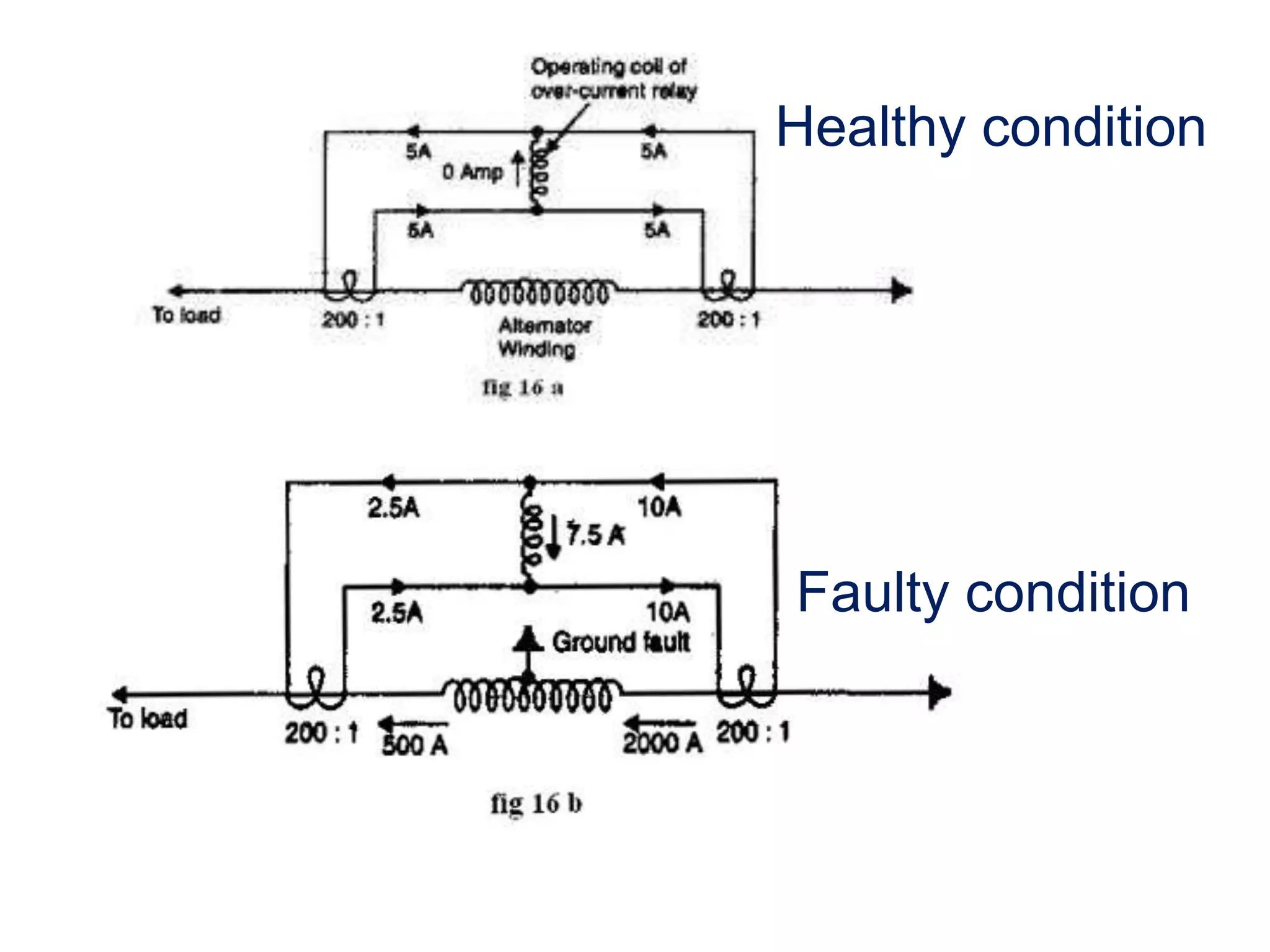
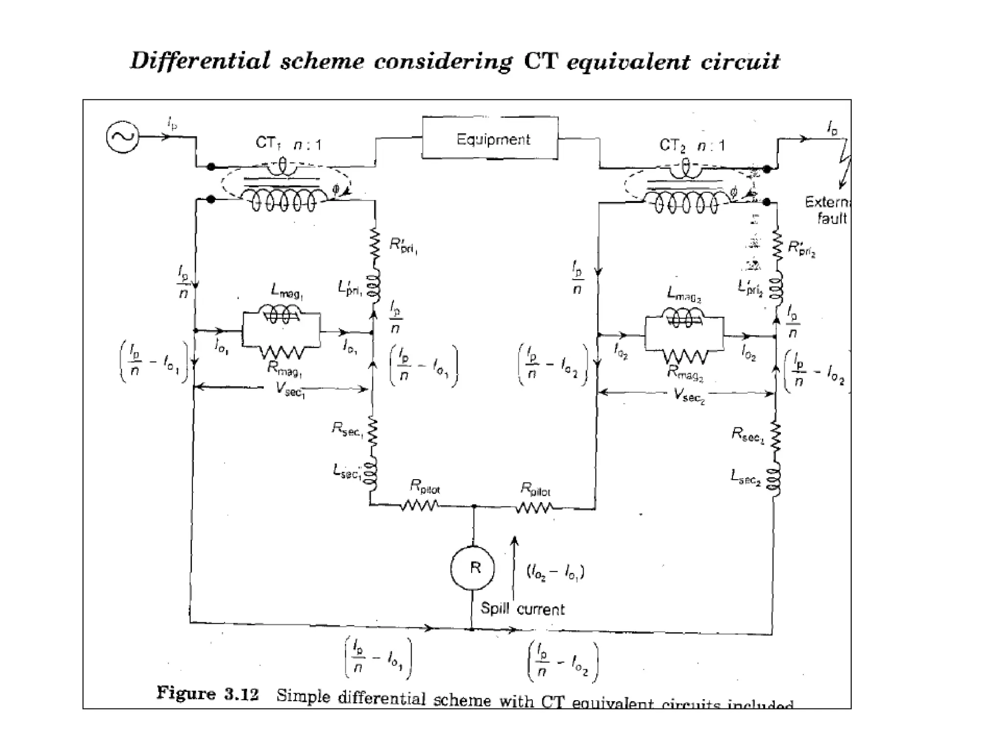
Example : Differentialprotection
• Works on difference between incoming and
outgoing currents
Pilot wires
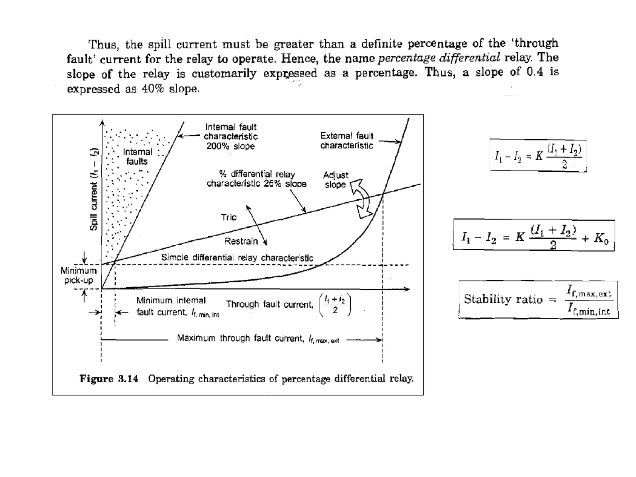
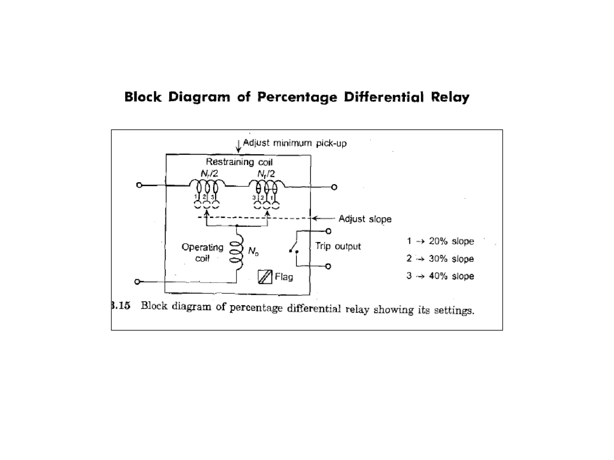
Requirements for differentialscheme
• Current magnitude seen by the relay on both sides should be equal
and in phase
• Relay must not trip for external or through faults
– Because of CT mismatch of characteristics, relay can mal-operate for external
fault as well.
– Therefore a restraint coil is used in addition to operating coil.
– Relay characteristics are changed to percent differential characteristics.
Difficulties with transformerprotection
• No load transformer
Switching transients
(inrush current) may be
differentiated from fault current by
measuring harmonics contents,(2nd
harmonic). Relay false operation is
blocked by harmonic restraint
• C.T ratio error is prominent for
through faults because of CTs
saturation at different level. Percent
bias coil is to be used
• Phase shift in YD
transformers is addressed by
proper connections of CTs on both
sides
Requirements:
• C.Ts secondaryline currents ( or current in
pilot wires) as seen by the relay should be
in phase
• C.Ts ratio must be adjusted so that current
seen by the relay should be equal in
magnitude under normal condition
Ex 14.7
• A3-phase transformer rated
for 33kV/6.6kV is connected
star-delta and the protecting
current transformer on the LV
side have a ratio of 400:5.
determine the ratio of the CT
on HV side
• A 3 phase , 200 kVA 110.4 kV,
DY transformer has CTs on
0.4 kV side a turns ratio of
500:5. what should be the CT
ratio on HV side of the
transformer? Also determine
the out of balance current
when a fault of 750A of the
following type occurs on LV
side: a) Earth fault within
protection zone and b) earth
fault outside the zone