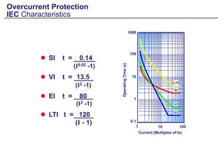
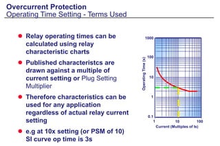
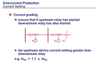
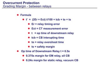
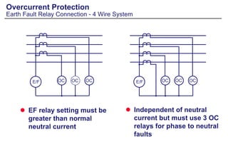
Application of Non-Directional Overcurrent
and Earthfault Protection
Non-Directional Overcurrent and Earth
Fault Protection
Overcurrent Protection
Purpose of Protection
 Detect abnormal conditions
 Isolate faulty part of the system
 Speed
 Fast operation to minimise damage and danger
 Discrimination
 Isolate only the faulty section
 Dependability / reliability
 Security / stability
 Cost of protection / against cost of potential hazards
Overcurrent Protection
Co-ordination
 Co-ordinate protection so that relay nearest to
fault operates first
 Minimise system disruption due to the fault
F1 F2
F3
F3
F2
F1
Fuses
Overcurrent Protection
Fuses
 Simple
 Can provide very fast fault clearance
 <10ms for large current
 Limit fault energy
Pre Arc Time
Arcing Time
Prospective Fault Current
Total
Operating
Time
t
Overcurrent Protection
Fuses - disadvantages
 Problematic co-ordination
 IFA approx 2 x IFB
 Limited sensitivity to earth faults
 Single phasing
 Fixed characteristic
 Need replacing following fault clearance
Fuse A Fuse B
Tripping Methods
Overcurrent Protection
Direct Acting AC Trip
 AC series trip
 common for electromechanical O/C relays
51
IF
Trip Coil
Overcurrent Protection
Direct Acting AC Trip
 Capacitor discharge trip
 used with static relays where no secure DC
supply is available
IF'
Sensitive
Trip
Coil
IF
51
+
-
Overcurrent Protection
DC Shunt Trip
 Requires secure DC auxiliary
 No trip if DC fails
IF'
IF
DC
BATTERY
SHUNT
TRIP COIL
51
Overcurrent Protection
Principles
 Operating Speed
 Instantaneous
 Time delayed
 Discrimination
 Current setting
 Time setting
 Current and time
 Cost
 Generally cheapest form of protection relay
IF1
IF1
IF2
Overcurrent Protection
Instantaneous Relays
 Current settings chosen so that relay closest to
fault operates
 Problem
 Relies on there being a difference in fault level
between the two relay locations
 Cannot discriminate if IF1 = IF2
50
B
50
A
IF1
IF2
Overcurrent Protection
Definite (Independent) Time Relays
TOP
TIME
IS Applied Current
(Relay Current Setting)
Overcurrent Protection
Definite (Independent) Time Relays
 Operating time is independent of current
 Relay closest to fault has shortest operating time
 Problem
 Longest operating time is at the source where
fault level is highest
51
0.9 sec 0.5 sec
51
Overcurrent Protection
IDMT
 Inverse Definite Minimum Time characteristic
TIME
Applied Current
(Relay Current Setting)
IS
Overcurrent Protection
Disc Type O/C Relays
 Current setting via plug bridge
 Time multiplier setting via disc
movement
 Single characteristic
 Consider 2 ph & EF or 3 ph
plus additional EF relay
Overcurrent Protection
Static Relay
 Electronic, multi characteristic
 Fine settings, wide range
 Integral instantaneous elements
Overcurrent Protection
Numerical Relay
 Multiple characteristics and stages
 Current settings in primary or secondary
values
 Additional protection elements
Current
Time
I>1
I>2
I>3
I>4
Co-ordination
Overcurrent Protection
Co-ordination Principle
 Relay closest to fault
must operate first
 Other relays must have
adequate additional
operating time to
prevent them operating
 Current setting chosen
to allow FLC
 Consider worst case
conditions, operating
modes and current
flows
T
IS1
IS2
Maximum
Fault
Level
I
R2
R1
IF1
Overcurrent Protection
Co-ordination Example
C A
B
0.01
0.1
1
10
Operating
time
(s)
Current (A) FLB FLC FLD
E
D
C
B
D
E
Overcurrent Protection
IEC Characteristics
 SI t = 0.14
(I0.02 -1)
 VI t = 13.5
(I2 -1)
 EI t = 80
(I2 -1)
 LTI t = 120
(I - 1)
Current (Multiples of Is)
0.1
1
10
100
1000
1 100
10
Operating
Time
(s)
VI
EI
SI
LTI
Overcurrent Protection
Operating Time Setting - Terms Used
 Relay operating times can be
calculated using relay
characteristic charts
 Published characteristcs are
drawn against a multiple of
current setting or Plug Setting
Multiplier
 Therefore characteristics can be
used for any application
regardless of actual relay current
setting
 e.g at 10x setting (or PSM of 10)
SI curve op time is 3s
Current (Multiples of Is)
0.1
1
10
100
1000
1 100
10
Operating
Time
(s)
Overcurrent Protection
Current Setting
 Set just above full load current
 allow 10% tolerance
 Allow relay to reset if fault is cleared by
downstream device
 consider pickup/drop off ratio (reset ratio)
 relay must fully reset with full load current
flowing
 PU/DO for static/numerical = 95%
 PU/DO for EM relay = 90%
 e.g for numerical relay, Is = 1.1 x IFL/0.95
Overcurrent Protection
Current Setting
 Current grading
 ensure that if upstream relay has started
downstream relay has also started
 Set upstream device current setting greater than
downstream relay
e.g. IsR1 = 1.1 x IsR2
R1 R2
IF1
Overcurrent Protection
Grading Margin
 Operating time difference between two devices to
ensure that downstream device will clear fault before
upstream device trips
 Must include
 breaker opening time
 allowance for errors
 relay overshoot time
 safety margin
GRADING
MARGIN
Overcurrent Protection
Grading Margin - between relays
 Traditional
 breaker op time - 0.1
 relay overshoot - 0.05
 allow. For errors - 0.15
 safety margin - 0.1
 Total 0.4s
 Calculate using formula
R2
R1
Overcurrent Protection
Grading Margin - between relays
 Formula
 t’ = (2Er + Ect) t/100 + tcb + to + ts
 Er = relay timing error
 Ect = CT measurement error
 t = op time of downstream relay
 tcb = CB interupting time
 to = relay overshoot time
 ts = safety margin
 Op time of Downstream Relay t = 0.5s
 0.375s margin for EM relay, oil CB
 0.24s margin for static relay, vacuum CB
Overcurrent Protection
Grading Margin - relay with fuse
 Grading Margin = 0.4Tf + 0.15s over whole characteristic
 Assume fuse minimum operating time = 0.01s
 Use EI or VI curve to grade with fuse
 Current setting of relay should be 3-4 x rating of fuse to
ensure co-ordination
Overcurrent Protection
Grading Margin - relay with upstream fuse
 1.175Tr + 0.1 + 0.1 = 0.6Tf
or
 Tf = 2Tr + 0.33s
Allowance for CT
and relay error
CB Safety margin Allowance for fuse
error (fast)
Tf
Tr
IFMAX
Overcurrent Protection
Time Multiplier Setting
 Used to adjust the operating
time of an inverse
characteristic
 Not a time setting but a
multiplier
 Calculate TMS to give
desired operating time in
accordance with the grading
margin
Current (Multiples of Is)
0.1
1
10
100
1 100
10
Operating
Time
(s)
Overcurrent Protection
Time Multiplier Setting - Calculation
 Calculate relay operating time required, Treq
 consider grading margin
 fault level
 Calculate op time of inverse characteristic
with TMS = 1, T1
 TMS = Treq /T1
Overcurrent Protection
Co-ordination - Procedure
 Calculate required operating current
 Calculate required grading margin
 Calculate required operating time
 Select characteristic
 Calculate required TMS
 Draw characteristic, check grading over whole
curve
Grading curves should be drawn to a common
voltage base to aid comparison
Overcurrent Protection
Co-ordination Example
 Grade relay B with relay A
 Co-ordinate at max fault level seen by both relays =
1400A
 Assume grading margin of 0.4s
Is = 5 Amp; TMS = 0.05, SI
I
FMAX
= 1400 Amp
B A
200/5 100/5
Is = 5 Amp
Overcurrent Protection
Co-ordination Example
 Relay B is set to 200A primary, 5A secondary
 Relay A set to 100A  If (1400A) = PSM of 14
relay A OP time = t = 0.14 x TMS = 0.14 x 0.05 = 0.13
(I0.02 -1) (140.02 -1)
 Relay B Op time = 0.13 + grading margin = 0.13 + 0.4 = 0.53s
 Relay A uses SI curve so relay B should also use SI curve
Is = 5 Amp; TMS = 0.05, SI
I
FMAX
= 1400 Amp
B A
200/5 100/5
Is = 5 Amp
Overcurrent Protection
Co-ordination Example
 Relay B Op time = 0.13 + grading margin = 0.13 + 0.4 = 0.53s
 Relay A uses SI curve so relay B should also use SI curve
 Relay B set to 200A  If (1400A) = PSM of 7
relay B OP time TMS = 1 = 0.14 x TMS = 0.14 = 3.52s
(I0.02 -1) (70.02 -1)
 Required TMS = Required Op time = 0.53 = 0.15
Op time TMS=1 3.52
 Set relay B to 200A, TMS = 0.15, SI
Is = 5 Amp; TMS = 0.05, SI
IFMAX
= 1400 Amp
B A
200/5 100/5
Is = 5 Amp
Overcurrent Protection
LV Protection Co-ordination
ZA2118B
Relay 1
Relay 2
Relay 3
Relay 4
Fuse
1
2
3
4
F
350MVA
4 4
3 3
2
F
11kV
MCGG CB
ACB CTZ61 (Open)
CTZ61
ACB
MCCB
27MVA
20MVA
Load
Fuse
2 x 1.5MVA
11kV/433V
5.1%
K
1
Overcurrent Protection
LV Protection Co-ordination
ZA2119
1000S
100S
10S
1.0S
0.1S
0.01S
0. 1kA 10kA 1000kA
TX damage
Very
inverse
Overcurrent Protection
LV Protection Co-ordination
ZA2120C
Relay 1
Relay 2
Relay 3
Relay 4
Fuse
1
2
3
4
F
350MVA
4 4
3 3
2
1
F
11kV
KCGG 142 CB
ACB (Open)
KCEG 142
ACB
MCCB
27MVA
20MVA
Load
Fuse
2 x 1.5MVA
11kV/433V
5.1%
K
Overcurrent Protection
LV Protection Co-ordination
ZA2121
1000S
100S
10S
1.0S
0.1S
0.01S
0. 1kA 10kA 1000kA
TX damage
Long time
inverse
ZA2135
R3
R2
R1
Block t >
I > Start
IF2
IF1
M (Transient backfeed ?)
Graded
protection
Blocked
protection
Overcurrent Protection
Blocked OC Schemes
Use of High Sets
 Fast clearance of faults
 ensure good operation factor, If >> Is (5 x ?)
 Current setting must be co-ordinated to prevent
overtripping
 Used to provide fast tripping on HV side of transformers
 Used on feeders with Auto Reclose, prevents transient
faults becoming permanent
 AR ensures healthy feeders are re-energised
 Consider operation due to DC offset - transient
overreach
Overcurrent Protection
Instantaneous Protection
 Set HV inst 130% IfLV
 Stable for inrush
 No operation for LV fault
 Fast operation for HV
fault
 Reduces op times
required of upstream
relays
HV2 LV
HV1
HV2
LV
TIME
CURRENT
HV1
IF(LV) IF(HV)
1.3IF(LV)
Overcurrent Protection
Instantaneous OC on Transformer Feeders
Earthfault Protection
 Earth fault current may be limited
 Sensitivity and speed requirements may not be met by
overcurrent relays
 Use dedicated EF protection relays
 Connect to measure residual (zero sequence) current
 Can be set to values less than full load current
 Co-ordinate as for OC elements
 May not be possible to provide co-ordination with
fuses
Overcurrent Protection
Earth Fault Protection
 Combined with OC relays
E/F OC OC OC E/F OC OC
 Economise using 2x OC
relays
Overcurrent Protection
Earth Fault Relay Connection - 3 Wire System
 EF relay setting must be
greater than normal
neutral current
 Independent of neutral
current but must use 3 OC
relays for phase to neutral
faults
E/F OC OC OC E/F OC OC OC
Overcurrent Protection
Earth Fault Relay Connection - 4 Wire System
 Solid earth
 30% Ifull load
adequate
 Resistance earth
 setting w.r.t earth fault
level
 special considerations
for impedance earthing
- directional?
Overcurrent Protection
Earth Fault Relays Current Setting
 Settings down to
0.2% possible
 Isolated/high
impedance earth networks
 For low settings cannot use residual connection, use
dedicated CT
 Advisable to use core balance CT
 CT ratio related to earth fault current not line current
 Relays tuned to system frequency to reject 3rd
harmonic
B
C
E/F
A
Overcurrent Protection
Sensitive Earth Fault Relays
 Need to take care with core
balance CT and armoured
cables
 Sheath acts as earth return
path
 Must account for earth current
path in connections - insulate
cable gland
NO OPERATION OPERATION
CABLE
BOX
CABLE GLAND
CABLE GLAND/SHEATH
EARTH CONNECTION
E/F
Overcurrent Protection
Core Balance CT Connections

03-Non-Dir. Overcurrent.ppt

  • 2.
    Application of Non-DirectionalOvercurrent and Earthfault Protection
  • 3.
    Non-Directional Overcurrent andEarth Fault Protection
  • 4.
    Overcurrent Protection Purpose ofProtection  Detect abnormal conditions  Isolate faulty part of the system  Speed  Fast operation to minimise damage and danger  Discrimination  Isolate only the faulty section  Dependability / reliability  Security / stability  Cost of protection / against cost of potential hazards
  • 5.
    Overcurrent Protection Co-ordination  Co-ordinateprotection so that relay nearest to fault operates first  Minimise system disruption due to the fault F1 F2 F3 F3 F2 F1
  • 6.
  • 7.
    Overcurrent Protection Fuses  Simple Can provide very fast fault clearance  <10ms for large current  Limit fault energy Pre Arc Time Arcing Time Prospective Fault Current Total Operating Time t
  • 8.
    Overcurrent Protection Fuses -disadvantages  Problematic co-ordination  IFA approx 2 x IFB  Limited sensitivity to earth faults  Single phasing  Fixed characteristic  Need replacing following fault clearance Fuse A Fuse B
  • 9.
  • 10.
    Overcurrent Protection Direct ActingAC Trip  AC series trip  common for electromechanical O/C relays 51 IF Trip Coil
  • 11.
    Overcurrent Protection Direct ActingAC Trip  Capacitor discharge trip  used with static relays where no secure DC supply is available IF' Sensitive Trip Coil IF 51 + -
  • 12.
    Overcurrent Protection DC ShuntTrip  Requires secure DC auxiliary  No trip if DC fails IF' IF DC BATTERY SHUNT TRIP COIL 51
  • 13.
  • 14.
    Overcurrent Protection Principles  OperatingSpeed  Instantaneous  Time delayed  Discrimination  Current setting  Time setting  Current and time  Cost  Generally cheapest form of protection relay
  • 15.
    IF1 IF1 IF2 Overcurrent Protection Instantaneous Relays Current settings chosen so that relay closest to fault operates  Problem  Relies on there being a difference in fault level between the two relay locations  Cannot discriminate if IF1 = IF2 50 B 50 A IF1 IF2
  • 16.
    Overcurrent Protection Definite (Independent)Time Relays TOP TIME IS Applied Current (Relay Current Setting)
  • 17.
    Overcurrent Protection Definite (Independent)Time Relays  Operating time is independent of current  Relay closest to fault has shortest operating time  Problem  Longest operating time is at the source where fault level is highest 51 0.9 sec 0.5 sec 51
  • 18.
    Overcurrent Protection IDMT  InverseDefinite Minimum Time characteristic TIME Applied Current (Relay Current Setting) IS
  • 19.
    Overcurrent Protection Disc TypeO/C Relays  Current setting via plug bridge  Time multiplier setting via disc movement  Single characteristic  Consider 2 ph & EF or 3 ph plus additional EF relay
  • 20.
    Overcurrent Protection Static Relay Electronic, multi characteristic  Fine settings, wide range  Integral instantaneous elements
  • 21.
    Overcurrent Protection Numerical Relay Multiple characteristics and stages  Current settings in primary or secondary values  Additional protection elements Current Time I>1 I>2 I>3 I>4
  • 22.
  • 23.
    Overcurrent Protection Co-ordination Principle Relay closest to fault must operate first  Other relays must have adequate additional operating time to prevent them operating  Current setting chosen to allow FLC  Consider worst case conditions, operating modes and current flows T IS1 IS2 Maximum Fault Level I R2 R1 IF1
  • 24.
    Overcurrent Protection Co-ordination Example CA B 0.01 0.1 1 10 Operating time (s) Current (A) FLB FLC FLD E D C B D E
  • 25.
    Overcurrent Protection IEC Characteristics SI t = 0.14 (I0.02 -1)  VI t = 13.5 (I2 -1)  EI t = 80 (I2 -1)  LTI t = 120 (I - 1) Current (Multiples of Is) 0.1 1 10 100 1000 1 100 10 Operating Time (s) VI EI SI LTI
  • 26.
    Overcurrent Protection Operating TimeSetting - Terms Used  Relay operating times can be calculated using relay characteristic charts  Published characteristcs are drawn against a multiple of current setting or Plug Setting Multiplier  Therefore characteristics can be used for any application regardless of actual relay current setting  e.g at 10x setting (or PSM of 10) SI curve op time is 3s Current (Multiples of Is) 0.1 1 10 100 1000 1 100 10 Operating Time (s)
  • 27.
    Overcurrent Protection Current Setting Set just above full load current  allow 10% tolerance  Allow relay to reset if fault is cleared by downstream device  consider pickup/drop off ratio (reset ratio)  relay must fully reset with full load current flowing  PU/DO for static/numerical = 95%  PU/DO for EM relay = 90%  e.g for numerical relay, Is = 1.1 x IFL/0.95
  • 28.
    Overcurrent Protection Current Setting Current grading  ensure that if upstream relay has started downstream relay has also started  Set upstream device current setting greater than downstream relay e.g. IsR1 = 1.1 x IsR2 R1 R2 IF1
  • 29.
    Overcurrent Protection Grading Margin Operating time difference between two devices to ensure that downstream device will clear fault before upstream device trips  Must include  breaker opening time  allowance for errors  relay overshoot time  safety margin GRADING MARGIN
  • 30.
    Overcurrent Protection Grading Margin- between relays  Traditional  breaker op time - 0.1  relay overshoot - 0.05  allow. For errors - 0.15  safety margin - 0.1  Total 0.4s  Calculate using formula R2 R1
  • 31.
    Overcurrent Protection Grading Margin- between relays  Formula  t’ = (2Er + Ect) t/100 + tcb + to + ts  Er = relay timing error  Ect = CT measurement error  t = op time of downstream relay  tcb = CB interupting time  to = relay overshoot time  ts = safety margin  Op time of Downstream Relay t = 0.5s  0.375s margin for EM relay, oil CB  0.24s margin for static relay, vacuum CB
  • 32.
    Overcurrent Protection Grading Margin- relay with fuse  Grading Margin = 0.4Tf + 0.15s over whole characteristic  Assume fuse minimum operating time = 0.01s  Use EI or VI curve to grade with fuse  Current setting of relay should be 3-4 x rating of fuse to ensure co-ordination
  • 33.
    Overcurrent Protection Grading Margin- relay with upstream fuse  1.175Tr + 0.1 + 0.1 = 0.6Tf or  Tf = 2Tr + 0.33s Allowance for CT and relay error CB Safety margin Allowance for fuse error (fast) Tf Tr IFMAX
  • 34.
    Overcurrent Protection Time MultiplierSetting  Used to adjust the operating time of an inverse characteristic  Not a time setting but a multiplier  Calculate TMS to give desired operating time in accordance with the grading margin Current (Multiples of Is) 0.1 1 10 100 1 100 10 Operating Time (s)
  • 35.
    Overcurrent Protection Time MultiplierSetting - Calculation  Calculate relay operating time required, Treq  consider grading margin  fault level  Calculate op time of inverse characteristic with TMS = 1, T1  TMS = Treq /T1
  • 36.
    Overcurrent Protection Co-ordination -Procedure  Calculate required operating current  Calculate required grading margin  Calculate required operating time  Select characteristic  Calculate required TMS  Draw characteristic, check grading over whole curve Grading curves should be drawn to a common voltage base to aid comparison
  • 37.
    Overcurrent Protection Co-ordination Example Grade relay B with relay A  Co-ordinate at max fault level seen by both relays = 1400A  Assume grading margin of 0.4s Is = 5 Amp; TMS = 0.05, SI I FMAX = 1400 Amp B A 200/5 100/5 Is = 5 Amp
  • 38.
    Overcurrent Protection Co-ordination Example Relay B is set to 200A primary, 5A secondary  Relay A set to 100A  If (1400A) = PSM of 14 relay A OP time = t = 0.14 x TMS = 0.14 x 0.05 = 0.13 (I0.02 -1) (140.02 -1)  Relay B Op time = 0.13 + grading margin = 0.13 + 0.4 = 0.53s  Relay A uses SI curve so relay B should also use SI curve Is = 5 Amp; TMS = 0.05, SI I FMAX = 1400 Amp B A 200/5 100/5 Is = 5 Amp
  • 39.
    Overcurrent Protection Co-ordination Example Relay B Op time = 0.13 + grading margin = 0.13 + 0.4 = 0.53s  Relay A uses SI curve so relay B should also use SI curve  Relay B set to 200A  If (1400A) = PSM of 7 relay B OP time TMS = 1 = 0.14 x TMS = 0.14 = 3.52s (I0.02 -1) (70.02 -1)  Required TMS = Required Op time = 0.53 = 0.15 Op time TMS=1 3.52  Set relay B to 200A, TMS = 0.15, SI Is = 5 Amp; TMS = 0.05, SI IFMAX = 1400 Amp B A 200/5 100/5 Is = 5 Amp
  • 40.
    Overcurrent Protection LV ProtectionCo-ordination ZA2118B Relay 1 Relay 2 Relay 3 Relay 4 Fuse 1 2 3 4 F 350MVA 4 4 3 3 2 F 11kV MCGG CB ACB CTZ61 (Open) CTZ61 ACB MCCB 27MVA 20MVA Load Fuse 2 x 1.5MVA 11kV/433V 5.1% K 1
  • 41.
    Overcurrent Protection LV ProtectionCo-ordination ZA2119 1000S 100S 10S 1.0S 0.1S 0.01S 0. 1kA 10kA 1000kA TX damage Very inverse
  • 42.
    Overcurrent Protection LV ProtectionCo-ordination ZA2120C Relay 1 Relay 2 Relay 3 Relay 4 Fuse 1 2 3 4 F 350MVA 4 4 3 3 2 1 F 11kV KCGG 142 CB ACB (Open) KCEG 142 ACB MCCB 27MVA 20MVA Load Fuse 2 x 1.5MVA 11kV/433V 5.1% K
  • 43.
    Overcurrent Protection LV ProtectionCo-ordination ZA2121 1000S 100S 10S 1.0S 0.1S 0.01S 0. 1kA 10kA 1000kA TX damage Long time inverse
  • 44.
    ZA2135 R3 R2 R1 Block t > I> Start IF2 IF1 M (Transient backfeed ?) Graded protection Blocked protection Overcurrent Protection Blocked OC Schemes
  • 45.
  • 46.
     Fast clearanceof faults  ensure good operation factor, If >> Is (5 x ?)  Current setting must be co-ordinated to prevent overtripping  Used to provide fast tripping on HV side of transformers  Used on feeders with Auto Reclose, prevents transient faults becoming permanent  AR ensures healthy feeders are re-energised  Consider operation due to DC offset - transient overreach Overcurrent Protection Instantaneous Protection
  • 47.
     Set HVinst 130% IfLV  Stable for inrush  No operation for LV fault  Fast operation for HV fault  Reduces op times required of upstream relays HV2 LV HV1 HV2 LV TIME CURRENT HV1 IF(LV) IF(HV) 1.3IF(LV) Overcurrent Protection Instantaneous OC on Transformer Feeders
  • 48.
  • 49.
     Earth faultcurrent may be limited  Sensitivity and speed requirements may not be met by overcurrent relays  Use dedicated EF protection relays  Connect to measure residual (zero sequence) current  Can be set to values less than full load current  Co-ordinate as for OC elements  May not be possible to provide co-ordination with fuses Overcurrent Protection Earth Fault Protection
  • 50.
     Combined withOC relays E/F OC OC OC E/F OC OC  Economise using 2x OC relays Overcurrent Protection Earth Fault Relay Connection - 3 Wire System
  • 51.
     EF relaysetting must be greater than normal neutral current  Independent of neutral current but must use 3 OC relays for phase to neutral faults E/F OC OC OC E/F OC OC OC Overcurrent Protection Earth Fault Relay Connection - 4 Wire System
  • 52.
     Solid earth 30% Ifull load adequate  Resistance earth  setting w.r.t earth fault level  special considerations for impedance earthing - directional? Overcurrent Protection Earth Fault Relays Current Setting
  • 53.
     Settings downto 0.2% possible  Isolated/high impedance earth networks  For low settings cannot use residual connection, use dedicated CT  Advisable to use core balance CT  CT ratio related to earth fault current not line current  Relays tuned to system frequency to reject 3rd harmonic B C E/F A Overcurrent Protection Sensitive Earth Fault Relays
  • 54.
     Need totake care with core balance CT and armoured cables  Sheath acts as earth return path  Must account for earth current path in connections - insulate cable gland NO OPERATION OPERATION CABLE BOX CABLE GLAND CABLE GLAND/SHEATH EARTH CONNECTION E/F Overcurrent Protection Core Balance CT Connections