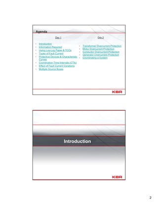
This document provides an agenda and overview for a two-day seminar on overcurrent protection and coordination for industrial applications. Day 1 will cover topics such as the information required for coordination, time-current curves, fault currents, protective devices and coordination time intervals. Day 2 will focus on overcurrent protection for specific equipment such as transformers, motors, conductors and generators. The presenter's biography is provided, noting his engineering experience in power system planning and protection, including serving as an assistant technical editor for an IEEE standard on overcurrent protection.
1
Overcurrent Protection &Coordination for
Industrial Applications
Doug Durand, P.E.
(PowerPoint assistance by Alok Gupta)
IEEE Continuing Education Seminar - Houston, TX
February 16-17, 2010
Presenter Bio
1986 – Received BSEE degree from University of Texas at Austin and joined
the Planning department of West Texas Utility
1987 – Joined Brown & Root (now KBR).
Currently Senior Principal Engineer in charge of KBR’s Technical Services
group. The group’s primary tasks involve power system studies including short-
circuit, load flow, motor starting, overcurrent coordination, underground cable
ampacity, ground mat, arc-flash, harmonic load flow, transient stability, and relay
configuration/setting.
Professional Engineer (Texas)
IEEE Member
Assistant Technical Editor of the IEEE Std 399 – Brown Book (revision 1990)
2.
2
Day 1
▫ Introduction
▫Information Required
▫ Using Log-Log Paper & TCCs
▫ Types of Fault Current
▫ Protective Devices & Characteristic
Curves
▫ Coordination Time Intervals (CTIs)
▫ Effect of Fault Current Variations
▫ Multiple Source Buses
Day 2
▫ Transformer Overcurrent Protection
▫ Motor Overcurrent Protection
▫ Conductor Overcurrent Protection
▫ Generator Overcurrent Protection
▫ Coordinating a System
Agenda
Introduction
4
Protection Objectives
• ServiceContinuity & Selective Fault Isolation
13.8 kV
480 V
13.8 kV/480 V
2.5 MVA
5.75%
• Faults should be quickly
detected and cleared with a
minimum disruption of service.
• Protective devices perform this
function and must be adequately
specified and coordinated.
• Errors in either specification or
setting can cause nuisance
outages.
Types of Protection
• Distance
• High Impedance Differential
• Current Differential
• Under/Over Frequency
• Under/Over Voltage
• Over Temperature
• Overcurrent
• Overload
5.
5
Coordinating Overcurrent Devices
•Tools of the trade “in the good ole days…”
Coordinating Overcurrent Devices
• Tools of the trade “in the good ole days…”
6.
6
Coordinating Overcurrent Devices
•Tools of the trade “in the good ole days…”
Coordinating Overcurrent Devices
• Tools of the trade “in the good ole days…”
8
Using Log-Log Paper& TCCs
0.01
0.1
1
10
100
1000
TimeInSeconds
0.5 1 10 100` 1000 10000
Current in Amperes
Time-Current Characteristic Curve (TCC)
Log-Log Plots
Why log-log paper?
• Log-Log scale compresses
values to a more manageable
range.
• I2t withstand curves plot as
straight lines.
effectively
steady state
1 minute
typical motor
acceleration
typical fault
clearing
5 cycles
(interrupting)
1 cycle
(momentary)
FLC = 1 pu Fs = 13.9 pu Fp = 577 pu
I2t withstand
curves plot as
straight lines
9.
9
0.01
0.1
1
10
100
1000
TimeInSeconds
0.5 1 10100` 1000 10000
Current in Amperes
5000 hp Motor TCC
Plotting A Curve
FLC = 598.9 A
LRA = 3593.5 A
Accel. Time = 2 s
4.16 kV 5000 hp
90% PF, 96% η, 598.9 A
3593.5 LRA, 2 s start
M
13.8 kV
4.16 kV
13.8/4.16 kV
10 MVA
6.5%
0.01
0.1
1
10
100
1000
TimeInSeconds
0.5 1 10 100` 1000 10000
Current in Amperes
5000 hp Motor TCC with Fault on Motor Terminal
Plotting Fault Current & Scale Adjustment
FLC = 598.9 A
LRA = 3593.5 A
Accel. Time = 2 s
4.16 kV 5000 hp
90% PF, 96% η, 598.9 A
3593.5 LRA, 2 s start
15 kA
15 kA
x 10 A
M
13.8 kV
4.16 kV
13.8/4.16 kV
10 MVA
6.5%
10.
10
0.01
0.1
1
10
100
1000
TimeInSeconds
0.5 1 10100` 1000 10000
Current in Amperes
5000 hp Motor TCC with Fault on Transformer Primary
Voltage Scales
4.16 kV 5000 hp
90% PF, 96% η, 598.9 A
3593.5 LRA, 2 s start
15 kA
149.3 kA
x 10 A
45 kA= (45 x 13.8/4.16)
= 149.3 kA @ 4.16 kV
45 kA @ 13.8 kV
= ? @ 4.16 kV
x 100 A @ 4.16 kV
15 kA
M
13.8 kV
4.16 kV
13.8/4.16 kV
10 MVA
6.5%
Types of Fault Currents
11.
11
Fault Current Options
ANSI
•Momentary Symmetrical
• Momentary Asymmetrical
• Momentary Crest
• Interrupting Symmetrical
• Adjusted Interrupting Symmetrical
IEC
• Initial Symmetrical (Ik
’’)
• Peak (Ip)
• Breaking (Ib)
• Asymmetrical Breaking (Ib,asym)
Momentary
Current
Crest/Peak
Interrupting/Breaking
Initial Symmetrical
Fault Current Options
• Symmetrical currents are most appropriate.
• Momentary asymmetrical should be considered when setting
instantaneous functions.
• Use of duties not strictly appropriate, but okay.
• Use of momentary/initial symmetrical currents lead to conservative CTIs.
• Use of interrupting currents will lead to lower, but still conservative CTIs.
Momentary
Current
Crest/Peak
Interrupting/Breaking
Initial Symmetrical
12.
12
Protective Devices &Characteristic
Curves
Electromechanical Relays (EM)
1 10 100
0.01
0.1
100
1
10
MULTIPLES OF PICK-UP SETTING
TIMEINSECONDS
TimeDial
Settings
½
1
2
3
10
IFC 53
RELAY
Very Inverse Time
Time-Current
Curves
13.
13
M
4.16 kV
4.16 kV
5000hp
FLC = 598.9 A
SF = 1.0
IFC
53
800/5 Set AT = 4
Electromechanical Relays – Pickup Calculation
The relay should pick-up for current
values above the motor FLC ( ~ 600 A).
For the IFC53 pictured, the available
ampere-tap (AT) settings are 0.5, 0.6,
0.7, 0.8, 1, 1.2, 1.5, 2, 2.5, 3, & 4.
For this type of relay, the primary pickup
current was calculated as:
PU = CT Ratio x AT
PU = (800/5) x 3 = 480 A (too low)
= (800/5) x 4 = 640 A (107%, okay)
1 10 100
0.01
0.1
100
1
10
MULTIPLES OF PICK-UP SETTING
TIMEINSECONDS
M
4.16 kV
4.16 kV
5000 hp
598.9 A, SF = 1
IFC
53
15 kA
800/5 Setting = 4 AT, ?? TD
1.21 s1.05 sTime Dial 10
0.34 s0.30 sTime Dial 3
0.08 s0.07 sTime Dial ½
10000/640
= 15.6
15000/640
= 23.4
Multiple of Pick-up
10 kA15 kAFault Current
IFC 53 Relay Operating Times0.30
1.05
1.21
0.34
10 kA
23.4
TimeDialSettings
½
1
2
3
10
IFC 53
RELAY
Very Inverse Time
Time-Current Curves
15.6
0.080.07
Electromechanical Relays – Operating Time Calculation
15
Power CBs
Power MCB
Cutler-HammerRMS 520 Series
Sensor = 3200
LT Pickup = 1 (3200 Amps)
LT Band = 4
ST Pickup = 2.5 (8000 Amps)
ST Band = 0.3 (I^x)t = OUTPower FCB
Cutler-Hammer RMS 520 Series
Sensor = 1200
LT Pickup = 1 (1200 Amps)
LT Band = 2
ST Pickup = 4 (4500 Amps)
ST Band = 0.1 (I^x)t = OUT
Amps X 100 (Plot Ref. kV=0.48)
Seconds
Power MCB – 3P
47.4 kA @ 0.48 kV
Power FCB – 3P
90.2 kA @ 0.48 kV
16-SWGR-02A
0.48 kV
PWR MCB
3200 A
PWR FCB
1600 A
LT Pickup
LT Band
ST Pickup
ST Band
Insulated & Molded Case CB
16-SWGR-02A
0.48 kV
Insulated Case MCB
1200 A
Molded Case CB
250 A
Insulated Case MCB
Frame = 1250 Plug = 1200 A
LT Pickup = Fixed (1200 A)
LT Band = Fixed
ST Pickup = 4 x (4000 A)
ST Band = Fixed (I^2)t = IN
Override = 14000 A
Molded Case CB
HKD
Size = 250 A
Terminal Trip = Fixed
Magnetic Trip = 10
Insulated Case MCB
11 kA @ 0.48 kV
Amps X 100 (Plot Ref. kV=0.48)
Seconds
Fault current
< Inst. Override
16.
16
Insulated & MoldedCase CB
16-SWGR-02A
0.48 kV
Insulated Case MCB
1200 A
Molded Case CB
250 A
Insulated Case MCB
Frame = 1250 Plug = 1200 A
LT Pickup = Fixed (1200 A)
LT Band = Fixed
ST Pickup = 4 x (4000 A)
ST Band = Fixed (I^2)t = IN
Override = 14000 A
Molded Case CB
HKD
Size = 250 A
Terminal Trip = Fixed
Magnetic Trip = 10
Insulated Case MCB
42 kA @ 0.48 kV
Amps X 100 (Plot Ref. kV=0.48)
Seconds
Fault current
> Inst. Override
Power Fuses
MCC 1
4.16 kV
Mtr Fuse
Mtr Fuse
JCL (2/03)
Standard 5.08 kV
5R
Seconds
Amps X 10 (Plot Ref. kV=4.16 kV)
Minimum
Melting
Total
Clearing
Mtr Fuse
15 kA @
4.16 kV
17.
17
Coordination Time Intervals(CTIs)
Primary devices sense, operate
& clear the fault first.
Backup devices wait for sufficient
time to allow operation of primary
devices.
Coordination Time Intervals (CTIs)
The CTI is the amount of time allowed between a
primary device and its upstream backup.
Feeder
Main
When two such
devices are
coordinated such
that the primary
device “should”
operate first at all
fault levels, they are
“selectively”
coordinated.
18.
18
It depends.
Coordination TimeIntervals – EM
Main
Feeder
30 kA
Feeder
Main
30 kA
Amps X 100 (Plot Ref. kV=13.8)
Seconds
In the good old days,
What typical CTI would we
want between the feeder and
the main breaker relays?
? s
Coordination Time Intervals – EM
On what did it depend?
Remember the TD setting?
It is continuously adjustable
and not exact.
So how do you really
know where TD = 5?
FIELD TESTING !
(not just hand set)
19.
19
Coordination Time Intervals– EM
Feeder
30 kA
3x (9.6 kA), 3.3 s
5x (16 kA), 1.24 s
8x (25.6 kA), 0.63 s
Plotting the field test points.
Amps X 100 (Plot Ref. kV=13.8)
Seconds
“3x” means 3 times pickup
3 * 8 = 24 A (9.6 kA primary)
5 * 8 = 40 A (16 kA primary)
8 * 8 = 64 A (25.6 kA primary)
Coordination Time Intervals – EM
Feeder
30 kA
Amps X 100 (Plot Ref. kV=13.8)
Seconds
So now, if test points are not
provided what should the CTI
be?
0.4 s
0.3 s
But, if test points are provided
what should the CTI be?
Feeder
Main
30 kA
Main w/o testing
Main w/ testing
0.4 s0.3 s
20.
20
Coordination Time Intervals– EM
Where does the 0.3 s or 0.4 s come from?
Feeder
Main
30 kA
1. breaker operating time
2. CT, relay errors
3. disk overtravel
(Feeder breaker)
(both)
(Main relay only)
0.40 s0.30 sTOTAL
0.22 s0.12 sCT, relay errors
0.10 s0.10 sDisk over travel
0.08 s0.08 sbreaker 5 cycle
Hand SetTested
Coordination Time Intervals – EM
Buff Book (taken from Tables 15-1 & 15-2)
Red Book (per Section 5.7.2.1)
Components
Obviously, CTIs can be a
subjective issue.
Components Field Tested
0.08 s
0.10 s
0.17 s
0.35 s
0.08 s
0.10 s
0.12 s
0.30 s
21.
21
Coordination Time Intervals– EM & SS
So, lets move forward a few years….
For a modern (static) relay what part of the
margin can be dropped?
Disk overtravel
So if one of the two relays is static, we can
use 0.2 s, right?
It depends
Feeder (SS)
Main (EM)
CTI = 0.3 s
(because disk OT is
still in play)
Feeder (EM)
Main (SS)
CTI = 0.2 s
Coordination Time Intervals – EM & SS
Main (EM)
Feeder (SS)
0.3 s
disk OT still applicable
Feeder (SS)
Main (EM)
Feeder (SS)
30 kA @ 13.8 kV
Main (EM)
Main (SS)
Feeder EM
0.2 s
Feeder (EM)
30 kA @ 13.8 kV
Main (SS)
Feeder (EM)
Main (SS)
Amps X 100 (Plot Ref. kV=13.8)
Seconds
Amps X 100 (Plot Ref. kV=13.8)
22.
22
Coordination Time Intervals– EM/SS with Banded Devices
OC Relay combinations with banded devices
disk over travel
CT, relay errors
operating time
CTI
√ 0.1 s
√ 0.12 s
x -
0.22 s
disk over travel
CT, relay errors
operating time
CTI
x -
√ 0.12 s
x -
0.12 s
Static Trip or
Molded Case
Breaker
Static Relay
Power
Fuse
Static Trip or
Molded Case
Breaker
EM Relay
Power
Fuse
EM-Banded
0.22 s 0.12 s
SS-Banded
Coordination Time Intervals – EM/SS with Banded Devices
EM RelayPWR MCB SS RelayPWR MCB
PWR MCB
EM Relay
25 kA 25 kA
Amps X 100 (Plot Ref. kV=0.48)
Seconds
Amps X 100 (Plot Ref. kV=0.48)
PWR MCB
SS Relay
23.
23
Coordination Time Intervals– Banded Devices
• Banded characteristics include
tolerances & operating times.
• There is no
intentional/additional time delay
needed between two banded
devices.
• All that is required is clear
space (CS).
Amps X 100 (Plot Ref. kV=0.48)
Seconds
Coordination Time Intervals – Summary
Buff Book (Table 15-3 – Minimum CTIsa)
24.
24
Effect of FaultCurrent Variations
CTI & Fault Current Magnitude
Main
Feeder
F2 = 20 kA
Feeder
Main
F2 = 20 kA
Amps X 100 (Plot Ref. kV=13.8)
Seconds
0.06 s
F1 = 10 kA
F1 = 10 kA
0.2 s
Inverse relay characteristics
imply
Relay
Current
Operating
Time
If CTI is set based on 10 kA, it
reduces to less than the
desired value at 20 kA.
For a fault current of 10 kA the
CTI is 0.2 s.
For a fault current of 20 kA the
CTI is 0.06 s.
25.
25
Total Bus Faultversus Branch Currents
M MM
15 kA
1 kA2 kA0.8 kA1.2 kA
10 kA
• For a typical distribution bus all feeder relays will see a slightly different
maximum fault current.
• Years back, the simple approach was to use the total bus fault current as
the basis of the CTI, including main incomer.
• Using the same current for the main led to a margin of conservatism.
Total Bus Fault versus Branch Currents
10 kA
M
15 kA
Main
Feeder
15 kA
Amps X 100 (Plot Ref. kV=13.8)
Seconds
10 kA
Amps X 100 (Plot Ref. kV=13.8)
15 kA
Main
Feeder
0.2 s
0.8 s
Using Total Bus
Fault Current of
15 kA
Using Actual
Maximum Relay
Current of 10 kA
26.
26
Curve Shaping
Amps X100 (Plot Ref. kV=13.8)
Seconds
Most modern relays
include multiple OC
Elements.
Using a definite time
characteristic (or delayed
instantaneous) can
eliminate the affect of
varying fault current levels.
15 kA
20 kA
10 kA
0.2 s
Multiple Source Buses
27.
27
Multiple Source Buses
•When a bus includes multiple sources, care must be
taken to not coordinate all source relays at the total
fault current.
• Source relays should be plotted only to their respective
fault currents or their “normalized” plots.
• Plotting the source curves to the total bus fault current
will lead to much larger than actual CTIs.
Multiple Source Buses
Amps X 100 (Plot Ref. kV=13.8)
Seconds
Amps X 100 (Plot Ref. kV=13.8)
Plot to Full Fault
Level
Plot to Actual
Relay Current
2
1
30 kA12 kA
0.2 s
30 kA12 kA
1.1 s
2
1
12 kA 18 kA
30 kA 1
2 3
28.
28
Adjusted Pickup Method
•Many software packages include the facility to
adjust/shift the characteristics of the source relays to
line up at the bus maximum fault currents.
• The shift factor (SF) is calculated using:
SF = Bus Fault / Relay Current
Adjusted Pickup Method
Amps X 100 (Plot Ref. kV=13.8)
Seconds
Amps X 100 (Plot Ref. kV=13.8)
Without shift factor
both pickups = 3000 A.
With shift factor relay 2
pickup shifts to 7500 A.
SF = (30/12) * 3000 A
21
30 kA12 kA
0.2 s
30 kA
1
2
0.2 s
12 kA 18 kA
30 kA 1
2 3
29.
29
Multiple Source Buses
10kA 5 kA10 kA
Fa = 25 kA Fb = 25 kA
15 kA (Fa)
10 kA (Fb)
Bus A Bus B
• Different fault locations cause different flows in tie.
SF(Fa) = 25 / (10 + 5) = 1.67
SF(Fb) = 25 / 10 = 2
• Preparing a TCC for each unique location can confirm defining case.
• Cases can be done for varying sources out of service & breaker logic
used to enable different setting groups.
Partial Differential Relaying
• Typically used on double-ended
systems with normally closed
ties.
• Automatically discriminates
between Bus A and Bus B faults.
• Eliminates need for relay on tie
breaker.
• Saves coordination step.
51A
Ip1+Ip2
Source 1 Source 251B
Feeder A Feeder B
Ip2
Is2
Is2
Is1
Is2
Bus A Bus B
0
Ip2
Is1+Is2
Ip1
30.
30
Partial Differential Relaying
51ASource1 Source 251B
Feeder A Feeder B
0
0
Is1
Is1
Is1
Bus A Bus B
Is1
Ip1
0
Ip1
Open
Ip1
Embellish notes
Scheme works even with one
source out of service.
However, the relay in the open
source must remain in operation
since the relay in the remaining
source sees no operating current.
Partial Differential Relaying
Show same 3 source 1 tie example
31.
31
Directional Current Relaying
67
BusA Bus B
67
• Directional overcurrent (67) relays should be used on double-ended
line-ups with normally closed ties and buses with multiple sources.
• Protection is intended to provide more sensitive and faster detection
of faults in the upstream supply system.
Transformer Overcurrent Protection
32.
32
Transformer Overcurrent Protection
NECTable 450.3(A) defines overcurrent setting requirements for primary &
secondary protection pickup settings.
Transformer Overcurrent Protection
C37.91 defines the ANSI
withstand protection limits.
Withstand curve defines
thermal & mechanical limits of
a transformer experiencing a
through-fault. thermal
withstand
25 x FLC
@ 2s
based on
transformer Z
mechanical
withstand
33.
33
Transformer Overcurrent Protection
Requirementto protect for
mechanical damage is based
on frequency of through faults
& transformer size.
Right-hand side (thermal) used
for setting primary protection.
Left-hand side (mechanical)
used for setting secondary
protection.
thermal
withstand
25 x FLC
@ 2 s
based on
transformer Z
mechanical
withstand
Transformer Overcurrent Protection
FLC = 2.4 MVA/(√3 x 13.8) = 100.4 A
Relay PU must be ≤ 600% FLC = 602.4 A
Using a relay setting of 2.0 x CT, the relay
PU = 2 x 200 = 400 A
400 / 100.4 = 398% so okay
Time Dial depends on level of protection
desired.
Seconds
Amps X 10 (Plot Ref. kV=13.8)
2.4 MVA, 5.75% Z
∆-Y Resistor Ground
PWR-MCB
13.8 kV
480 V
13.8/0.48 kV
2.4 MVA
5.75%
PWR-MCB
34.
34
Transformer Overcurrent Protection
∆-YConnections – Phase-To-Phase Faults
• Assume
1:1 turns ratio
X1 = X2 = X0
3-Phase fault current = base current.
• Phase-phase fault current is typically
0.866 per unit.
• This current transforms to 0.5
(0.866/√3) per unit on the delta phase
winding and adds up to 1.0 per unit on
the line-side.
• The CTIs need to be set assuming
1.15 (1/0.866) per unit fault current.
0
0.5
0.866
0.866
0.5
0.5
0.5
1.0
A
C
B
a
c
b
Add TCC here to show
primary relay clipped
at 100% secondary
fault current
coordinated with a
secondary relay
clipped at 86% of the
secondary fault
current.
Trim down notes on
left and summarize
that we normally don’t
mess with this issue…
Transformer Overcurrent Protection
∆-Y Connections – Phase-To-Ground Faults
1.0
0.577
0
0.577
0.577
0
0
A
C
B
a
c
b
0 0
• Assume
1:1 turns ratio
X1 = X2 = X0
3-Phase fault current = base current.
• The 1 per unit phase-ground fault
current transforms to 0.577 (1/√3) per
unit on the delta phase.
• The transformer damage curve is
shifted to the left to ensure protection.
Add TCC with a
shifted and non-shifted
transformer damage
curve….
35.
35
Will be deletedonce the previous page is fixed.
Amps X 10 (Plot Ref. kV=13.8)
2.4 MVA, 5.75% Z
∆-Y Resistor Ground
PWR-MCB
13.8 kV
480 V
13.8/0.48 kV
2.4 MVA
5.75%
PWR-MCB Seconds
2.4 MVA, 5.75% Z
∆-Y Solid Ground
PWR-MCB
Amps X 10 (Plot Ref. kV=13.8)
For resistance-
grounded secondary
For a solidly-grounded
secondary
• Withstand
curve shifted
left due to
∆-Y xfmr.
•More difficult
to provide
protection.
Transformer Overcurrent Protection
Inrush Current
• Use of 8-12 times FLC @ 0.1 s is an
empirical approach based on EM
relays.
• The instantaneous peak value of the
inrush current can actually be much
higher than 12 times FLC.
• The inrush is not over at 0.1 s, the dot
just represents a typical rms
equivalent of the inrush from
energization to this point in time.
Seconds
Amps X 10 (Plot Ref. kV=13.8)
2.4 MVA, 5.75% Z
∆-Y Resistor Ground
PWR-MCB
13.8 kV
480 V
13.8/0.48 kV
2.4 MVA
5.75%
PWR-MCB
8-12 x FLC
(typical)
36.
36
Transformer Overcurrent Protection
Settingthe primary inst. protection
• The primary relay instantaneous
(50) setting should clear both the
inrush & the secondary fault current.
• It was common to use the
asymmetrical rms value of
secondary fault current (1.6 x sym)
to establish the instantaneous
pickup, but most modern relays filter
out the DC component.
Seconds
Amps X 10 (Plot Ref. kV=13.8)
2.4 MVA, 5.75% Z
∆-Y Resistor Ground
PWR-MCB
13.8 kV
480 V
13.8/0.48 kV
2.4 MVA
5.75%
PWR-MCB
8-12 x FLC
(typical)
Transformer Overcurrent Protection
∆-Y Connection & Ground Faults
• A secondary L-G fault is not sensed by the ground devices on the
primary (∆) side.
• Low-resistance and solidly grounded systems are coordinated as
separately derived systems.
0
0
0
37.
37
Transformer Overcurrent Protection
∆-YConnection & Ground Faults
• The ground resistor size is selected to
limit the fault current while still providing
sufficient current for coordination.
• The resistor ratings include a maximum
continuous current that must be
considered.
Motor Overcurrent Protection
38.
38
Motor Overcurrent Protection
•Fuse provides short-circuit
protection.
• 49 or 51 device provide motor
overload protection.
• Overload pickup depends on
motor FLC and service factor.
• The time delay for the 49/51
protection is based on motor
stall time.
Seconds
Amps X 10 (Plot Ref. kV=4.16)
1000 hp
4.16 kV
650% LRC
Bussmann
JCL Size 9R
GE Multilin 469
Standard O/L Curve
Pickup = 1.01 X FLC
Curve Multiplier = 3
Hot
M
Motor Overcurrent Protection
• In the past, instantaneous OC
protection was avoided on contactor-
fed motors since the contactors could
not clear high short-circuits.
• With modern relays, a delayed
instantaneous can be used if its
setting is coordinated with the
contactor interrupting rating.
Amps X 10 (Plot Ref. kV=4.16)
Seconds
1000 hp
4.16 kV
650% LRC
Bussmann
JCL Size 9R
GE Multilin 469
Standard O/L Curve
Pickup = 1.01 X FLC
Curve Multiplier = 3
Hot
Contactor
6 kA Int.
M
39.
39
Motor Overcurrent Protection
•The instantaneous setting for a
breaker-fed motor must be set to pass
the motor asymmetrical inrush.
• Can be done with a pickup over the
asymmetrical current.
• Can be done using a lower pickup with
time delay to allow DC component to
decay out.
Seconds
Amps X 10 (Plot Ref. kV=4.16)
1000 hp
4.16 kV
650% LRC
GE Multilin 469
Standard O/L Curve
Pickup = 1.01 X FLC
Curve Multiplier = 3
Hot
M
3 kA @ 4.16 kV
Conductor Overcurrent Protection
40.
40
Conductor Overcurrent Protection
LVCables
NEC 240.4 Protection of Conductors – conductors shall be protected against
overcurrent in accordance with their ampacities
(B) Devices Rated 800 A or Less – the next higher standard device rating
shall be permitted
(C) Devices Rated over 800 A – the ampacity of the conductors shall be ≥ the
device rating
NEC 240.6 Standard Ampere Ratings
(A) Fuses & Fixed-Trip Circuit Breakers – cites all standard ratings
(B) Adjustable Trip Circuit Breakers – Rating shall be equal to maximum
setting
(C) Restricted Access Adjustable-Trip Circuit Breakers – Rating can be
equal to setting if access is restricted
Conductor Overcurrent Protection
MV Cables
NEC 240.101 (A) Rating or Setting of Overcurrent Protective Devices
Fuse rating ≤ 3 times conductor ampacity
Relay setting ≤ 6 times conductor ampacity
41.
41
Conductor Overcurrent Protection
1– 3/C 350 kcmil
Copper Rubber
Tc = 90 deg. C
Seconds
Amps X 100 (Plot Ref. V=600)
• The insulation temperature rating
is typically used as the operating
temperature (To).
• The final temperature (Tf) depends
on the insulation type (typically
150 deg. C or 250 deg. C).
• When calculated by hand, you
only need one point and then draw
in at a -2 slope.
Generator Overcurrent Protection
42.
42
Generator Overcurrent Protection
•A generators fault current
contribution decays over time.
• Overcurrent protection must
allow both for moderate
overloads & be sensitive enough
to detect the steady state
contribution to a system fault.
Generator Overcurrent Protection
• Voltage controlled/ restrained
relays (51V) are commonly
used.
• The pickup at full restraint is
typically ≥ 150% of Full Load
Current (FLC).
• The pickup at no restraint must
be < FLC/Xd
.
FLC/Xd
43.
43
Generator 51V PickupSetting Example
Fg = FLC/Xd = 903 / 2.8 = 322.5 A
51V pickup (full restraint) > 150% FLC = 1354 A
51V pickup (no restraint) < 322.5 A
1200/5
Fg
51V
12.47 kV
19500 kVA
903 A
Xd = 280%
Generator 51V Pickup Setting Example
51V Setting > 1354/1200 = 1.13
Using 1.15, 51V pickup = 1.15 x 1200 A = 1380 A
With old EM relays,
51V pickup (no restraint) = 25% of 1380 A
= 345 A (> 322.5 A, not good)
With new relays a lower MF can be set, such that 51V
pickup (no restraint) = 15% of 1380 A
= 207 A (< 322.5, so okay)
44.
44
Generator 51V Settingson TCC
GTG-101A
No Load
Constant Excitation
Total Fault Current
15% x Pickup
Pickup = 1.15 x
CT-Sec
30 kA
Seconds
Amps X 10 (Plot Ref. kV=12.47)
• Limited guidance on
overcurrent protection
(C37.102 Section 4.1.1)
with respect to time delay.
• Want to avoid nuisance
tripping, especially on
islanded systems, so
higher TDs are better.
Coordinating a System
45.
45
Coordinating a System
•TCCs show both
protection & coordination.
• Most OC settings should
be shown/confirmed on
TCCs.
• Showing too much on a
single TCC can make it
impossible to read.
Coordinating a System
Showing a
vertical slice of
the system can
reduce
crowding, but
still be hard to
read.
Upstream
equipment is
shown on
multiple and
redundant
TCCs.
47
Coordinating a System:TCC-2
• The switchgear feeder breaker settings
established on TCC-1 set the basis for this
curve.
• The main breaker is set to be selective with
the feeder at all fault levels.
• A CTI marker is not required since the
characteristic curves include all margins and
breaker operating times.
• The main breaker curve is clipped at its
through-fault current instead of the total bus
fault current to allow tighter coordination of
the upstream relay.
Zone Map
Coordinating a System: TCC-3
• The LV switchgear main breaker settings
established on TCC-2 set the basis for this curve.
• The transformer damage curve is based on
frequent faults and is not shifted since the
transformer is resistance grounded.
• The primary side OC relay is selective with the
secondary main and provides adequate
transformer and feeder cable protection.
• The OC relay instantaneous high enough to pass
the secondary fault current and transformer
inrush current.
Zone Map
48.
48
Coordinating a System:TCC-307J
• This curve sets the basis for the upstream
devices since its motor is the largest on the
MCC.
• Motor starting and overload protection is
acceptable.
• Motor feeder cable protection is acceptable
• The motor relay includes a second definite
time unit to provide enhanced protection.
• The definite time function is delay to allow
the asymmetrical inrush current to pass.
Zone Map
Coordinating a System: TCC-4
• The 307J motor relay settings established
on TCC-307J set the basis for this curve.
• The tie breaker relay curve is plotted to the
total bus fault current to be conservative.
• The main breaker relay curve is plotted to its
let-through current.
• A coordination step is provided between the
tie and main relay although this decision is
discretionary.
• All devices are selectively coordinated at all
fault current levels.
• The definite time functions insulation the
CTIs from minor fault current variations..
Zone Map
49.
49
Coordinating a System:TCC-5
• The MV MCC main breaker settings
established on TCC-4 set the basis for this
curve.
• The transformer damage curve is based on
frequent faults and is not shifted since the
transformer is resistance grounded.
• The primary side OC relay is selective with the
secondary main and provides adequate
transformer and feeder cable protection.
• The OC relay instantaneous high enough to
pass the secondary fault current and
transformer inrush current.
Zone Map
Coordinating a System: TCC-Comp
• Due to the compressor size, this curve may
set the basis for the MV switchgear main
breaker.
• Motor starting and overload protection is
acceptable.
• Short-circuit protection is provided by the
relay/breaker instead of a fuse as with the
1000 hp motor.
• The short-circuit protection is delay 50 ms to
avoid nuisance tripping.
Zone Map
50.
50
Coordinating a System:TCC-6
• The feeder breaker settings established on
TCC-3, TCC-4, and TCC-Comp are shown
as the basis for this curve.
• The settings for feeder 52A1 (to the 2.4
MVA) could be omitted since it does not
define any requirements.
• A coordination step is provided between the
tie and main relay although this decision is
discretionary.
• All devices are selectively coordinated at all
fault current levels.
• The definite time functions insulation the
CTIs from minor fault current variations.
Zone Map
TCC Zone Map
TCC-G1
TCC-G2
51.
51
Coordination Pop Quiz#1
Does this TCC look good??
• There is no need to maintain a
coordination interval between
feeder breakers.
• The CTI between the main and
feeder 2 is appropriate unless all
relays are electromechanical and
hand set.
TR-FDR2
Main
2000/5
600/5
OCR
OCR
TR-FDR1
400/5 OCR
SWGR-1
0.301 s
0.3 s
Coordination Pop Quiz #2
Does this TCC look good??
• The CTIs shown between main
and both feeders are sufficient.
• Assuming testing EM relays, the
0.615s CTI cannot be reduced
since the 0.304s CTI is at the
limit.
• The main relay time delay is
actually too fast since the CTI at
30 kA is less than 0.2s.
FDR-2
Main-1
2000/5
600/5
OCR
OCR
FDR-1
400/5 OCR
SWGR-3
0.615 s
0.304 s
52.
52
Coordination Pop Quiz#3
Does this TCC look good??
• The marked CTIs are okay,
but….
• A main should never include an
instantaneous setting.
0.472 s
0.325 s
Coordination Pop Quiz #4
Does this TCC look good??
• Primary relay pickup is 525% of
transformer FLC, thus okay.
• Transformer frequent fault
protection is not provided by the
primary relay, but this is okay –
adequate protection is provided
by the secondary main.
• Cable withstand protection is
inadequate. Adding a 50 to the
primary relay would be
appropriate and fix this.
53.
53
Coordination Pop Quiz#5
Does this TCC look good??
• Crossing of feeder
characteristics is no problem.
• There is no need to maintain an
intentional time margin between
two LV static trip units – clear
space is sufficient.
0.021 s
Coordination Pop Quiz #6
Does this TCC look good??
• The source relays should not be
plotted to the full bus fault level
unless their plots are shifted
based on:
SF = Total fault current / relay
current.
• Assuming each relay actually
sees only half of the total fault
current, the CTI is actually much
higher than 0.3s.
0.03 s
54.
54
Coordination Pop Quiz#7
Does this TCC look good??
• There are two curves to be
concerned with for a 51V – full
restraint and zero restraint.
• Assuming the full restraint curve
is shown, it is coordinated too
tightly with the feeder.
• The 51V curve will shift left and
lose selectivity with the feeder if
a close-in fault occurs and the
voltage drops.
0.302 s
Coordination Software
• Computer-aided coordination software programs
originated in the late 1980s.
• The accuracy of the device characteristic curves was
often highly questionable.
• There are numerous, much more powerful programs
available today, many of which are very mature.
• Even still, the accuracy of the protective devices
functions and characteristics is still extremely critical.
55.
55
Coordination Software
• Formany years clients maintained separate impedance
models for power studies and protective device models
for coordination studies.
• Integrated models are now the norm and are required to
support arc-flash studies.
Information Required
58
Equipment Ratings
• buscontinuous rating affects
relay pickup (different for LV
and MV)
• short-circuit rating must be
adequate but does not affect
overcurrent coordination
• differing fault current affect
coordination
Equipment Ratings
• adds to short-circuit
• LRC, acceleration time, & hot/
cold stall times affect time
curve selection
59.
59
Protective Devices
• Make& model
• CT Ratio
• Tap & time dial
settings (old days)
• setting files (today)
• Trip device type
• LT, ST, Inst settings
References
60.
60
Selected References
• AppliedProtective Relaying – Westinghouse
• Protective Relaying – Blackburn
• IEEE Std 242 – Buff Book
• IEEE Std 141 – Red Book
• IEEE Std 399 – Brown Book
• IEEE C37.90 – Relays
• IEEE C37.91 – Transformer Protection
• IEEE C37.102 – Guide for AC Generator Protection
• NFPA 70 – National Electrical Code
120