Downloaded 227 times
![Transformation Ratio
0
0
0
0 0
0
0 0
2 2 2
2 2 2
0 0
2 2 2 2
0 0 0
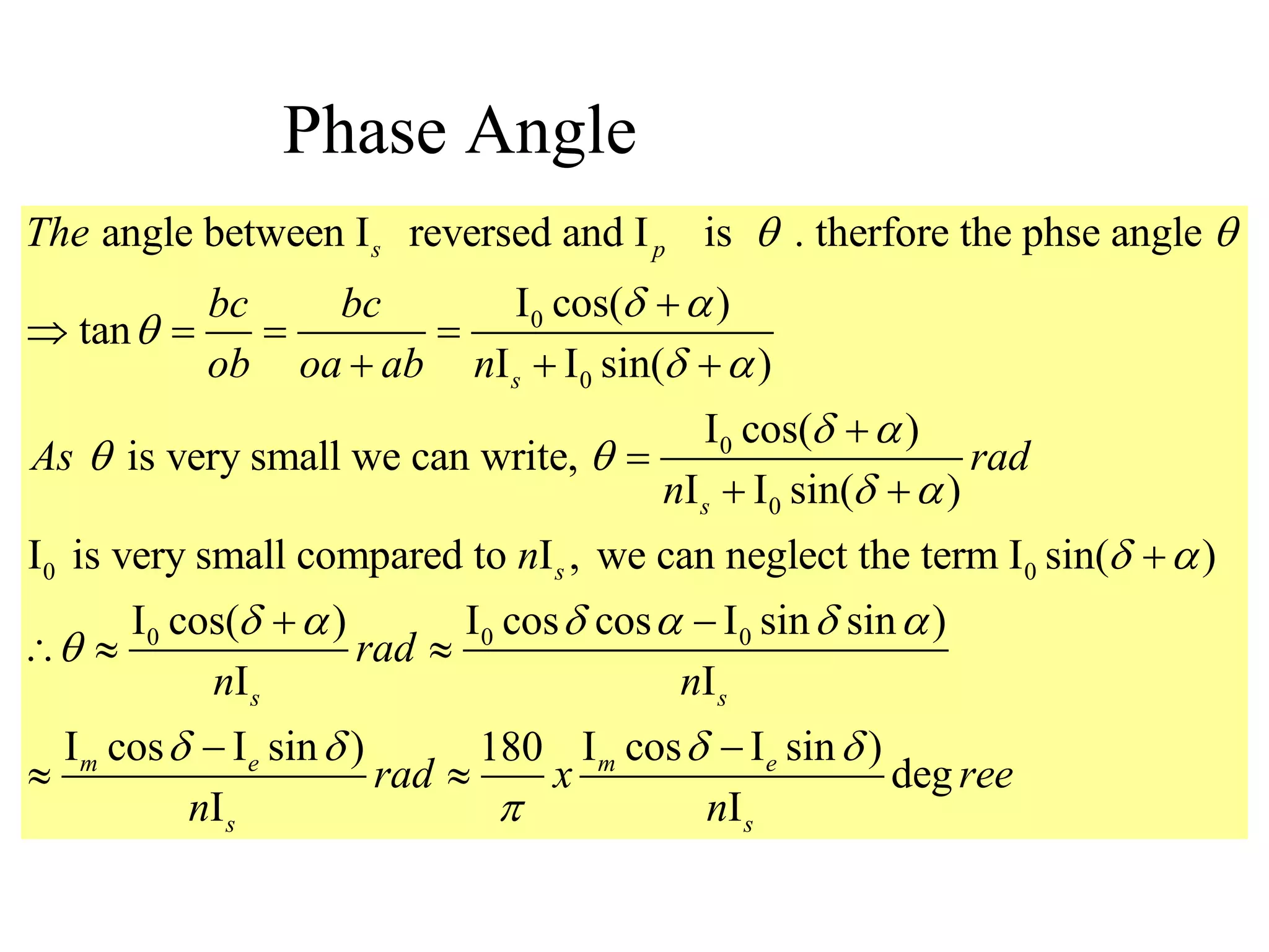
90 ; ; ; and oc=
bc= sin(90 ) cos( );
cos(90 ) sin( )
, (oc) (oa+ab) (bc)
( ) [ sin( )] [ cos( )]
( ) sin ( ) 2 sin( ) c
s p
p s
s s
bac ac I oa nI I
I I
ab I I
Now
I nI I I
nI I nI I I
2
2 2
0 0
2 2 1/2
0 0
os ( )
( ) 2 sin( )
[( ) 2 sin( ) ]
s s
p s s
nI nI I I
I nI nI I I
](https://image.slidesharecdn.com/ctpt-200329144602/75/Current-Transformer-and-Potential-Transformer-14-2048.jpg)
![2 2 1/2
0 0
0 0
2 2 2 1/2
0 0
0
[( ) 2 sin( ) ]
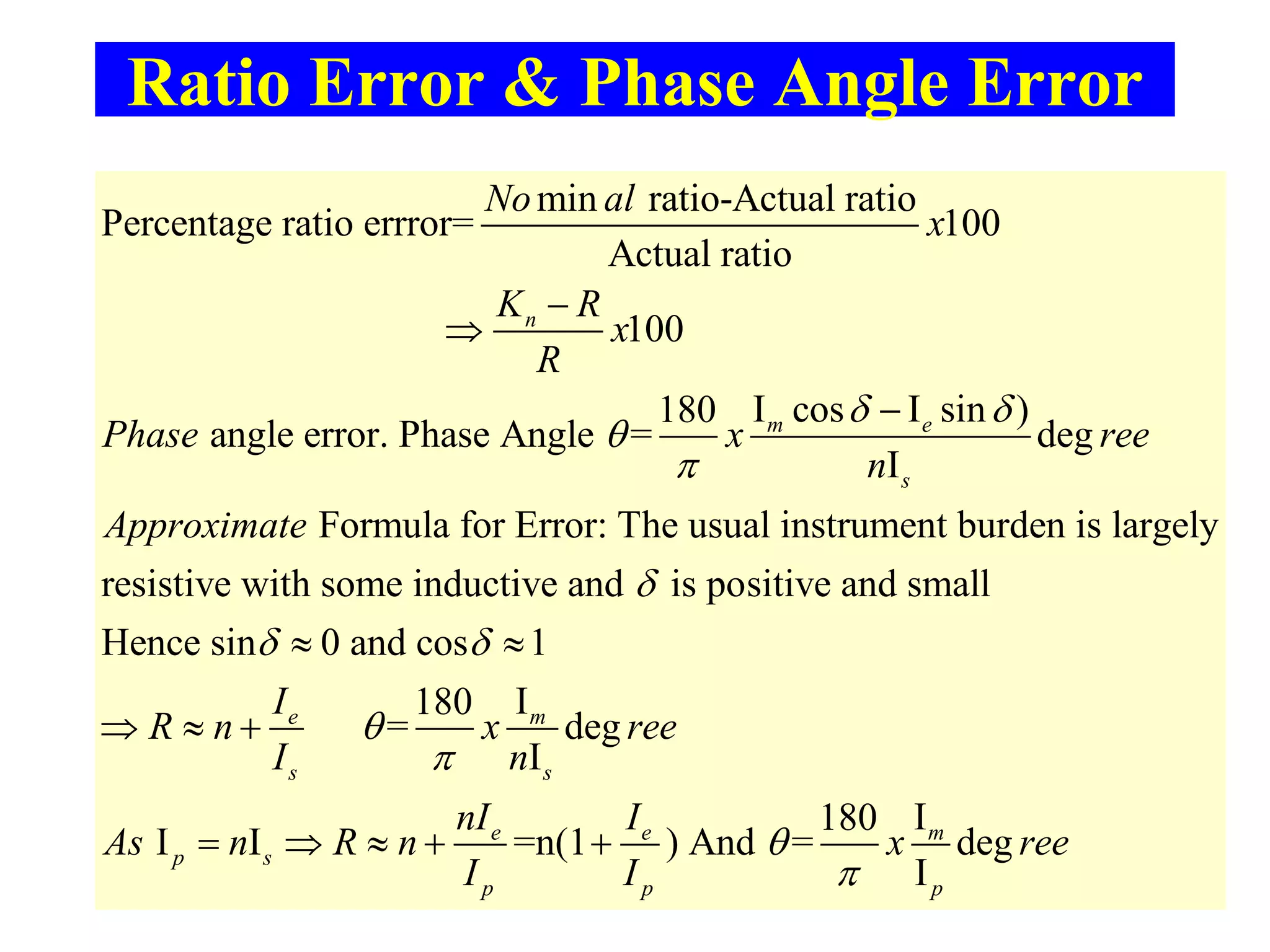
Ratio=R=
a well designed CT ; Usually is less than 1 % of
[( ) 2 sin( ) sin ( )]
R
sin( )
p s s
s s
s p
p s
p s s
s s
s
s
I nI nI I I
Transformation
I I
In I nI I I
I nI
I nI nI I I
I I
nI I
n
I
=
0
0
0 0
sin( )
sin cos
(sin cos cos sin )
, cos and sin
s
m e
s s
m e
I
I
I I I
R n n
I I
Where I I I I
Transformation Ratio](https://image.slidesharecdn.com/ctpt-200329144602/75/Current-Transformer-and-Potential-Transformer-15-2048.jpg)
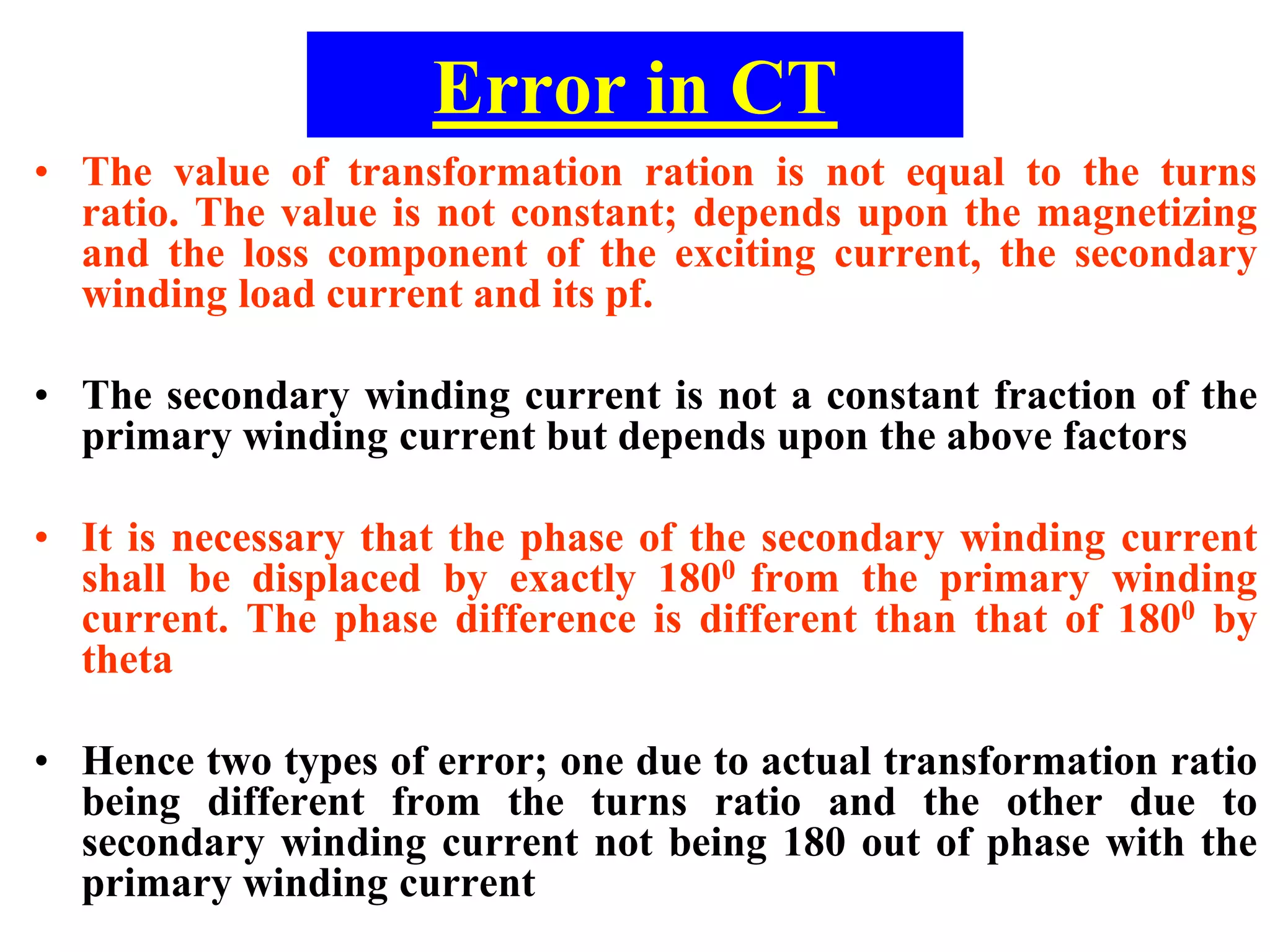
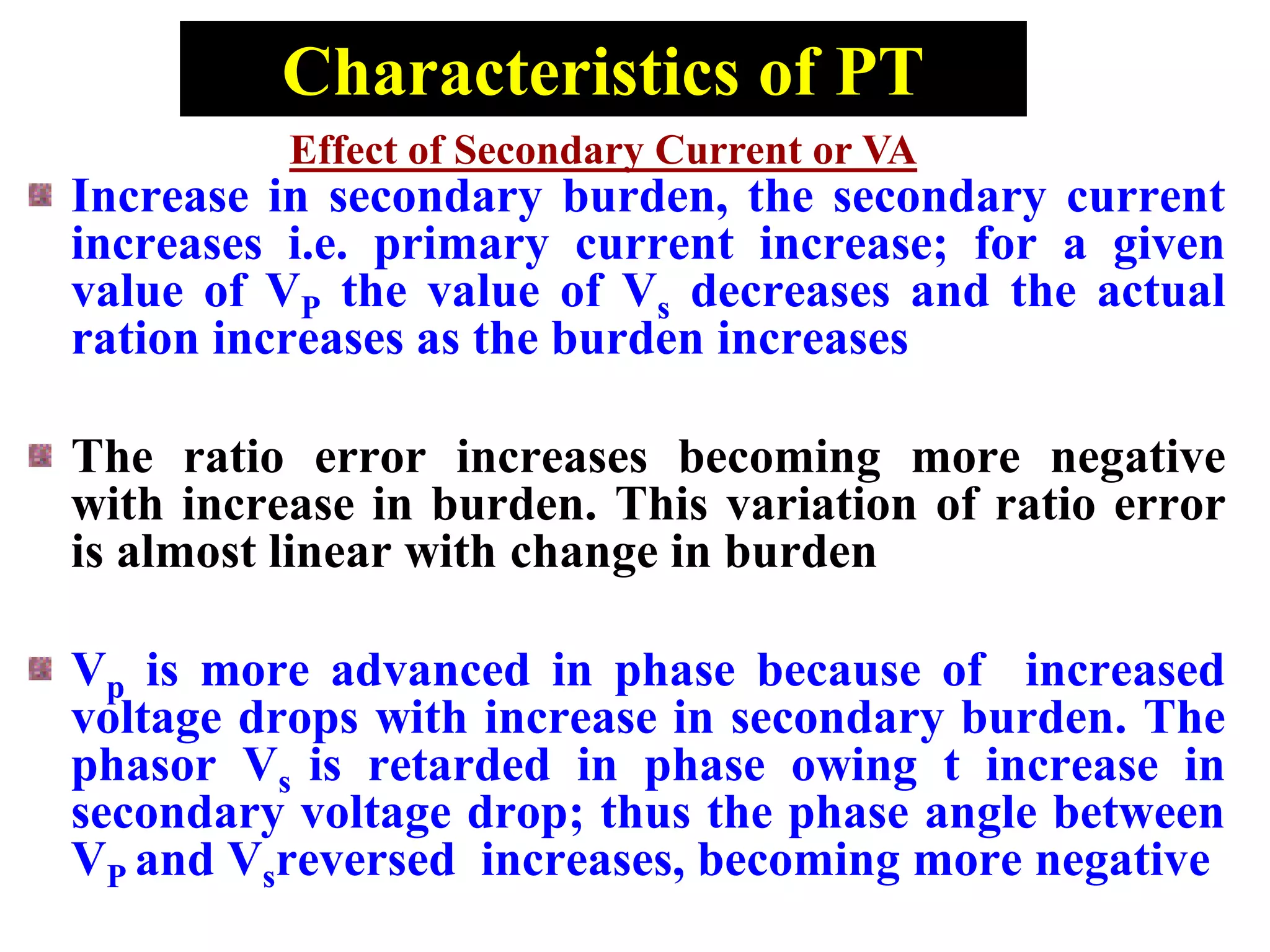
![ERRORS IN PT
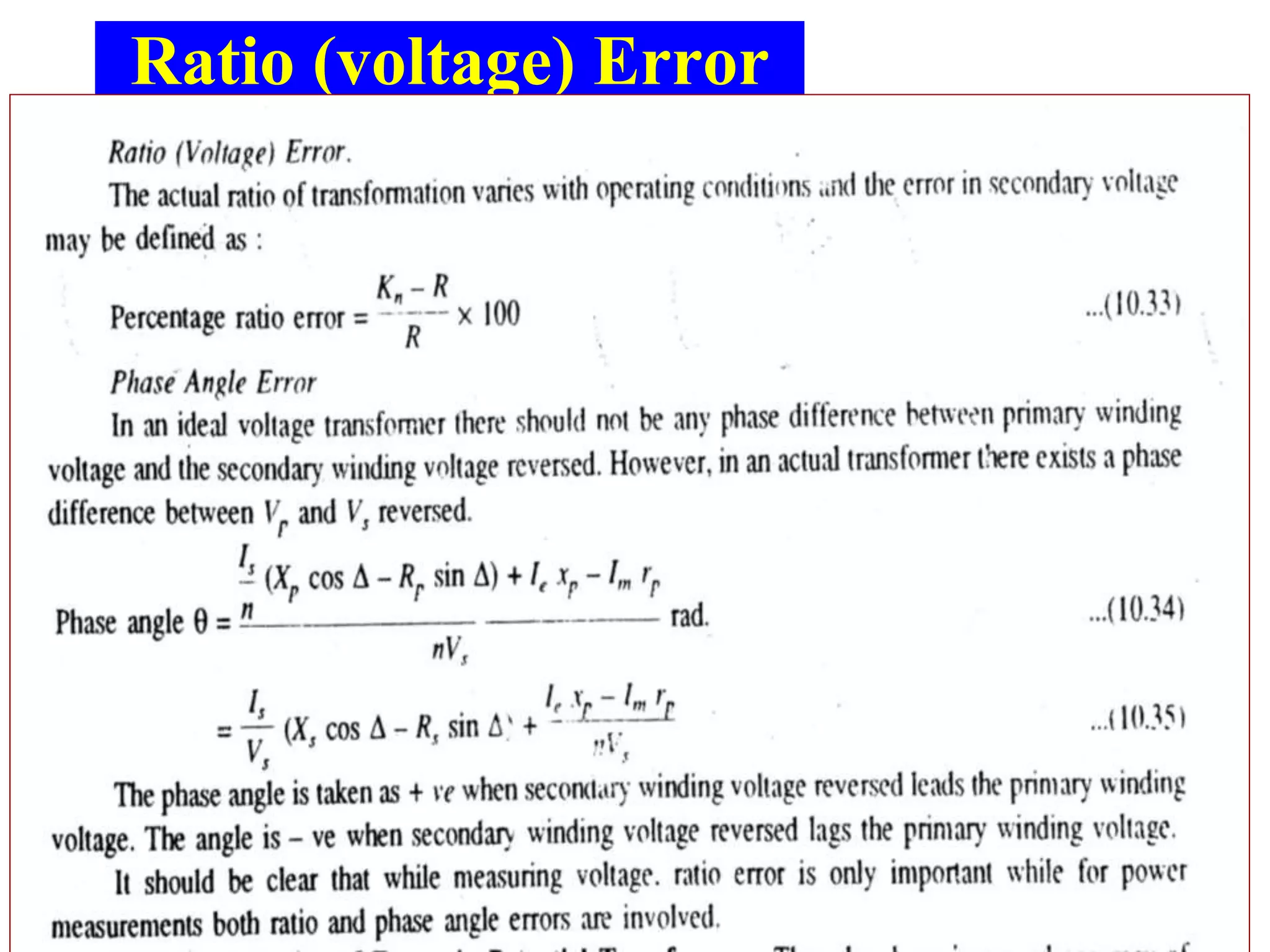
Ratio (voltage) Error
• The actual ratio of transformation varies
with operating conditions and the error in
secondary voltage may be defined;
• percentage ration error=[(Kn-R)/R]x100](https://image.slidesharecdn.com/ctpt-200329144602/75/Current-Transformer-and-Potential-Transformer-42-2048.jpg)

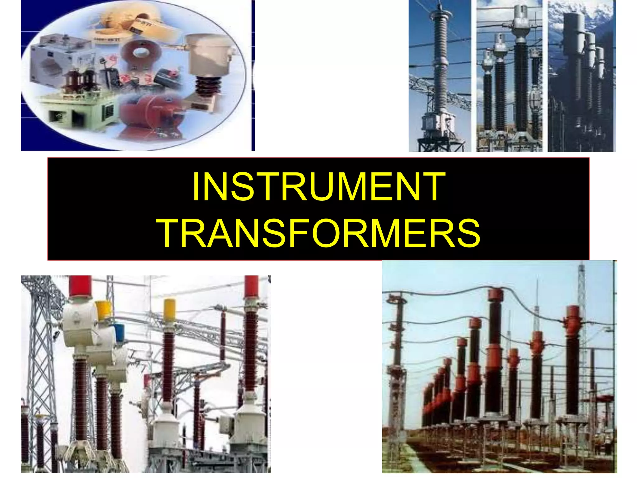
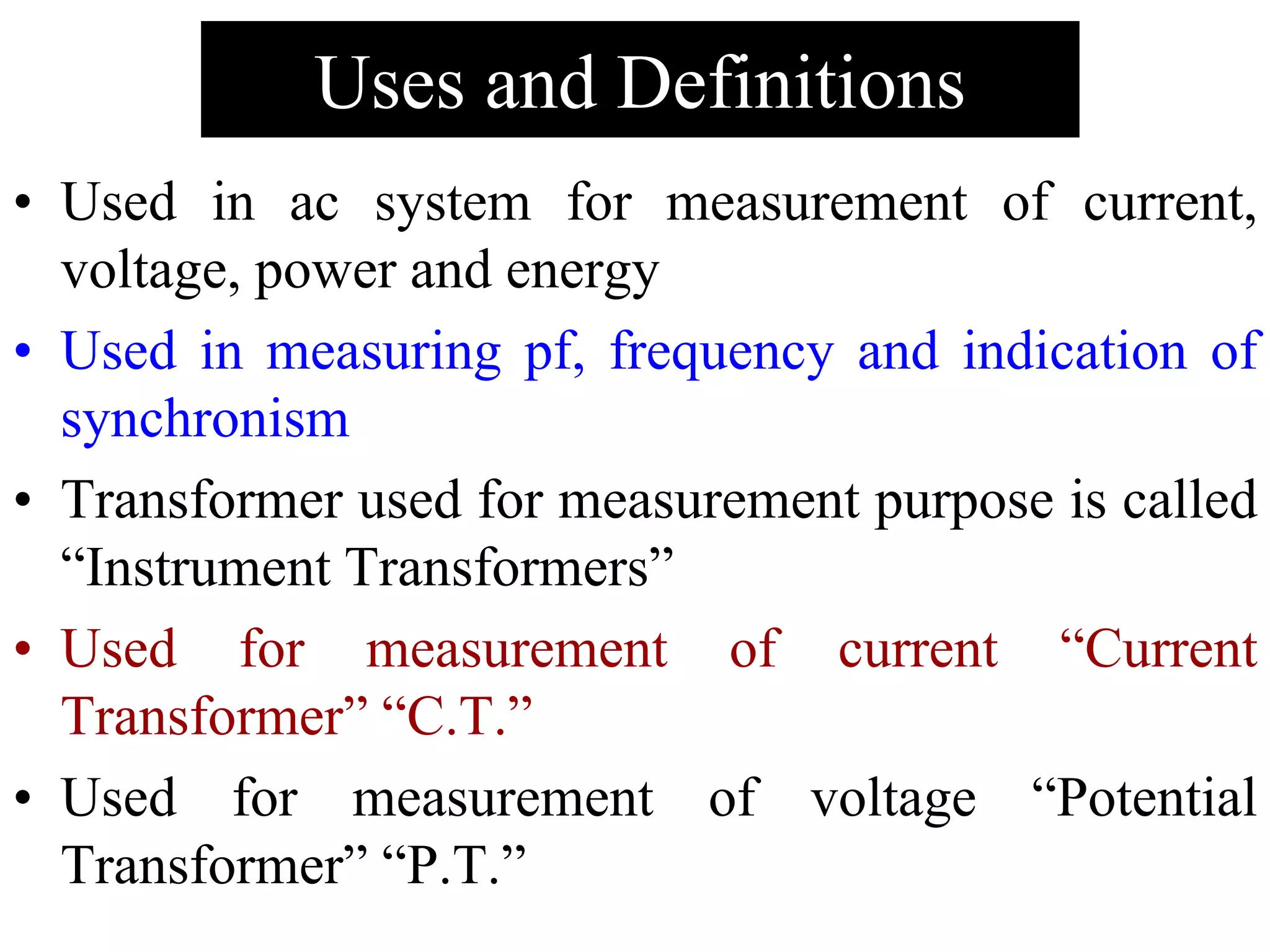
The document discusses instrument transformers, primarily focusing on current transformers (CT) and potential transformers (PT) used in AC systems for measuring current, voltage, power, and energy. It highlights their advantages, such as improved accuracy, isolation from high voltage circuits, and cost-effectiveness, while also addressing disadvantages including errors due to phase angles and transformer design complexities. Key relationships, error types, and operational characteristics of both CT and PT are also outlined.


![Electrical measurement & measuring instruments [emmi (nee-302) -unit-2]](https://cdn.slidesharecdn.com/ss_thumbnails/electricalmeasurementmeasuringinstrumentsemmi-nee-302-unit-2-170607090943-thumbnail.jpg?width=640&height=640&fit=bounds)