Downloaded 3,315 times


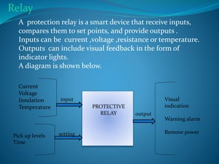


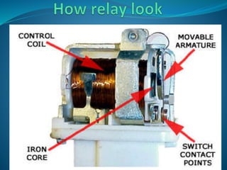
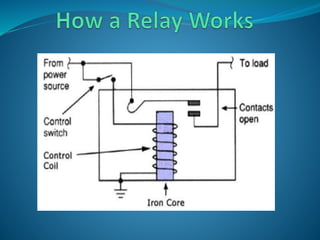

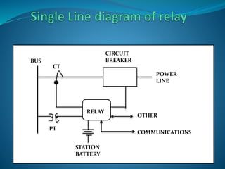

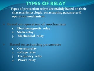


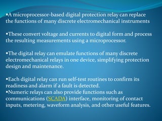
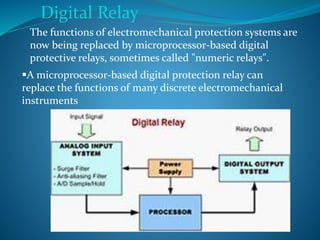
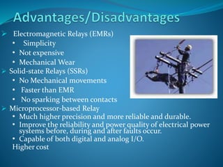


Flexible AC Transmission Systems (FACTS) enhance power transmission efficiency and quality through advanced power electronic technologies. Protective relays are critical devices designed to detect faults in electrical circuits, isolate affected sections, and minimize damage by tripping circuit breakers quickly. Various types of relays exist, each serving specific operational needs and functionalities, with an increasing trend towards microprocessor-based digital relays for improved reliability and monitoring capabilities.