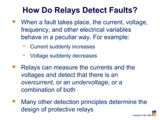
Power System Protection
    Fundamentals


What should we teach students
about power system protection?


                            Copyright © SEL 2008
Agenda

   Why protection is needed
   Principles and elements of the protection
    system
   Basic protection schemes
   Digital relay advantages and enhancements


                                           Copyright © SEL 2008
Disturbances: Light or Severe
   The power system must maintain acceptable
    operation 24 hours a day
       Voltage and frequency must stay within certain
        limits

   Small disturbances
       The control system can handle these
       Example: variation in transformer or generator load

   Severe disturbances require a protection
    system
       They can jeopardize the entire power system
       They cannot be overcome by a control system Copyright © SEL 2008
Power System Protection

Operation during severe disturbances:
      System element protection
      System protection
      Automatic reclosing
      Automatic transfer to alternate power
       supplies
      Automatic synchronization


                                               Copyright © SEL 2008
Electric Power System Exposure to
          External Agents


                               Copyright © SEL 2008
Damage to Main Equipment


                           Copyright © SEL 2008
Protection System


 A series of devices whose main purpose
 is to protect persons and primary electric
power equipment from the effects of faults


            The “Sentinels”


                                         Copyright © SEL 2008
Blackouts

    Characteristics            Main Causes
   Loss of service in a      Overreaction of the
    large area or              protection system
    population region
                              Bad design of the
   Hazard to human life       protection system
   May result in
    enormous economic
    losses


                                            Copyright © SEL 2008
Short Circuits Produce High
             Currents

                        Three-Phase Line
                                                     a
                                                     b
                                                     c
                             I

       Substation                     Fault


Thousands of Amps   I
                                    Wire

                                              Copyright © SEL 2008
Electrical Equipment Thermal Damage
                  t


        Damage                   Damage Curve
          Time


                                                 I
                      In   Imd   Short-Circuit
    Rated Value
                                   Current
                                                 Copyright © SEL 2008
Mechanical Damage During
                   Short Circuits
    Very destructive in busbars, isolators, supports,
     transformers, and machines
    Damage is instantaneous
 Mechanical
  Forces
         f1                   f2
    i1
                   i2

Rigid Conductors        f1(t) = k i1(t) i2(t)
                                                Copyright © SEL 2008
The Fuse


           Fuse


           Transformer


                  Copyright © SEL 2008
Protection System Elements

   Protective relays
   Circuit breakers
   Current and voltage transducers
   Communications channels
   DC supply system
   Control cables

                                  Copyright © SEL 2008
Three-Phase Diagram of the Protection
               Team


                                 Copyright © SEL 2008
DC Tripping Circuit


                      Copyright © SEL 2008
Circuit Breakers


                   Copyright © SEL 2008
Current Transformers


Very High Voltage CT
                       Medium-Voltage CT


                                  Copyright © SEL 2008
Voltage Transformers


                     Medium Voltage


               Note: Voltage transformers
               are also known as potential
High Voltage   transformers
                                    Copyright © SEL 2008
Protective Relays


                    Copyright © SEL 2008
Examples of Relay Panels


                        Microprocessor-
                         Based Relay

Old Electromechanical


                                  Copyright © SEL 2008
How Do Relays Detect Faults?
   When a fault takes place, the current, voltage,
    frequency, and other electrical variables
    behave in a peculiar way. For example:
       Current suddenly increases
       Voltage suddenly decreases

   Relays can measure the currents and the
    voltages and detect that there is an
    overcurrent, or an undervoltage, or a
    combination of both
   Many other detection principles determine the
    design of protective relays
                                             Copyright © SEL 2008
Main Protection Requirements
         Reliability
             Dependability
             Security
         Selectivity
         Speed
             System stability
             Equipment damage
             Power quality
         Sensitivity
             High-impedance faults
             Dispersed generation    Copyright © SEL 2008
Primary Protection


                     Copyright © SEL 2008
Primary Protection Zone Overlapping
 Protection
 Zone A
                    52      Protection
                            Zone B
   To Zone A
   Relays
                            To Zone B
                            Relays


 Protection
 Zone A
               52          Protection
                           Zone B
   To Zone A
   Relays                   To Zone B
                            Relays
                                 Copyright © SEL 2008
Backup Protection

                     Breaker 5
                       Fails
             C                   D
A                                              E

    1    2       5         6         11   12


             T
B                                              F

    3    4       7         8         9    10


                                               Copyright © SEL 2008
Typical Short-Circuit Type
          Distribution

Single-Phase-Ground:   70–80%
Phase-Phase-Ground:    17–10%
Phase-Phase:           10–8%
Three-Phase:           3–2%


                                Copyright © SEL 2008
Balanced vs.
      Unbalanced Conditions
                               Ia
Ic
                     Ic

              Ia


 Ib
                               Ib
Balanced System    Unbalanced System
                                Copyright © SEL 2008
Decomposition of an Unbalanced
           System


                           Copyright © SEL 2008
Power Line Protection Principles

    Overcurrent (50, 51, 50N, 51N)
    Directional Overcurrent (67, 67N)
    Distance (21, 21N)
    Differential (87)


                                      Copyright © SEL 2008
Application of Inverse-Type
          Relays
       Relay                     t
       Operation
       Time


I
            Radial Line


               Fault      Load

                                 Copyright © SEL 2008
Inverse-Time Relay Coordination


I


                            Distance
t


         }   ∆T   } ∆T    } ∆T
                            Distance
                             Copyright © SEL 2008
Addition of Instantaneous OC
           Element

         Relay                    t
       Operation
           Time


 I
            Radial Line


                   Fault   Load

                                      Copyright © SEL 2008
50/51 Relay Coordination


I


                           Distance
t


           } ∆T    } ∆T    } ∆T
                           Distance
                               Copyright © SEL 2008
Directional Overcurrent Protection
        Basic Applications


             K


              L

                              Copyright © SEL 2008
Directional Overcurrent Protection
                Basic Principle
                     V             I


           F2                            F1

                           Relay

      Reverse Fault (F2)               Forward Fault (F1)
  I
                                                     V

                      V                  I
                                                    Copyright © SEL 2008
Overcurrent Relay Problem

                                       E
                 I SETTING    ≈
                                Z S1 + (0.8) Z L1

 Relay     operates when the following condition
  holds:
                   I FAULT = I a > I SETTING

 As Z s1
        changes, the relay’s “reach” will change,
  since setting is fixed
                                               E
                 I FAULT ( LIMIT )   =
                                         ′
                                       Z S1 + (0.8) Z L1
                                                           Copyright © SEL 2008
Distance Relay Principle
                                          L
                        d
                    I a , Ib , Ic

                                                   Radial
                    21              Three-Phase
Va ,Vb ,Vc                                          Line
                                     Solid Fault


Suppose Relay Is Designed to Operate
When:
             | Va |≤ (0.8) | Z L1 || I a |
                                                   Copyright © SEL 2008
The Impedance Relay Characteristic

                R 2 + X 2 ≤ Z r21

                      X        Plain Impedance Relay
    Operation Zone

     Z ≤ Z r1                       Radius Zr1
                             Zr1

                                           R


                                                 Copyright © SEL 2008
Need for Directionality

        F2                F1
    1         2      3            4    5       6


    RELAY 3                   X
    Operation Zone
                                  F1

                         F2                R
Nonselective
Relay Operation

                                               Copyright © SEL 2008
Directionality Improvement
           F2                  F1
      1           2    3             4    5         6


  RELAY 3                  X
  Operation Zone                     Directional Impedance
                                F1   Relay Characteristic


                      F2                      R
The Relay Will
Not Operate for
This Fault
                                                     Copyright © SEL 2008
Mho Element Characteristic
(Directional Impedance Relay)

 Operates when:   V ≤ I Z M cos( ϕ − ϕ MT )
                  Z ≤ Z M cos( ϕ − ϕ MT )


                                            Copyright © SEL 2008
Three-Zone Distance Protection
Time

                               Zone 3
                     Zone 2
       Zone 1

       1         2     3        4    5    6


                                          Time
                Zone 1 Is Instantaneous
                                           Copyright © SEL 2008
Line Protection With Mho Elements
            X

                           C

                       B


               A
                               R
                   D


           E
                                   Copyright © SEL 2008
Circular Distance Relay Characteristics
      X               X
          PLAIN               OFFSET
          IMPEDANCE           MHO (2)

             R

                              R
                          X
      X
                              LENS
            MHO               (RESTRICTED MHO 1)


                 R                R

      X               X

          OFFSET              TOMATO
          MHO (1)             (RESTRICTED MHO 2)


                 R            R

                                        Copyright © SEL 2008
Semi-Plane Type Characteristics
    X                    X
           DIRECTIONAL
                                   RESTRICTED
                                   DIRECTIONAL

             R

                                   R
    X                        X

        REACTANCE                RESTRICTED
                                 REACTANCE


                  R                    R

    X                    X

                 OHM
                                 QUADRILATERAL

                  R
                                   R

                                           Copyright © SEL 2008
Distance Protection
                  Summary

   Current and voltage information
   Phase elements: more sensitive than 67
    elements
   Ground elements: less sensitive than
    67N elements
   Application: looped and parallel lines

                                        Copyright © SEL 2008
Directional Comparison
Pilot Protection Systems


                           Copyright © SEL 2008
Permissive Overreaching
     Transfer Trip


                          Copyright © SEL 2008
Basic POTT Logic


                             Key XMTR


Zone 2 Elements
                       AND                      Trip
          RCVR


                                        Copyright © SEL 2008
Directional Comparison
   Blocking Scheme


                         Copyright © SEL 2008
Basic DCB Logic


Zone 3                          Key XMTR

         Carrier Coordination

            Time Delay
               CC
Zone 2              0
                                    Trip
RCVR

                                     Copyright © SEL 2008
Differential Protection Principle

             Balanced CT Ratio

      CT                             CT
                Protected
                Equipment                 External
                                          Fault


                 50       IDIF = 0

No Relay Operation if CTs Are Considered Ideal
                                          Copyright © SEL 2008
Differential Protection Principle


    CTR                            CTR
            Protected
            Equipment
                  Internal
                    Fault


             50       IDIF > ISETTING


          Relay Operates
                                         Copyright © SEL 2008
Problem of Unequal CT Performance
             CT                          CT
                      Protected
                      Equipment               External
                                              Fault


                      50      IDIF ¹ 0

    False differential current can occur if a CT
     saturates during a through-fault
    Use some measure of through-current to
     desensitize the relay when high currents are
     present                                   Copyright © SEL 2008
Possible Scheme – Percentage
Differential Protection Principle
           ĪSP                         ĪRP
    CTR           Protected                  CTR
                  Equipment


             ĪS                   ĪR

                    Relay
                     (87)

     Compares:        I OP = I S + I R
                                   | IS | + | IR |
                      k ×I RT   =k×
                                          2          Copyright © SEL 2008
Differential Protection Applications
       Bus protection
       Transformer protection
       Generator protection
       Line protection
       Large motor protection
       Reactor protection
       Capacitor bank protection
       Compound equipment protection
                                        Copyright © SEL 2008
Differential Protection
                     Summary
   The overcurrent differential scheme is simple
    and economical, but it does not respond well to
    unequal current transformer performance
   The percentage differential scheme responds
    better to CT saturation
   Percentage differential protection can be
    analyzed in the relay and the alpha plane
   Differential protection is the best alternative
    selectivity/speed with present technology
                                                Copyright © SEL 2008
Multiple Input Differential Schemes
                             Examples

          Differential Protection Zone
                                              ĪSP                ĪRP


                                                    ĪT

     I1         I2     I3     I4
                                                         OP


Bus Differential: Several Inputs
                                         Three-Winding Transformer
                                          Differential: Three Inputs

                                                              Copyright © SEL 2008
Advantages of Digital Relays

                    Compatibility with
                                         Low maintenance
 Multifunctional    digital integrated
                                         (self-supervision)
                         systems


Highly sensitive,
                                           Highly reliable
  secure, and           Adaptive
                                         (self-supervision)
   selective


Reduced burden
                     Programmable
      on                                     Low Cost
                        Versatile
 CTs and VTs


                                                        Copyright © SEL 2008
Synchrophasors Provide a
“Snapshot” of the Power System


                           Copyright © SEL 2008
The Future
   Improvements in computer-based
    protection
   Highly reliable and viable communication
    systems (satellite, optical fiber, etc.)
   Integration of control, command,
    protection, and communication
   Improvements to human-machine
    interface
   Much more                          Copyright © SEL 2008

Protection primer

  • 1.
    Power System Protection Fundamentals What should we teach students about power system protection? Copyright © SEL 2008
  • 2.
    Agenda  Why protection is needed  Principles and elements of the protection system  Basic protection schemes  Digital relay advantages and enhancements Copyright © SEL 2008
  • 3.
    Disturbances: Light orSevere  The power system must maintain acceptable operation 24 hours a day  Voltage and frequency must stay within certain limits  Small disturbances  The control system can handle these  Example: variation in transformer or generator load  Severe disturbances require a protection system  They can jeopardize the entire power system  They cannot be overcome by a control system Copyright © SEL 2008
  • 4.
    Power System Protection Operationduring severe disturbances:  System element protection  System protection  Automatic reclosing  Automatic transfer to alternate power supplies  Automatic synchronization Copyright © SEL 2008
  • 5.
    Electric Power SystemExposure to External Agents Copyright © SEL 2008
  • 6.
    Damage to MainEquipment Copyright © SEL 2008
  • 7.
    Protection System Aseries of devices whose main purpose is to protect persons and primary electric power equipment from the effects of faults The “Sentinels” Copyright © SEL 2008
  • 8.
    Blackouts Characteristics Main Causes  Loss of service in a  Overreaction of the large area or protection system population region  Bad design of the  Hazard to human life protection system  May result in enormous economic losses Copyright © SEL 2008
  • 9.
    Short Circuits ProduceHigh Currents Three-Phase Line a b c I Substation Fault Thousands of Amps I Wire Copyright © SEL 2008
  • 10.
    Electrical Equipment ThermalDamage t Damage Damage Curve Time I In Imd Short-Circuit Rated Value Current Copyright © SEL 2008
  • 11.
    Mechanical Damage During Short Circuits  Very destructive in busbars, isolators, supports, transformers, and machines  Damage is instantaneous Mechanical Forces f1 f2 i1 i2 Rigid Conductors f1(t) = k i1(t) i2(t) Copyright © SEL 2008
  • 12.
    The Fuse Fuse Transformer Copyright © SEL 2008
  • 13.
    Protection System Elements  Protective relays  Circuit breakers  Current and voltage transducers  Communications channels  DC supply system  Control cables Copyright © SEL 2008
  • 14.
    Three-Phase Diagram ofthe Protection Team Copyright © SEL 2008
  • 15.
    DC Tripping Circuit Copyright © SEL 2008
  • 16.
    Circuit Breakers Copyright © SEL 2008
  • 17.
    Current Transformers Very HighVoltage CT Medium-Voltage CT Copyright © SEL 2008
  • 18.
    Voltage Transformers Medium Voltage Note: Voltage transformers are also known as potential High Voltage transformers Copyright © SEL 2008
  • 19.
    Protective Relays Copyright © SEL 2008
  • 20.
    Examples of RelayPanels Microprocessor- Based Relay Old Electromechanical Copyright © SEL 2008
  • 21.
    How Do RelaysDetect Faults?  When a fault takes place, the current, voltage, frequency, and other electrical variables behave in a peculiar way. For example:  Current suddenly increases  Voltage suddenly decreases  Relays can measure the currents and the voltages and detect that there is an overcurrent, or an undervoltage, or a combination of both  Many other detection principles determine the design of protective relays Copyright © SEL 2008
  • 22.
    Main Protection Requirements  Reliability  Dependability  Security  Selectivity  Speed  System stability  Equipment damage  Power quality  Sensitivity  High-impedance faults  Dispersed generation Copyright © SEL 2008
  • 23.
    Primary Protection Copyright © SEL 2008
  • 24.
    Primary Protection ZoneOverlapping Protection Zone A 52 Protection Zone B To Zone A Relays To Zone B Relays Protection Zone A 52 Protection Zone B To Zone A Relays To Zone B Relays Copyright © SEL 2008
  • 25.
    Backup Protection Breaker 5 Fails C D A E 1 2 5 6 11 12 T B F 3 4 7 8 9 10 Copyright © SEL 2008
  • 26.
    Typical Short-Circuit Type Distribution Single-Phase-Ground: 70–80% Phase-Phase-Ground: 17–10% Phase-Phase: 10–8% Three-Phase: 3–2% Copyright © SEL 2008
  • 27.
    Balanced vs. Unbalanced Conditions Ia Ic Ic Ia Ib Ib Balanced System Unbalanced System Copyright © SEL 2008
  • 28.
    Decomposition of anUnbalanced System Copyright © SEL 2008
  • 29.
    Power Line ProtectionPrinciples  Overcurrent (50, 51, 50N, 51N)  Directional Overcurrent (67, 67N)  Distance (21, 21N)  Differential (87) Copyright © SEL 2008
  • 30.
    Application of Inverse-Type Relays Relay t Operation Time I Radial Line Fault Load Copyright © SEL 2008
  • 31.
    Inverse-Time Relay Coordination I Distance t } ∆T } ∆T } ∆T Distance Copyright © SEL 2008
  • 32.
    Addition of InstantaneousOC Element Relay t Operation Time I Radial Line Fault Load Copyright © SEL 2008
  • 33.
    50/51 Relay Coordination I Distance t } ∆T } ∆T } ∆T Distance Copyright © SEL 2008
  • 34.
    Directional Overcurrent Protection Basic Applications K L Copyright © SEL 2008
  • 35.
    Directional Overcurrent Protection Basic Principle V I F2 F1 Relay Reverse Fault (F2) Forward Fault (F1) I V V I Copyright © SEL 2008
  • 36.
    Overcurrent Relay Problem E I SETTING ≈ Z S1 + (0.8) Z L1  Relay operates when the following condition holds: I FAULT = I a > I SETTING  As Z s1 changes, the relay’s “reach” will change, since setting is fixed E I FAULT ( LIMIT ) = ′ Z S1 + (0.8) Z L1 Copyright © SEL 2008
  • 37.
    Distance Relay Principle L d I a , Ib , Ic Radial 21 Three-Phase Va ,Vb ,Vc Line Solid Fault Suppose Relay Is Designed to Operate When: | Va |≤ (0.8) | Z L1 || I a | Copyright © SEL 2008
  • 38.
    The Impedance RelayCharacteristic R 2 + X 2 ≤ Z r21 X Plain Impedance Relay Operation Zone Z ≤ Z r1 Radius Zr1 Zr1 R Copyright © SEL 2008
  • 39.
    Need for Directionality F2 F1 1 2 3 4 5 6 RELAY 3 X Operation Zone F1 F2 R Nonselective Relay Operation Copyright © SEL 2008
  • 40.
    Directionality Improvement F2 F1 1 2 3 4 5 6 RELAY 3 X Operation Zone Directional Impedance F1 Relay Characteristic F2 R The Relay Will Not Operate for This Fault Copyright © SEL 2008
  • 41.
    Mho Element Characteristic (DirectionalImpedance Relay) Operates when: V ≤ I Z M cos( ϕ − ϕ MT ) Z ≤ Z M cos( ϕ − ϕ MT ) Copyright © SEL 2008
  • 42.
    Three-Zone Distance Protection Time Zone 3 Zone 2 Zone 1 1 2 3 4 5 6 Time Zone 1 Is Instantaneous Copyright © SEL 2008
  • 43.
    Line Protection WithMho Elements X C B A R D E Copyright © SEL 2008
  • 44.
    Circular Distance RelayCharacteristics X X PLAIN OFFSET IMPEDANCE MHO (2) R R X X LENS MHO (RESTRICTED MHO 1) R R X X OFFSET TOMATO MHO (1) (RESTRICTED MHO 2) R R Copyright © SEL 2008
  • 45.
    Semi-Plane Type Characteristics X X DIRECTIONAL RESTRICTED DIRECTIONAL R R X X REACTANCE RESTRICTED REACTANCE R R X X OHM QUADRILATERAL R R Copyright © SEL 2008
  • 46.
    Distance Protection Summary  Current and voltage information  Phase elements: more sensitive than 67 elements  Ground elements: less sensitive than 67N elements  Application: looped and parallel lines Copyright © SEL 2008
  • 47.
    Directional Comparison Pilot ProtectionSystems Copyright © SEL 2008
  • 48.
    Permissive Overreaching Transfer Trip Copyright © SEL 2008
  • 49.
    Basic POTT Logic Key XMTR Zone 2 Elements AND Trip RCVR Copyright © SEL 2008
  • 50.
    Directional Comparison Blocking Scheme Copyright © SEL 2008
  • 51.
    Basic DCB Logic Zone3 Key XMTR Carrier Coordination Time Delay CC Zone 2 0 Trip RCVR Copyright © SEL 2008
  • 52.
    Differential Protection Principle Balanced CT Ratio CT CT Protected Equipment External Fault 50 IDIF = 0 No Relay Operation if CTs Are Considered Ideal Copyright © SEL 2008
  • 53.
    Differential Protection Principle CTR CTR Protected Equipment Internal Fault 50 IDIF > ISETTING Relay Operates Copyright © SEL 2008
  • 54.
    Problem of UnequalCT Performance CT CT Protected Equipment External Fault 50 IDIF ¹ 0  False differential current can occur if a CT saturates during a through-fault  Use some measure of through-current to desensitize the relay when high currents are present Copyright © SEL 2008
  • 55.
    Possible Scheme –Percentage Differential Protection Principle ĪSP ĪRP CTR Protected CTR Equipment ĪS ĪR Relay (87) Compares: I OP = I S + I R | IS | + | IR | k ×I RT =k× 2 Copyright © SEL 2008
  • 56.
    Differential Protection Applications  Bus protection  Transformer protection  Generator protection  Line protection  Large motor protection  Reactor protection  Capacitor bank protection  Compound equipment protection Copyright © SEL 2008
  • 57.
    Differential Protection Summary  The overcurrent differential scheme is simple and economical, but it does not respond well to unequal current transformer performance  The percentage differential scheme responds better to CT saturation  Percentage differential protection can be analyzed in the relay and the alpha plane  Differential protection is the best alternative selectivity/speed with present technology Copyright © SEL 2008
  • 58.
    Multiple Input DifferentialSchemes Examples Differential Protection Zone ĪSP ĪRP ĪT I1 I2 I3 I4 OP Bus Differential: Several Inputs Three-Winding Transformer Differential: Three Inputs Copyright © SEL 2008
  • 59.
    Advantages of DigitalRelays Compatibility with Low maintenance Multifunctional digital integrated (self-supervision) systems Highly sensitive, Highly reliable secure, and Adaptive (self-supervision) selective Reduced burden Programmable on Low Cost Versatile CTs and VTs Copyright © SEL 2008
  • 60.
    Synchrophasors Provide a “Snapshot”of the Power System Copyright © SEL 2008
  • 61.
    The Future  Improvements in computer-based protection  Highly reliable and viable communication systems (satellite, optical fiber, etc.)  Integration of control, command, protection, and communication  Improvements to human-machine interface  Much more Copyright © SEL 2008