Fuses
Simple
Can provide veryfast fault clearance
<10ms for large current
Limit fault energy
Pre Arc Time
Arcing Time
Total
Operating
Time
t
In power
system where
we use fuses?
3.
Fuses
Ring Main Unit
Astriker pin to open the
switch ones the fuse
blows
Switch-
disconnector
Isolator
Ring Ring
Spur
Switch-fuse
Drop out fuse
The drop of the rod
gives an indication of
blown fuse
4.
Definite (Independent) Time
Relay
Operatingtime is independent of current
Most down stream relay has the shortest
operating time Time setting of R2 = t1
Time setting of R1 =t1 + Grading margin
51
R2
51
R1
F1
F2
5.
Definite Time Relays
Gradingmargin
If t1 = 0.1 sec and modern solid state relays
which are tripping vacuum or SF6 switchgear
is used what is t2?
If IF1 = 1000 A; what could be IF2? (a) 500A,
(b) 1000A or (c) 2000A
Problem -Longest operating time for the
highest fault current
CB tripping time Relay operating time
Errors Safety margin
6.
Instantaneous Relays
Current settingschosen so that relay
closest to the fault operates
IF1
IF1
IF2
50
B
50
A
IF2
TOP
TIME
IS
Applied Current
(Relay Current Setting)
7.
Protection of distributionfeeders
Calculate the fault current at the indicated locations
using per unit system with Sbase of 250 MVA and Vbase
of 11 kV, when both generators are in operation and
when one generator is switched off for maintenance.
What is the contribution of the motor during a fault?
1
F
I
A B C
2
F
I
4
F
I
3
F
I
11 kV
250 MVA
11/3.3 kV
4 MVA, 7%
j0.5 j 0.4
300 A 200 A
M
300 A
Fuse
8.
Example 2
A BC
M
Set to 8.56 kA Set to 5.56 kA
This relay sees primary current
Set to 1.95 kA
26.2 kA 8.56 kA 5.56 kA 5.23 kA
Set to 6.45 kA Set to 4.58 kA Set to 1.81 kA
13.1 kA 6.45 kA 4.58 kA 5.63 kA
When both generators are connected
When one generator is connected
Inverse Definite Minimum
Time(IDMT) Relays
Plug setting not only changes the current at which disc
rotates but also set the speed of rotation of the disc
TIME
Applied Current
PS (Plug
Setting)
Minimum time
Initial position of the
trip contact can be
adjusted manually
IEC Characteristics
Current (Multiplesof Is)
0.1
1
10
100
1000
1 100
10
Operating
Time
(s)
VI
EI
SI
0.02
0.14
t TMS [ ]
1
s
PSM
13.5
t TMS [ ]
1
s
PSM
2
80
t TMS [ ]
1
s
PSM
Standard Inverse (SI)
Very Inverse (VI)
Extremely Inverse (EI)
15.
Current and TMSetting
Example
Consider an over-current relay with a PS of
175% fed via a CT of ratio 300/5. Calculate the
operating time of the relay with TMS of 0.5 when
a fault current of 5000 A is flowing in the power
circuit assuming standard inverse curve.
16.
Numerical relays
HARDWARE
Same for
anyrelay
SOFTWARE
Different from
relay to relay
Other relays are “comparison” type
Numerical relays are real time “Computational”
type
Algorithm for DFT
Start
Computecosine and
sine terms
Initialize the variables
Read the nth sample
Ao=A0+sample(n)
A1=A1+sample(n) x Cos
B1=B1+sample(n) x Sin
n=n+1
Is
n>N
Calculate a0, a1
and b1
Yes
No
19.
OC Protection
Start
Read settings
Readsamples
Perform DFT
and obtain Irms
Is Irms>PS
No
Yes
Compute or
look-up time delay
Wait for time
equal to delay
Read samples
Read the peak
value
Is Irms>IPU
No
Issue trip signal
Yes
Stop
20.
Protection of radialfeeders
A B
Relay B
Relay A
Grading
margin
Time
Applied Current
21.
Plug setting ofIDMT relay
Normal loading
Permitted over
load
Minimum fault
current
Maximum fault
current
PS should be
in this region
22.
Protection of distributionfeeders
For a ph-to-ph fault, fault current through 300 A fuse
= 5625 A + 5 x 350 A
Operating time of 300 A fuse = 0.07 sec
Select grading margin of 0.4*t + 0.15 between the fuse and
CB, then minimum operating time of the relay at C
= 0.4 * 0.07 + 0.15
= 0.16 sec
1
F
I
A B C
2
F
I
4
F
I
3
F
I
11 kV
250 MVA
11/3.3 kV
4 MVA, 7%
j0.5 j 0.4
300 A 200 A
M
300 A
Fuse
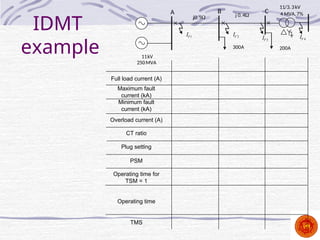
23.
IDMT
example
1
F
I
A B C
2
F
I
4
F
I
3
F
I
11kV
250MVA
11/3.3kV
4 MVA,7%
j0. 5 j 0. 4
300A 200A
Full load current (A)
Maximum fault
current (kA)
Minimum fault
current (kA)
Overload current (A)
CT ratio
Plug setting
PSM
Operating time for
TSM = 1
Operating time
TMS
#2 Fuses can provide very fast fault clearance, usually long before the first peak of the fault current. However, once the fault is cleared, the fuse needs to be replaced.
The fuse operation consists of a melting and an arcing process. Under high fault currents the narrow sections heat up and melt. Arcing occurs across the gaps until the arc voltage is so high that the current is forced to zero and the fuse link ruptures.
#3 In distribution circuits fuses may use in ground mounted structures such as a ring main unit (RMU) or they may be pole mounted. On a delta star transformer, the operation of a single phase fuse in the MV side of the transformer may result in low voltages on two phases of the LV side of the transformer. Therefore in an RMU, the fuse carries a small striker pin which will trip a three-phase switch thus disconnecting supply on all three phases.
Typical pole mounted fuse is shown in the figure. When the fuse blows, the mechanical tension of the insulation rod is lost. Therefore the rod unlatches at the top and drops, thus showing it is operated. Therefore this fuse is called drop-out expulsion fuses.
#4 The selectivity is achieved based on the time of operation of the relay. The minimum tripping time setting is given to the relay furthest away from the power source. A time delay normally called as grading margin is then added to each relay in turn, moving nearest to the source.
#5 Grading margin is allowed to take account of:
(a) Circuit breaker tripping times – It takes some time to interrupt a high fault current due to the arc produced when interrupting such a fault. This varies typically from 150 ms for an older oil CB to 50 ms for the latest vacuum or SF6 switch gear.
(b) Relay overshoot (only for electromagnetic relay) – An induction disc relay will have stored kinetic energy in the motion of the disc. This will cause an overshoot in the motion of the disc. Static relays will have energy stored in the capacitors .
(c) Errors and safety margin
If all these items are additive then for discrimination to be achieved typical time grading intervals of 0.4 - 0.5 sec are used for electromagnetic relays with oil circuit breakers and 0.25 sec for modern solid state relays which are tripping vacuum or SF6 switchgear.
#6 The fact that fault current varies with the location of the fault is used for discrimination. This means the fault current increases when fault occurs towards the source. Since relay picks up high current near the source, it operates quickly thus the disadvantage of the long time delay that occurs in the case of time graded system can be overcome.
#8 This example needs to be in the class (a) to introduce per units and (b) fault calculation using p.u. system. Then discuss the settings of relays
Selecting the relay setting based on maximum fault currents
Relay at C
Current setting 1.95
Relay will not cover the entire transformer when one generator is not in operation
Relay at B
Current setting 5.55
Relay will not cover line section BC when one generator is not in operation.
Relay at A
Current setting 8.56
Relay will not cover the entire line section when one generator is not in operation
Selecting the relay setting based on minimum fault currents
Relay at C
Current setting 1.81 kA
Relay will cover the entire transformer. Operation is satisfactory.
Relay at B
Current setting 4.58
Relay will cover the entire line section. Operation is satisfactory. Even though the relay covers part of the transformer when both generators are in operation, relay at C will operates before that as current setting of that is much smaller.
Relay at A
Current setting 6.45
Relay will cover line AB and a part of line BC when both generators are in operation. As the relays at B and C has a smaller current margin relay A might trip for a fault on line BC.
#9 The relay operates on the same basic principles as an energy metere, induction motor,
#10 When load current I increases the disk rotates against a spring load.
Two possible adjustments are:
(a) The current setting by means of plugs for values between 50 – 200% in 25% steps (typically). The 100% plug setting (PS) corresponds to the normal current rating of the relay which may be 5, 1 or 0.5 A to suit the CTs employed. On 100% tap, the disc of a 5 A relay is stable up to currents of approximately 5.0 A (However according to BS 142 – 1983, a current of 1.05 to 1.3 times rated current is required to pick up the disc movement of an electromagnetic relay). On 50% tap, the disc of the 5A relay may start at 2.5A.
(b)The operating time at a given PS can be adjusted by manually changing the initial position of the disc. This in turn adjusts the angular travel through which the disc has to move before closing the trip contacts. This is called the time multiplier setting (TMS) and can be adjusted between 0.05 and 1.0 sec (depends on the relay type).
#12 The operating time of the induction type relay depends on the amount of disc movement, i.e. the initial position of the trip contacts and the speed of rotation of the disc. The speed of the disc depends on the torque which is a function of the current.
#13 The operating characteristic of this relay is normally defined in terms of plug setting multiplier (PSM), which is the fault current as a ratio of the plug setting (PS) and TMS.
PSM shifts the curve in current axis. For example, a relay with 100:5 transformer just operates at 100 A with PS of 1.0. If the PS is changed to 2.0, then 200 A is required to just operates the relay. On the other hand only 50 A is required if PS is 0.5.
Linking to slide 13: That is at PS = 2, only half of the turns are connected to so get the same AT twice the current is required. At PS = 0.5, twice the turns are connected so only half of the current is required.
TMS reduces the operating time for a given current.
#14 Three operating characteristics are defined:
Standard curve:
Very inverse curve:
Extremely inverse curve:
#20 Discrimination by both time and current - For IDMT relays as the time of operation is inversely proportional to the fault current, that property can be used to get better discrimination.
#21 For proper operation of IDMT relay, the Plug setting multiplier and time multiplier should be properly selected.
Selecting PSM:
The relay should allow normal current as well as certain degree of overload.
The relay should be sensitive enough to respond to the smallest fault.
That is pick up or plug setting of the relay should be higher than over load current but less than minimum fault current
#23 Selecting TMS:
Start from the most remote relay and set TMS to the minimum
Select TMS of the next relay by considering the grading margin
#24 If the power angle becomes more than 90°, then torque reverses and relay trips. That is for reverse power, relay trips. Use the phasor diagram to explain the operation.
#25 If non-directional relays are applied to parallel feeders, any faults that might occur on any one line will isolate both lines.
If at the receiving end directional types relays which are operating instantaneously have been used, then
Relay B operates instantaneously, interrupting the fault feed path (2).
The relay A operates completely interrupting the fault.
One healthy line is there for power flow.
Directional IDMT relays are also used in ring main feeders.


![IEC Characteristics
Current (Multiples of Is)
0.1
1
10
100
1000
1 100
10
Operating
Time
(s)
VI
EI
SI
0.02
0.14
t TMS [ ]
1
s
PSM
13.5
t TMS [ ]
1
s
PSM
2
80
t TMS [ ]
1
s
PSM
Standard Inverse (SI)
Very Inverse (VI)
Extremely Inverse (EI)](https://image.slidesharecdn.com/l2-2-overcurrentprotection-250304094702-03528c7a/85/L2-2-Overcurrent-protection-cleaned-ppt11111111-14-320.jpg)