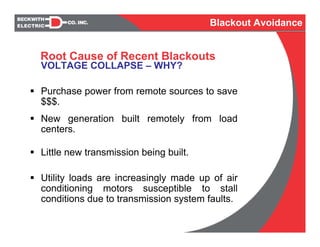
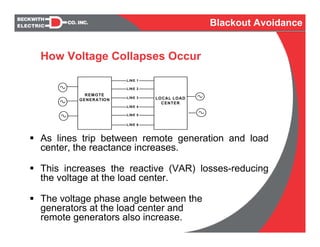
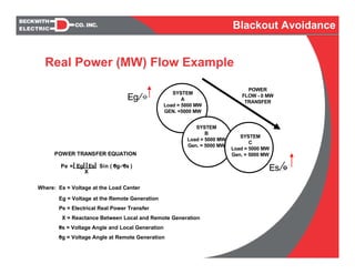
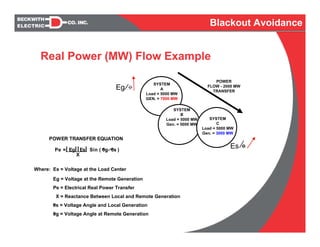
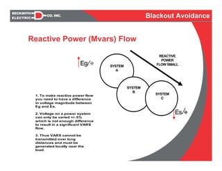
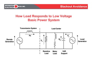
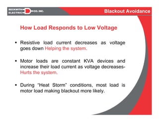
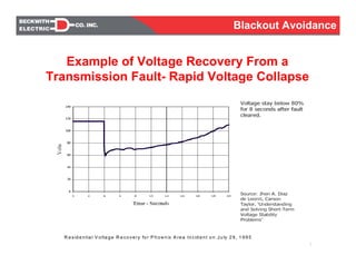
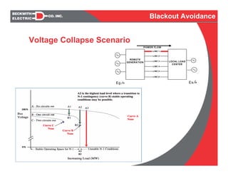
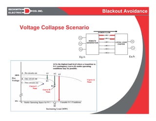
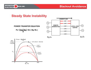
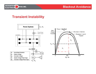
1) Voltage collapse is a major cause of recent blackouts due to increased reliance on remote generation and lack of transmission expansion. As transmission lines trip, reactive power losses increase, reducing voltage.
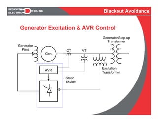
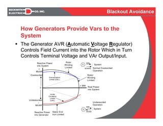
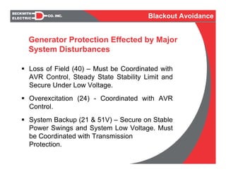
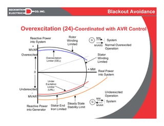
2) Generators provide reactive power (VARs) to support system voltage through their automatic voltage regulators (AVRs). During low voltage events, AVRs and generator protection systems may not be able to maintain stable operation.
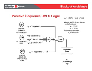
3) Undervoltage load shedding is used to prevent total system collapse by automatically removing certain loads if voltage drops below a threshold for a set time period. This helps restore the balance between generation and load.