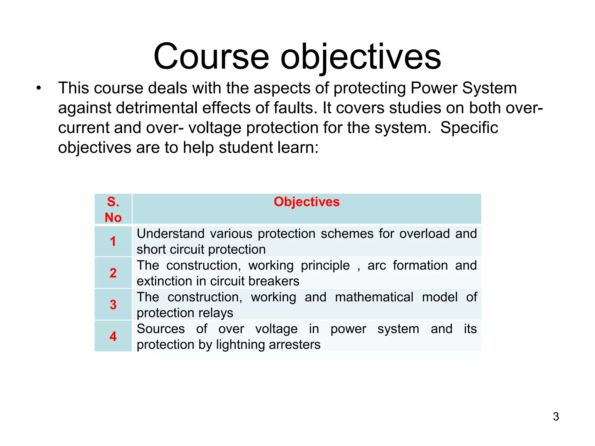
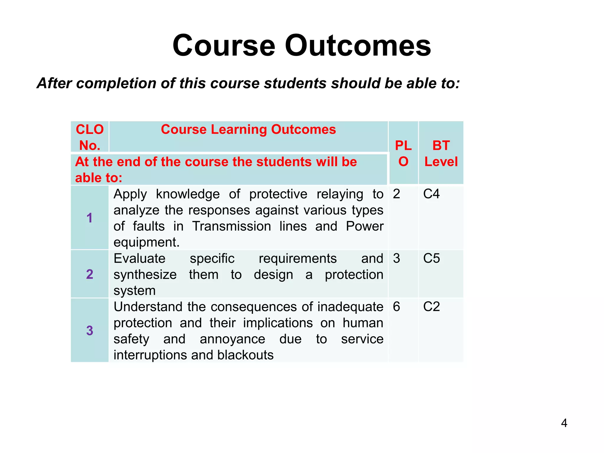
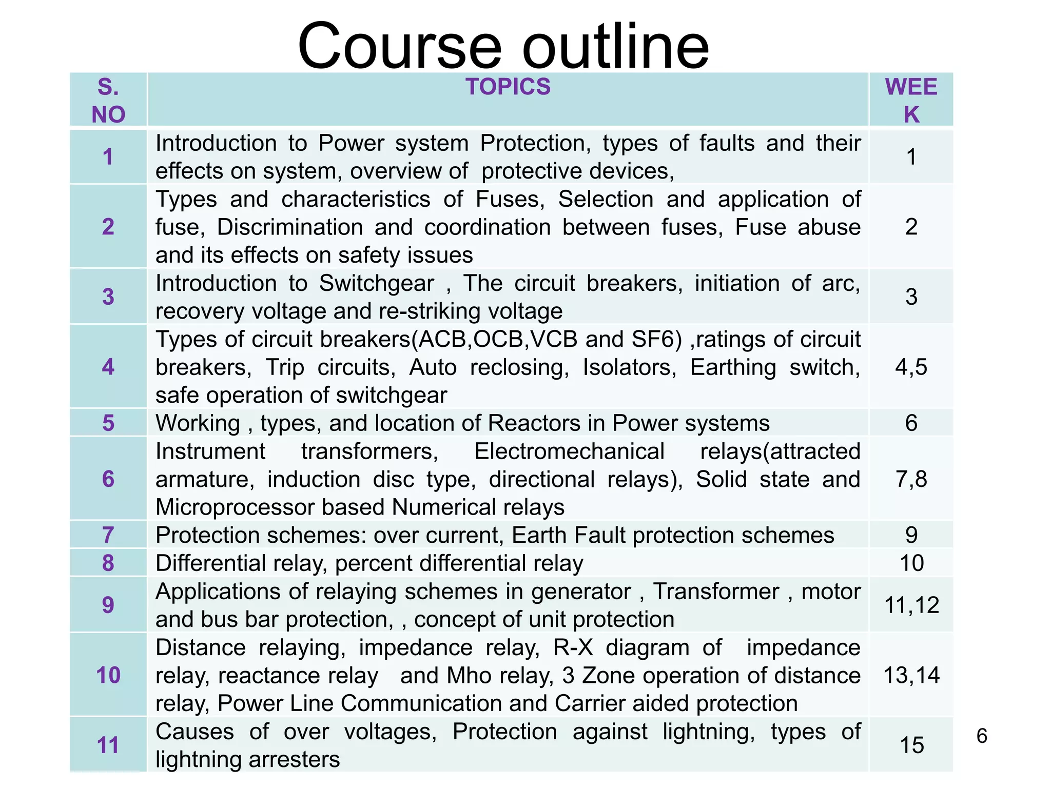
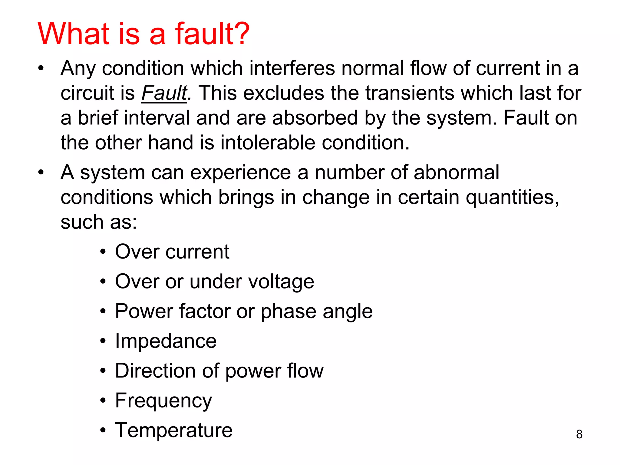
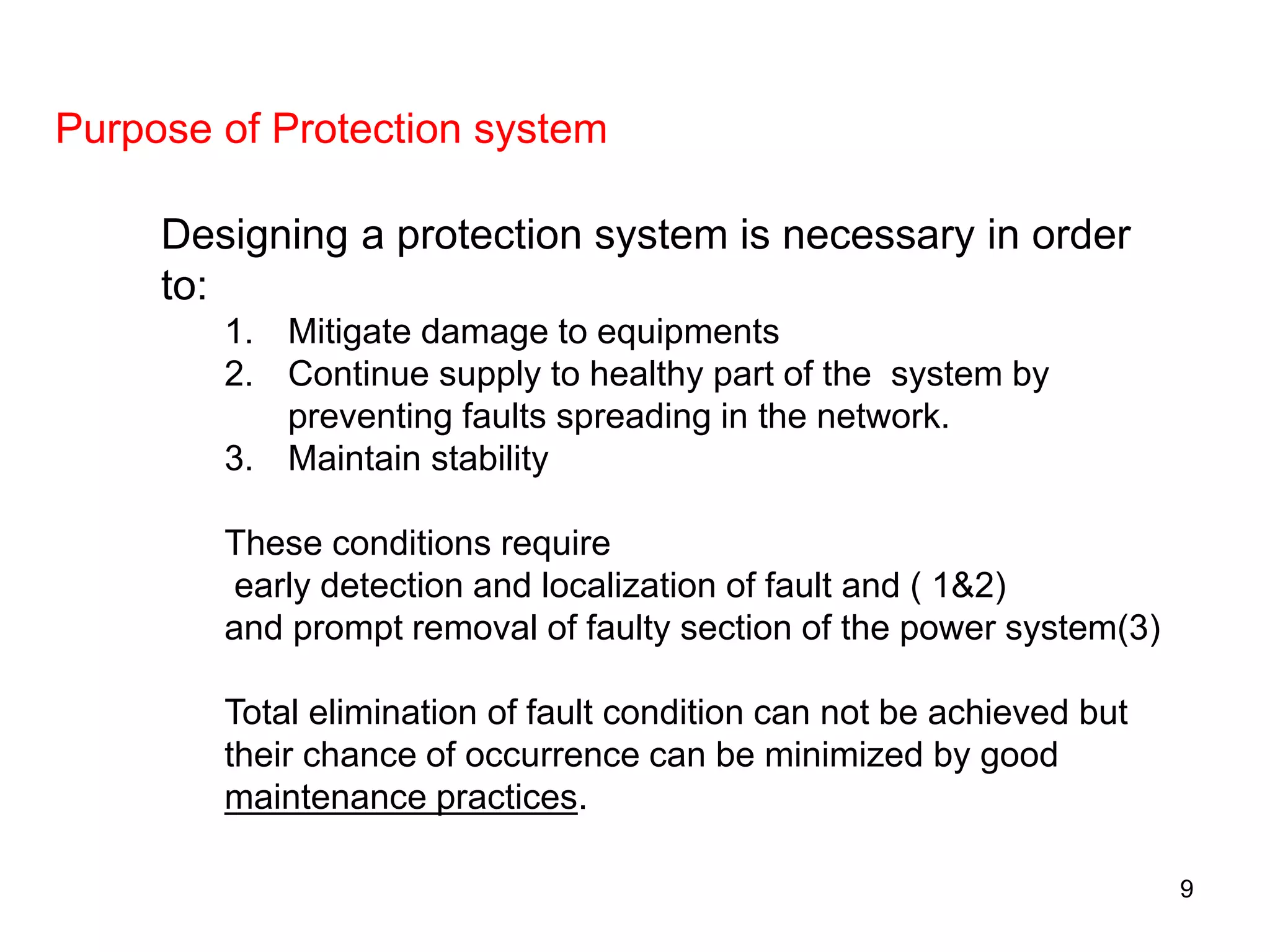
POWER SYSTEM
PROTECTION
EE-464
1
A power system which employs costly equipments such as
Generators, Transmission lines, Transformers etc. needs
to be protected against the detrimental effects of fault
conditions.
A Protection system is a safeguard against the detrimental
effects of faults.
Why protection is needed?
2
Course objectives
• This course deals with the aspects of protecting Power System
against detrimental effects of faults. It covers studies on both over-
current and over- voltage protection for the system. Specific
objectives are to help student learn:
3
S.
No
Objectives
1
Understand various protection schemes for overload and
short circuit protection
2
The construction, working principle , arc formation and
extinction in circuit breakers
3
The construction, working and mathematical model of
protection relays
4
Sources of over voltage in power system and its
protection by lightning arresters
Course Outcomes
After completion of this course students should be able to:
4
CLO
No.
Course Learning Outcomes
PL
O
BT
LevelAt the end of the course the students will be
able to:
1
Apply knowledge of protective relaying to
analyze the responses against various types
of faults in Transmission lines and Power
equipment.
2 C4
2
Evaluate specific requirements and
synthesize them to design a protection
system
3 C5
3
Understand the consequences of inadequate
protection and their implications on human
safety and annoyance due to service
interruptions and blackouts
6 C2
Text Books
1. Fundamentals of Power System Protection by Y.G.
Paithanker & S.R. Bhide, 2nd Ed., Prentice Hall, ISBN
8120321944
2. Electrical Power systems by C L Wadhwa, 4th Ed. ISBN
8122424686
3. Lecture Notes
4.Slides will be placed on LMS
5
Course outline
6
S.
NO
TOPICS WEE
K
1
Introduction to Power system Protection, types of faults and their
effects on system, overview of protective devices,
1
2
Types and characteristics of Fuses, Selection and application of
fuse, Discrimination and coordination between fuses, Fuse abuse
and its effects on safety issues
2
3
Introduction to Switchgear , The circuit breakers, initiation of arc,
recovery voltage and re-striking voltage
3
4
Types of circuit breakers(ACB,OCB,VCB and SF6) ,ratings of circuit
breakers, Trip circuits, Auto reclosing, Isolators, Earthing switch,
safe operation of switchgear
4,5
5 Working , types, and location of Reactors in Power systems 6
6
Instrument transformers, Electromechanical relays(attracted
armature, induction disc type, directional relays), Solid state and
Microprocessor based Numerical relays
7,8
7 Protection schemes: over current, Earth Fault protection schemes 9
8 Differential relay, percent differential relay 10
9
Applications of relaying schemes in generator , Transformer , motor
and bus bar protection, , concept of unit protection
11,12
10
Distance relaying, impedance relay, R-X diagram of impedance
relay, reactance relay and Mho relay, 3 Zone operation of distance
relay, Power Line Communication and Carrier aided protection
13,14
11
Causes of over voltages, Protection against lightning, types of
lightning arresters
15
INTRODUCTION
7
What is a fault?
• Any condition which interferes normal flow of current in a
circuit is Fault. This excludes the transients which last for
a brief interval and are absorbed by the system. Fault on
the other hand is intolerable condition.
• A system can experience a number of abnormal
conditions which brings in change in certain quantities,
such as:
• Over current
• Over or under voltage
• Power factor or phase angle
• Impedance
• Direction of power flow
• Frequency
• Temperature 8
Designing a protection system is necessary in order
to:
1. Mitigate damage to equipments
2. Continue supply to healthy part of the system by
preventing faults spreading in the network.
3. Maintain stability
These conditions require
early detection and localization of fault and ( 1&2)
and prompt removal of faulty section of the power system(3)
Total elimination of fault condition can not be achieved but
their chance of occurrence can be minimized by good
maintenance practices.
Purpose of Protection system
9
• While designing a protection system, proper cost-to-
benefit ratio should be considered.
• The cost of protection is considered with the cost of the
plant to be protected, but usually should not be more
than 5% of the total cost. However, if the apparatus to be
protected is of paramount importance like the generator
or major transmission line, reliability can sometimes
override the cost consideration.
10
FAULT ANALYSIS
• Accurate protection can not be achieved without properly
measuring the normal and abnormal conditions of the
system.
• Fault analysis is therefore necessary to select most
suitable protection device.
• The most common indication of fault is the sudden and
significant change in the value of current. Therefore,
over-current protection is widely used.
• Over voltage ( > 1.1 p.u) is primarily due to lightning
strokes on overhead lines. Over voltage could be either
oscillatory for a brief interval of 0.3 to 50 ms duration
( e.g., resonance) or impulsive 1.5 x 50 μs(lightning).
11
Types of Faults
active fault when actual current flows phase-to-phase
or phase to ground
• Short circuit ; either solid or through impedance
Passive fault are not faults in true sense but are
conditions when a system is overstressed beyond its
design capability
• Overload
• Over voltage (if not properly addressed may lead to over-
current condition by insulation deterioration)
• Under frequency
• Power swing
Incipient faults start as a small thing and leads to actual
fault e.g, Corona discharge, polluted insulators etc.
12
OVER CURRENT PROTECTION
Importance of Short circuit
calculations
13
Faults and their chances of occurrence
• SYMMETRICAL
FAULTS
– 3-phase faults ( 3 to 2%)
• UNSYMMETRICAL
FAULTS
– Single line to ground
fault or earth fault
(70 to 80%)
– Line to line fault
(10 to 8%)
– Double line to ground
fault
(17 to 10%)
– Open conductor fault
not common except for
LV system where fuse
blow will lead to such
condition 14
Symmetrical fault
• Represents symmetrical
( balanced) loading of the
system
– Per phase equivalent
system is used to
analyze a 3-phase
system .
3Φ fault
AC X
E
I
15
Unsymmetrical fault
• System is unbalanced
– Per phase equivalent
circuit can not be used
directly. Use of
symmetrical
components
transforms an
unbalanced system
into equivalent
balanced system
LLF
SLGF
DLGF
16
Example : A 2 bus system-
Power world simulation
slack
1.00 pu
0.3 MW
0.0 Mvar
0.3 MW
0.0 Mvar
0.3 MW
0.0 Mvar
0.3 MW
0.0 Mvar
A
MVA
A
MVA
A
MVA
A
MVA
Bus 2
Bus 1
300.0 MW
0.0 Mvar
299.4 MW
AGC ON
1 MW
17
Fault Analysis of the system
Fault at Bus-1 Fault at Bus-2
S.No Fault Type Fault
magnitude
in p.u
1 SLGF 3.056
2 LLF 3.089
3 DLGF 2.332
4 3-PHASE 3.566
S.No Fault type Fault
Magnitude
in p.u
1 SLGF 3.325
2 LLF 2.880
3 DLGF 2.223
4 3-PHASE 3.325
18
Line Fault Analysis
Fault at mid Line 1-2 cct 2
S.
No
Fault type Fault
Magnitude
in p.u
1 SLGF 2.611
2 LLF 2.802
3 DLGF 2.019
4 3-PHASE 3.236
Fault at 20% of Line 1-2
cct 2
S.
No
Fault type Fault
Magnitude
in p.u
1 SLGF 2.788
2 LLF 2.801
3 DLGF 2.133
4 3-PHASE 3.234
19

Power System Protection course - Part I

  • 1.
  • 2.
    A power systemwhich employs costly equipments such as Generators, Transmission lines, Transformers etc. needs to be protected against the detrimental effects of fault conditions. A Protection system is a safeguard against the detrimental effects of faults. Why protection is needed? 2
  • 3.
    Course objectives • Thiscourse deals with the aspects of protecting Power System against detrimental effects of faults. It covers studies on both over- current and over- voltage protection for the system. Specific objectives are to help student learn: 3 S. No Objectives 1 Understand various protection schemes for overload and short circuit protection 2 The construction, working principle , arc formation and extinction in circuit breakers 3 The construction, working and mathematical model of protection relays 4 Sources of over voltage in power system and its protection by lightning arresters
  • 4.
    Course Outcomes After completionof this course students should be able to: 4 CLO No. Course Learning Outcomes PL O BT LevelAt the end of the course the students will be able to: 1 Apply knowledge of protective relaying to analyze the responses against various types of faults in Transmission lines and Power equipment. 2 C4 2 Evaluate specific requirements and synthesize them to design a protection system 3 C5 3 Understand the consequences of inadequate protection and their implications on human safety and annoyance due to service interruptions and blackouts 6 C2
  • 5.
    Text Books 1. Fundamentalsof Power System Protection by Y.G. Paithanker & S.R. Bhide, 2nd Ed., Prentice Hall, ISBN 8120321944 2. Electrical Power systems by C L Wadhwa, 4th Ed. ISBN 8122424686 3. Lecture Notes 4.Slides will be placed on LMS 5
  • 6.
    Course outline 6 S. NO TOPICS WEE K 1 Introductionto Power system Protection, types of faults and their effects on system, overview of protective devices, 1 2 Types and characteristics of Fuses, Selection and application of fuse, Discrimination and coordination between fuses, Fuse abuse and its effects on safety issues 2 3 Introduction to Switchgear , The circuit breakers, initiation of arc, recovery voltage and re-striking voltage 3 4 Types of circuit breakers(ACB,OCB,VCB and SF6) ,ratings of circuit breakers, Trip circuits, Auto reclosing, Isolators, Earthing switch, safe operation of switchgear 4,5 5 Working , types, and location of Reactors in Power systems 6 6 Instrument transformers, Electromechanical relays(attracted armature, induction disc type, directional relays), Solid state and Microprocessor based Numerical relays 7,8 7 Protection schemes: over current, Earth Fault protection schemes 9 8 Differential relay, percent differential relay 10 9 Applications of relaying schemes in generator , Transformer , motor and bus bar protection, , concept of unit protection 11,12 10 Distance relaying, impedance relay, R-X diagram of impedance relay, reactance relay and Mho relay, 3 Zone operation of distance relay, Power Line Communication and Carrier aided protection 13,14 11 Causes of over voltages, Protection against lightning, types of lightning arresters 15
  • 7.
  • 8.
    What is afault? • Any condition which interferes normal flow of current in a circuit is Fault. This excludes the transients which last for a brief interval and are absorbed by the system. Fault on the other hand is intolerable condition. • A system can experience a number of abnormal conditions which brings in change in certain quantities, such as: • Over current • Over or under voltage • Power factor or phase angle • Impedance • Direction of power flow • Frequency • Temperature 8
  • 9.
    Designing a protectionsystem is necessary in order to: 1. Mitigate damage to equipments 2. Continue supply to healthy part of the system by preventing faults spreading in the network. 3. Maintain stability These conditions require early detection and localization of fault and ( 1&2) and prompt removal of faulty section of the power system(3) Total elimination of fault condition can not be achieved but their chance of occurrence can be minimized by good maintenance practices. Purpose of Protection system 9
  • 10.
    • While designinga protection system, proper cost-to- benefit ratio should be considered. • The cost of protection is considered with the cost of the plant to be protected, but usually should not be more than 5% of the total cost. However, if the apparatus to be protected is of paramount importance like the generator or major transmission line, reliability can sometimes override the cost consideration. 10
  • 11.
    FAULT ANALYSIS • Accurateprotection can not be achieved without properly measuring the normal and abnormal conditions of the system. • Fault analysis is therefore necessary to select most suitable protection device. • The most common indication of fault is the sudden and significant change in the value of current. Therefore, over-current protection is widely used. • Over voltage ( > 1.1 p.u) is primarily due to lightning strokes on overhead lines. Over voltage could be either oscillatory for a brief interval of 0.3 to 50 ms duration ( e.g., resonance) or impulsive 1.5 x 50 μs(lightning). 11
  • 12.
    Types of Faults activefault when actual current flows phase-to-phase or phase to ground • Short circuit ; either solid or through impedance Passive fault are not faults in true sense but are conditions when a system is overstressed beyond its design capability • Overload • Over voltage (if not properly addressed may lead to over- current condition by insulation deterioration) • Under frequency • Power swing Incipient faults start as a small thing and leads to actual fault e.g, Corona discharge, polluted insulators etc. 12
  • 13.
    OVER CURRENT PROTECTION Importanceof Short circuit calculations 13
  • 14.
    Faults and theirchances of occurrence • SYMMETRICAL FAULTS – 3-phase faults ( 3 to 2%) • UNSYMMETRICAL FAULTS – Single line to ground fault or earth fault (70 to 80%) – Line to line fault (10 to 8%) – Double line to ground fault (17 to 10%) – Open conductor fault not common except for LV system where fuse blow will lead to such condition 14
  • 15.
    Symmetrical fault • Representssymmetrical ( balanced) loading of the system – Per phase equivalent system is used to analyze a 3-phase system . 3Φ fault AC X E I 15
  • 16.
    Unsymmetrical fault • Systemis unbalanced – Per phase equivalent circuit can not be used directly. Use of symmetrical components transforms an unbalanced system into equivalent balanced system LLF SLGF DLGF 16
  • 17.
    Example : A2 bus system- Power world simulation slack 1.00 pu 0.3 MW 0.0 Mvar 0.3 MW 0.0 Mvar 0.3 MW 0.0 Mvar 0.3 MW 0.0 Mvar A MVA A MVA A MVA A MVA Bus 2 Bus 1 300.0 MW 0.0 Mvar 299.4 MW AGC ON 1 MW 17
  • 18.
    Fault Analysis ofthe system Fault at Bus-1 Fault at Bus-2 S.No Fault Type Fault magnitude in p.u 1 SLGF 3.056 2 LLF 3.089 3 DLGF 2.332 4 3-PHASE 3.566 S.No Fault type Fault Magnitude in p.u 1 SLGF 3.325 2 LLF 2.880 3 DLGF 2.223 4 3-PHASE 3.325 18
  • 19.
    Line Fault Analysis Faultat mid Line 1-2 cct 2 S. No Fault type Fault Magnitude in p.u 1 SLGF 2.611 2 LLF 2.802 3 DLGF 2.019 4 3-PHASE 3.236 Fault at 20% of Line 1-2 cct 2 S. No Fault type Fault Magnitude in p.u 1 SLGF 2.788 2 LLF 2.801 3 DLGF 2.133 4 3-PHASE 3.234 19