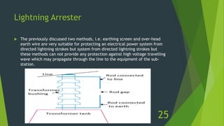
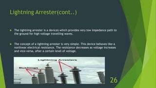
The document discusses overvoltages, defining them as voltages exceeding maximum system values and categorizing them into temporary and transient types. It elaborates on their causes—including internal factors like switching surges and external factors like lightning—and outlines methods for protection against lightning, such as earthing screens, overhead earth wires, and lightning arresters. Additionally, it includes review questions related to the types and causes of overvoltages, as well as concepts like arcing ground and surge absorbers.
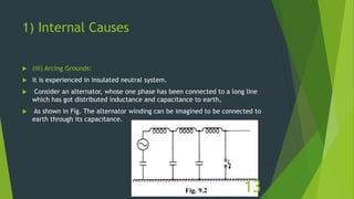
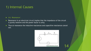


![protection of transmission lines[distance relay protection scheme]](https://cdn.slidesharecdn.com/ss_thumbnails/os-exe3-23-may2011-sr-i-776s21tr-lineprotection-120425095503-phpapp02-thumbnail.jpg?width=640&height=640&fit=bounds)


