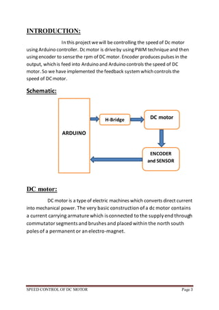
SPEED CONTROL OF DC MOTOR Page 1
International Islamic University
Islamabad
CONTROL SYSTEM LAB PROJECT
SPEED CONTROL OF DC MOTOR
Group Members:
Mafaz Ahmed 1882-F12D
Rafi Uzman 1891-F12D
Submitted To:
Sir Muhammad Asad
SPEED CONTROL OF DC MOTOR Page 2
TABLE OF CONTENTS Page
1. Introduction …………………………………………………….(3)
2. Schematic …………………………………………………….(3)
3. DC MOTOR …………………………………………………….(3)
 Types
4. Arduino …………………………………………………….(4)
 Featured
5. PCB design …………………………………………………….(5)
6. H-Bridge …………………………………………………….(6)
7. Optocoupler ……………….…………………………………….(7)
8. Rotary Encoder ………………………….………………………….(8)
9. Code …………………………………………………….(8)
10.Conclusion …………………………………………..……….(10)
11.References …………………………………………………….(10)
SPEED CONTROL OF DC MOTOR Page 3
INTRODUCTION:
In this project wewill be controlling the speed of Dc motor
using Arduino controller. Dc motor is driveby using PWM technique and then
using encoder to sensethe rpm of DC motor. Encoder produces pulses in the
output, which is feed into Arduino and Arduino controls the speed of DC
motor. So we have implemented the feedback systemwhich controls the
speed of DCmotor.
Schematic:
DC motor:
DC motor is a type of electric machines which converts direct current
into mechanical power. The very basic construction ofa dc motor contains
a current carrying armature which is connected to the supplyend through
commutatorsegments and brushes and placed within the north south
poles of a permanent or an electro-magnet.
ARDUINO
DC motor
ENCODER
and SENSOR
H-Bridge
SPEED CONTROL OF DC MOTOR Page 4
TYPES:
There are three types of DC motor,
1. ShuntDC motor
2. Series DC motor
3. Compound DC motor
Arduino:
Arduino is an open sourcecomputer hardware. An Arduino board
consists of an Atmel 8-, 16- or 32-bit AVRmicrocontroller with complementary
components that facilitate programming and incorporation into other circuits.
Ithas 14 digital input/output pins (of which 6 can be used as PWMoutputs), 6
analog inputs, a 16 MHz ceramic resonator, a USB connection, a power jack, an
ICSP header, and a resetbutton. Itcontains everything needed to supportthe
microcontroller; simply connect it to a computer with a USB cable or power it
with AC-to-DC adapter or battery.
SPEED CONTROL OF DC MOTOR Page 5
FEATURES:
Microcontroller ATmega8
Operating Voltage 5V
InputVoltage (recommended) 7-12V
InputVoltage (limits) 6-20V
Digital I/O Pins 14 (of which 6 providePWMoutput)
Analog InputPins 6
DC Currentper I/O Pin 40 mA
DC Currentfor 3.3V Pin 50 mA
EEPROM 1 KB
Clock Speed 16 MHz
PCB design:
SPEED CONTROL OF DC MOTOR Page 6
H-Bridge (L293D):
An H bridgeis an electronic circuit that enables a
voltage to be applied across a load in either direction. These circuits are often
used in robotics and other applications to allow DC motors to run forwards and
backwards.
L293D is a dual H-bridgemotor driver integrated circuit (IC). Motor drivers act
as current amplifiers since they take a low-currentcontrolsignaland providea
higher-currentsignal. This higher current signalis used to drivethe motors.
L293D contains two inbuilt H-bridgedriver circuits. In its common mode of
operation, two DC motors can be driven simultaneously, both in forward and
reversedirection. The motor operations of two motors can be controlled by
input logic at pins 2 & 7 and 10 & 15. Inputlogic 00 or 11 will stop the
corresponding motor. Logic 01 and 10 will rotate it in clockwiseand
anticlockwisedirections, respectively. Enable pins 1 and 9 (corresponding to
the two motors) mustbe high for motors to start operating. When an enable
input is high, the associated driver gets enabled. As a result, the outputs
become active and work in phase with their inputs. Similarly, when the enable
input is low, that driver is disabled, and their outputs are off and in the high-
impedance state.
SPEED CONTROL OF DC MOTOR Page 7
Optocoupler:
An optical coupler, also called opto-isolator,
optocoupler, optocoupler, photocoupler or optical isolator, is a passiveoptical
component that can combine or split transmission data (optical power) from
optical fibers. Itis an electronic device which is designed to transfer electrical
signals by using light waves in order to providecoupling with electrical
isolation between its input and output. The main purposeof an optocoupler is
to prevent rapidly changing voltages or high voltages on one side of a circuit
fromdistorting transmissions or damaging components on the other side of
the circuit.
SPEED CONTROL OF DC MOTOR Page 8
Rotary Encoder:
A rotary encoder is an electro-mechanical device that
converts the angular position or motion of a shaftor axle to an analog or digital
code. Our encoder is self-made which is attach to the motor.
CODE:
float rev=0;
int rpm;
int prpm=1100;
int dcyl=155;
int oldtime=0;
int time;
void isr() //interruptservice routine
{rev++;
}
void setup()
{attachInterrupt(0,isr,FALLING); //attaching the interrupt
pinMode(9, OUTPUT);
pinMode(8, OUTPUT);
pinMode(7, OUTPUT);
}void loop()
{
delay(2000);
detachInterrupt(0); //detaches the interrupt
time=millis()-oldtime; //finds the time
SPEED CONTROL OF DC MOTOR Page 9
rpm=(rev/(2*time))*60000; //calculates rpm
oldtime=millis(); //saves the currenttime
rev=0;
digitalWrite(7, LOW);
digitalWrite(8, HIGH);
if(rpm>(prpm-10 ) && rpm<(prpm+10))
{dcyl=dcyl;}
else if(rpm>prpm)
{ if (dcyl>154)
dcyl-=5;}
else if(rpm<prpm)
{ if (dcyl<251)
dcyl+=5;}
else
dcyl=dcyl;
analogWrite(9, dcyl);
//sets the desired speed
//finds the duty cycle %
attachInterrupt(0,isr,FALLING);
delay(200);
}
SPEED CONTROL OF DC MOTOR Page 10
Conclusion:
We haveimplemented a feedback control of DCmotor. When
Speed changes, sensor (auto coupler) output changes (pulses). Fromthe pulses
Arduino detects change of speed, and tries to minimize it by increasing the
duty cycle.
REFERENCES:
http://en.wikipedia.org/wiki/Arduino
http://www.electrical4u.com/working-or-operating-principle-of-dc-motor/
http://www.arduino.cc/en/Main/ArduinoBoardUno
https://www.futureelectronics.com/en/optoelectronics/optocouplers.aspx

Speed Control of DC Motor

  • 1.
    SPEED CONTROL OFDC MOTOR Page 1 International Islamic University Islamabad CONTROL SYSTEM LAB PROJECT SPEED CONTROL OF DC MOTOR Group Members: Mafaz Ahmed 1882-F12D Rafi Uzman 1891-F12D Submitted To: Sir Muhammad Asad
  • 2.
    SPEED CONTROL OFDC MOTOR Page 2 TABLE OF CONTENTS Page 1. Introduction …………………………………………………….(3) 2. Schematic …………………………………………………….(3) 3. DC MOTOR …………………………………………………….(3)  Types 4. Arduino …………………………………………………….(4)  Featured 5. PCB design …………………………………………………….(5) 6. H-Bridge …………………………………………………….(6) 7. Optocoupler ……………….…………………………………….(7) 8. Rotary Encoder ………………………….………………………….(8) 9. Code …………………………………………………….(8) 10.Conclusion …………………………………………..……….(10) 11.References …………………………………………………….(10)
  • 3.
    SPEED CONTROL OFDC MOTOR Page 3 INTRODUCTION: In this project wewill be controlling the speed of Dc motor using Arduino controller. Dc motor is driveby using PWM technique and then using encoder to sensethe rpm of DC motor. Encoder produces pulses in the output, which is feed into Arduino and Arduino controls the speed of DC motor. So we have implemented the feedback systemwhich controls the speed of DCmotor. Schematic: DC motor: DC motor is a type of electric machines which converts direct current into mechanical power. The very basic construction ofa dc motor contains a current carrying armature which is connected to the supplyend through commutatorsegments and brushes and placed within the north south poles of a permanent or an electro-magnet. ARDUINO DC motor ENCODER and SENSOR H-Bridge
  • 4.
    SPEED CONTROL OFDC MOTOR Page 4 TYPES: There are three types of DC motor, 1. ShuntDC motor 2. Series DC motor 3. Compound DC motor Arduino: Arduino is an open sourcecomputer hardware. An Arduino board consists of an Atmel 8-, 16- or 32-bit AVRmicrocontroller with complementary components that facilitate programming and incorporation into other circuits. Ithas 14 digital input/output pins (of which 6 can be used as PWMoutputs), 6 analog inputs, a 16 MHz ceramic resonator, a USB connection, a power jack, an ICSP header, and a resetbutton. Itcontains everything needed to supportthe microcontroller; simply connect it to a computer with a USB cable or power it with AC-to-DC adapter or battery.
  • 5.
    SPEED CONTROL OFDC MOTOR Page 5 FEATURES: Microcontroller ATmega8 Operating Voltage 5V InputVoltage (recommended) 7-12V InputVoltage (limits) 6-20V Digital I/O Pins 14 (of which 6 providePWMoutput) Analog InputPins 6 DC Currentper I/O Pin 40 mA DC Currentfor 3.3V Pin 50 mA EEPROM 1 KB Clock Speed 16 MHz PCB design:
  • 6.
    SPEED CONTROL OFDC MOTOR Page 6 H-Bridge (L293D): An H bridgeis an electronic circuit that enables a voltage to be applied across a load in either direction. These circuits are often used in robotics and other applications to allow DC motors to run forwards and backwards. L293D is a dual H-bridgemotor driver integrated circuit (IC). Motor drivers act as current amplifiers since they take a low-currentcontrolsignaland providea higher-currentsignal. This higher current signalis used to drivethe motors. L293D contains two inbuilt H-bridgedriver circuits. In its common mode of operation, two DC motors can be driven simultaneously, both in forward and reversedirection. The motor operations of two motors can be controlled by input logic at pins 2 & 7 and 10 & 15. Inputlogic 00 or 11 will stop the corresponding motor. Logic 01 and 10 will rotate it in clockwiseand anticlockwisedirections, respectively. Enable pins 1 and 9 (corresponding to the two motors) mustbe high for motors to start operating. When an enable input is high, the associated driver gets enabled. As a result, the outputs become active and work in phase with their inputs. Similarly, when the enable input is low, that driver is disabled, and their outputs are off and in the high- impedance state.
  • 7.
    SPEED CONTROL OFDC MOTOR Page 7 Optocoupler: An optical coupler, also called opto-isolator, optocoupler, optocoupler, photocoupler or optical isolator, is a passiveoptical component that can combine or split transmission data (optical power) from optical fibers. Itis an electronic device which is designed to transfer electrical signals by using light waves in order to providecoupling with electrical isolation between its input and output. The main purposeof an optocoupler is to prevent rapidly changing voltages or high voltages on one side of a circuit fromdistorting transmissions or damaging components on the other side of the circuit.
  • 8.
    SPEED CONTROL OFDC MOTOR Page 8 Rotary Encoder: A rotary encoder is an electro-mechanical device that converts the angular position or motion of a shaftor axle to an analog or digital code. Our encoder is self-made which is attach to the motor. CODE: float rev=0; int rpm; int prpm=1100; int dcyl=155; int oldtime=0; int time; void isr() //interruptservice routine {rev++; } void setup() {attachInterrupt(0,isr,FALLING); //attaching the interrupt pinMode(9, OUTPUT); pinMode(8, OUTPUT); pinMode(7, OUTPUT); }void loop() { delay(2000); detachInterrupt(0); //detaches the interrupt time=millis()-oldtime; //finds the time
  • 9.
    SPEED CONTROL OFDC MOTOR Page 9 rpm=(rev/(2*time))*60000; //calculates rpm oldtime=millis(); //saves the currenttime rev=0; digitalWrite(7, LOW); digitalWrite(8, HIGH); if(rpm>(prpm-10 ) && rpm<(prpm+10)) {dcyl=dcyl;} else if(rpm>prpm) { if (dcyl>154) dcyl-=5;} else if(rpm<prpm) { if (dcyl<251) dcyl+=5;} else dcyl=dcyl; analogWrite(9, dcyl); //sets the desired speed //finds the duty cycle % attachInterrupt(0,isr,FALLING); delay(200); }
  • 10.
    SPEED CONTROL OFDC MOTOR Page 10 Conclusion: We haveimplemented a feedback control of DCmotor. When Speed changes, sensor (auto coupler) output changes (pulses). Fromthe pulses Arduino detects change of speed, and tries to minimize it by increasing the duty cycle. REFERENCES: http://en.wikipedia.org/wiki/Arduino http://www.electrical4u.com/working-or-operating-principle-of-dc-motor/ http://www.arduino.cc/en/Main/ArduinoBoardUno https://www.futureelectronics.com/en/optoelectronics/optocouplers.aspx