This document discusses overcurrent protection and different types of overcurrent relays. It describes the causes and effects of overcurrent, and introduces overcurrent protection using fuses, circuit breakers and overcurrent relays. It explains the operating principles of different types of overcurrent relays including attracted armature, definite time, and inverse definite minimum time (IDMT) relays. Examples are provided to illustrate how to select settings for IDMT relays in a power system to achieve coordinated overcurrent protection.


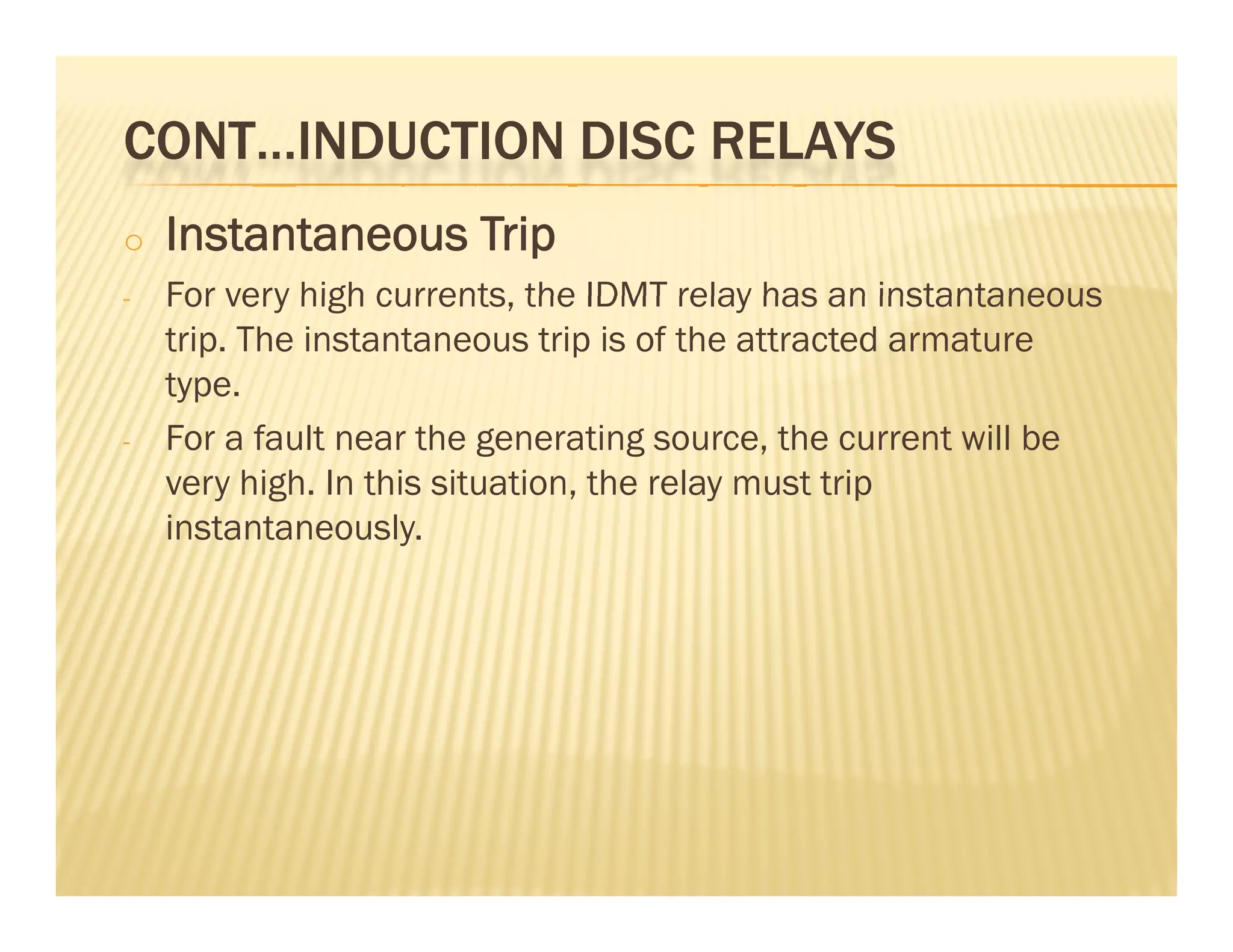


![FAULT AT C (PRIMARY)
FAULT AT C (PRIMARY)
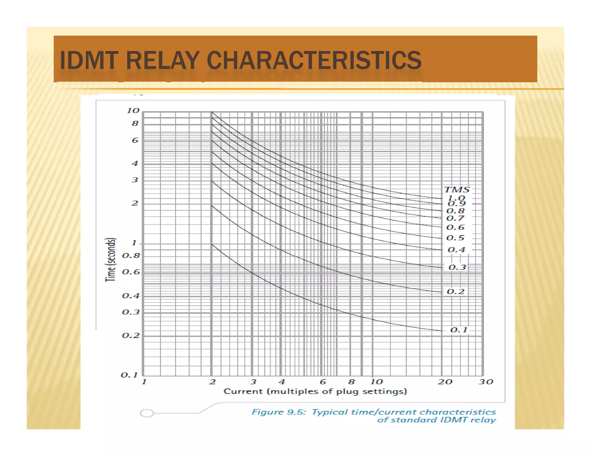
Step 5: Find the TMS from the IDMT graph
Step 5: Find the TMS from the IDMT graph
, 0.1
T M S F rom curve T M S
TMS also can obtain by formula if not state refer to the IDMT characteristics
Step 6: Conclude the final setting at relay
Step 6: Conclude the final setting at relay
Re [ 100%, 0.1]
Setting at lay C PS TMS
](https://image.slidesharecdn.com/3overcurrentprotection-230622141739-5f446566/75/3_Overcurrent-Protection-pdf-22-2048.jpg)


![FAULT AT C (BACK UP)
FAULT AT C (BACK UP)
Step 5: Find the TMS from the IDMT graph
Step 5: Find the TMS from the IDMT graph
, 0.3
TMS Fromcurve TMS
TMS also can obtain by formula if not state refer to the IDMT characteristics
Step 6: Conclude the final setting at relay
Step 6: Conclude the final setting at relay
Re [ 100%, 0.3]
Setting at lay B PS TMS
](https://image.slidesharecdn.com/3overcurrentprotection-230622141739-5f446566/75/3_Overcurrent-Protection-pdf-25-2048.jpg)


![FAULT AT B (BACK UP)
FAULT AT B (BACK UP)
Step 5: Find the TMS from the IDMT graph
Step 5: Find the TMS from the IDMT graph
, 0.4
TMS Fromcurve TMS
TMS also can obtain by formula if not state refer to the IDMT characteristics
Step 6: Conclude the final setting at relay
Step 6: Conclude the final setting at relay
]
4
.
0
%,
100
[
TMS
PS
A
relay
for
Setting ]
,
[
y
f
g](https://image.slidesharecdn.com/3overcurrentprotection-230622141739-5f446566/75/3_Overcurrent-Protection-pdf-30-2048.jpg)

![SOLUTION
%
48
100
96
PS
Relay C (Fault at C)
%
50
%
48
100
5
5
200
PS
PS
25
.
19
5
5
200
5
.
0
1925
PSM
14
0
23
.
0
5
s
tope
1
0
23
.
0
298
.
2
1
25
.
19
14
.
0
02
.
0
TMS
tchar
]
1
.
0
%,
50
[
Re
1
.
0
298
.
2
TMS
PS
A
lay
for
Setting
TMS](https://image.slidesharecdn.com/3overcurrentprotection-230622141739-5f446566/75/3_Overcurrent-Protection-pdf-32-2048.jpg)
![RELAY B (FAULT AT C)
%
49
100
300
148
PS
83
12
1925
%
50
300
PSM
PS
73
.
0
5
.
0
23
.
0
83
.
12
5
5
300
5
.
0
s
t
PSM
67
.
2
1
83
.
12
14
.
0
73
.
0
5
.
0
23
.
0
02
.
0
t
s
t
char
ope
Setting for Relay B =
27
.
0
67
.
2
73
.
0
TMS
[PS = 50%, TMS = 0.27]](https://image.slidesharecdn.com/3overcurrentprotection-230622141739-5f446566/75/3_Overcurrent-Protection-pdf-33-2048.jpg)

![RELAY A (FAULT AT B)
%
84
100
300
252
PS
2975
%
100
300
PS
92
.
9
5
5
300
1
2975
PSM
98
.
2
1
92
.
9
14
.
0
02
.
0
tchar
37
.
0
11
.
1
11
.
1
5
.
0
61
.
0
TMS
s
tope
Setting for Relay A =
[PS = 100%, TMS = 0.37]
98
.
2](https://image.slidesharecdn.com/3overcurrentprotection-230622141739-5f446566/75/3_Overcurrent-Protection-pdf-35-2048.jpg)