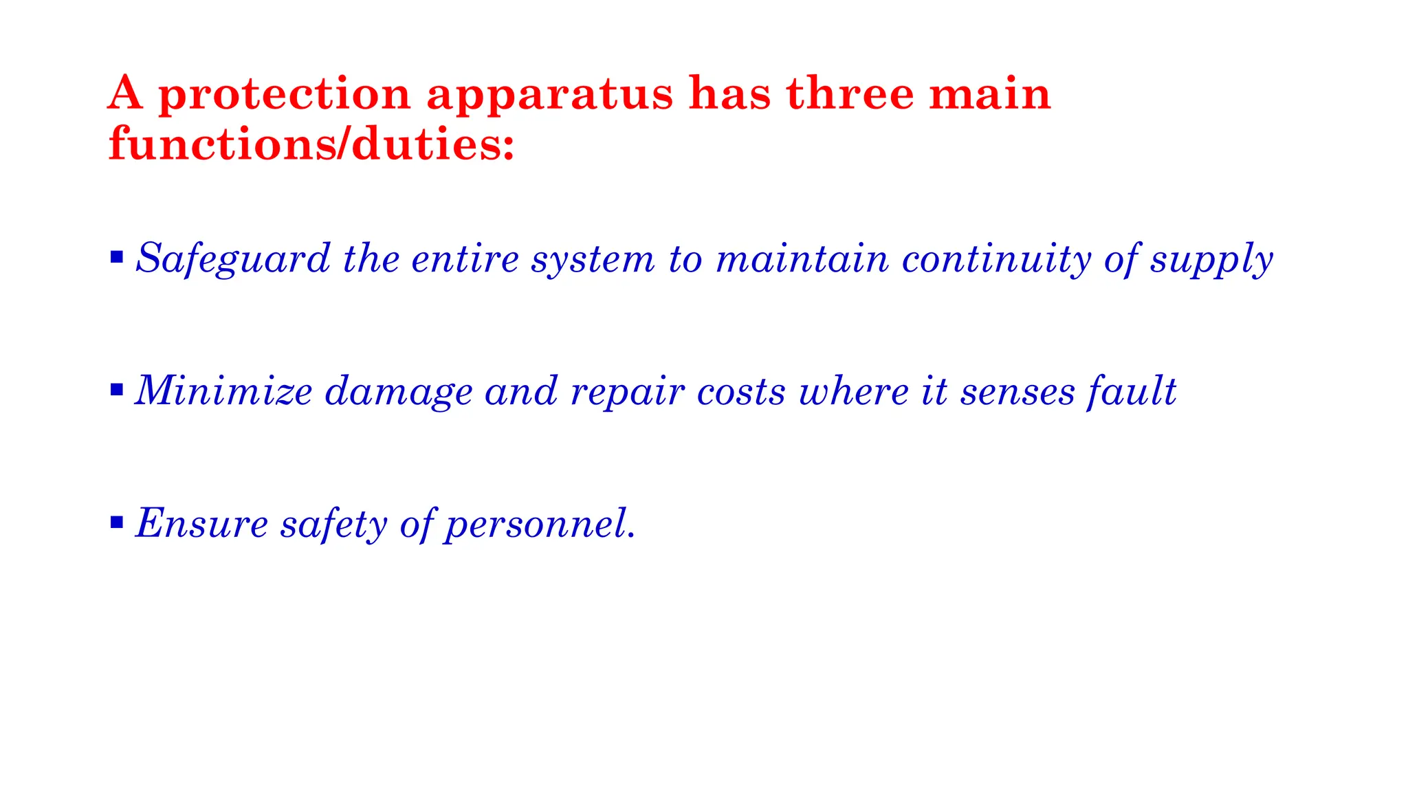
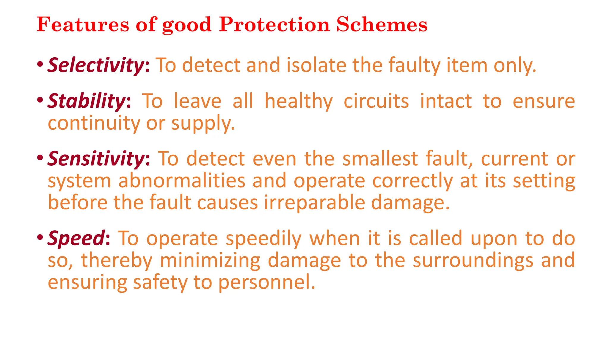
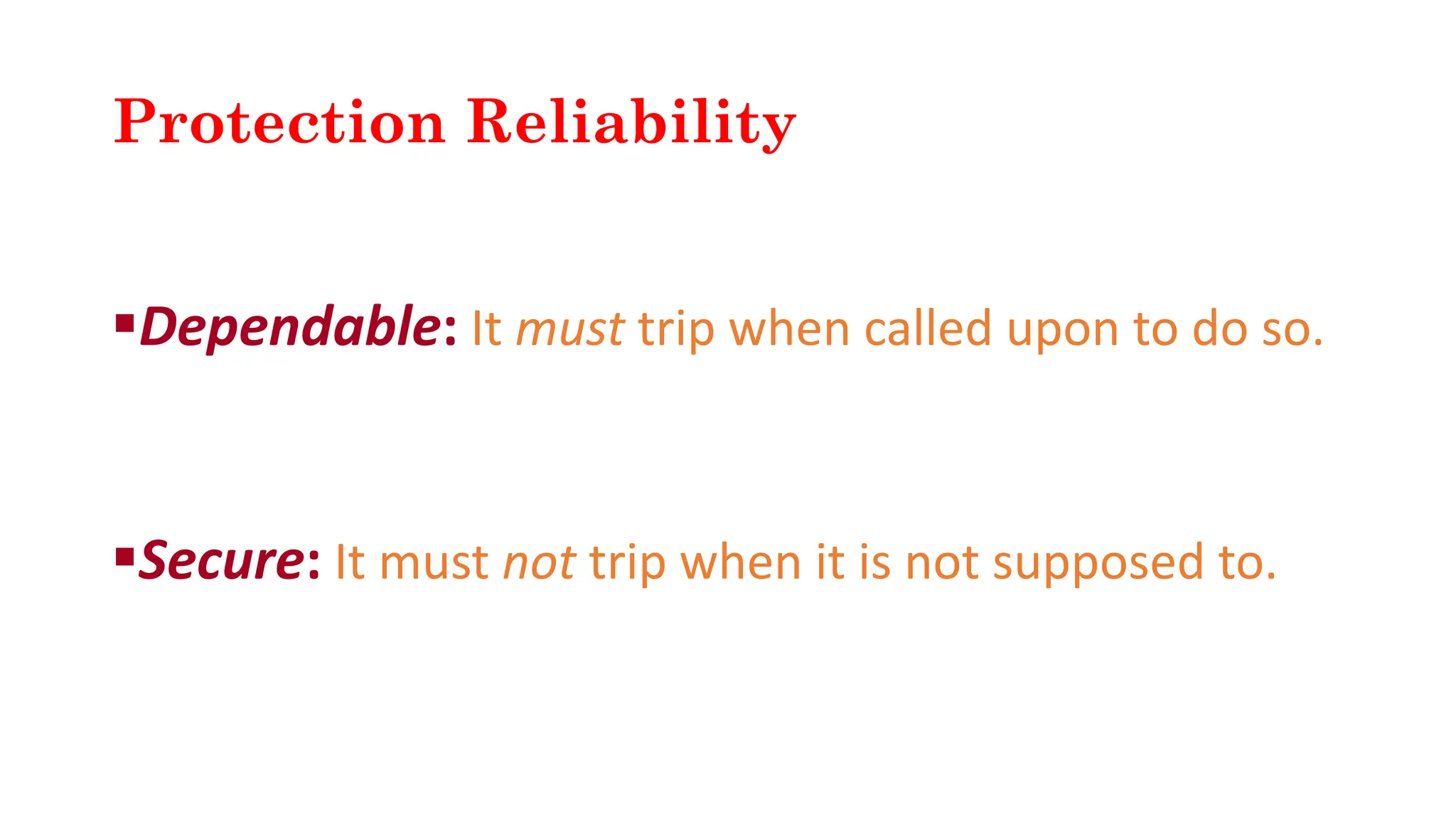
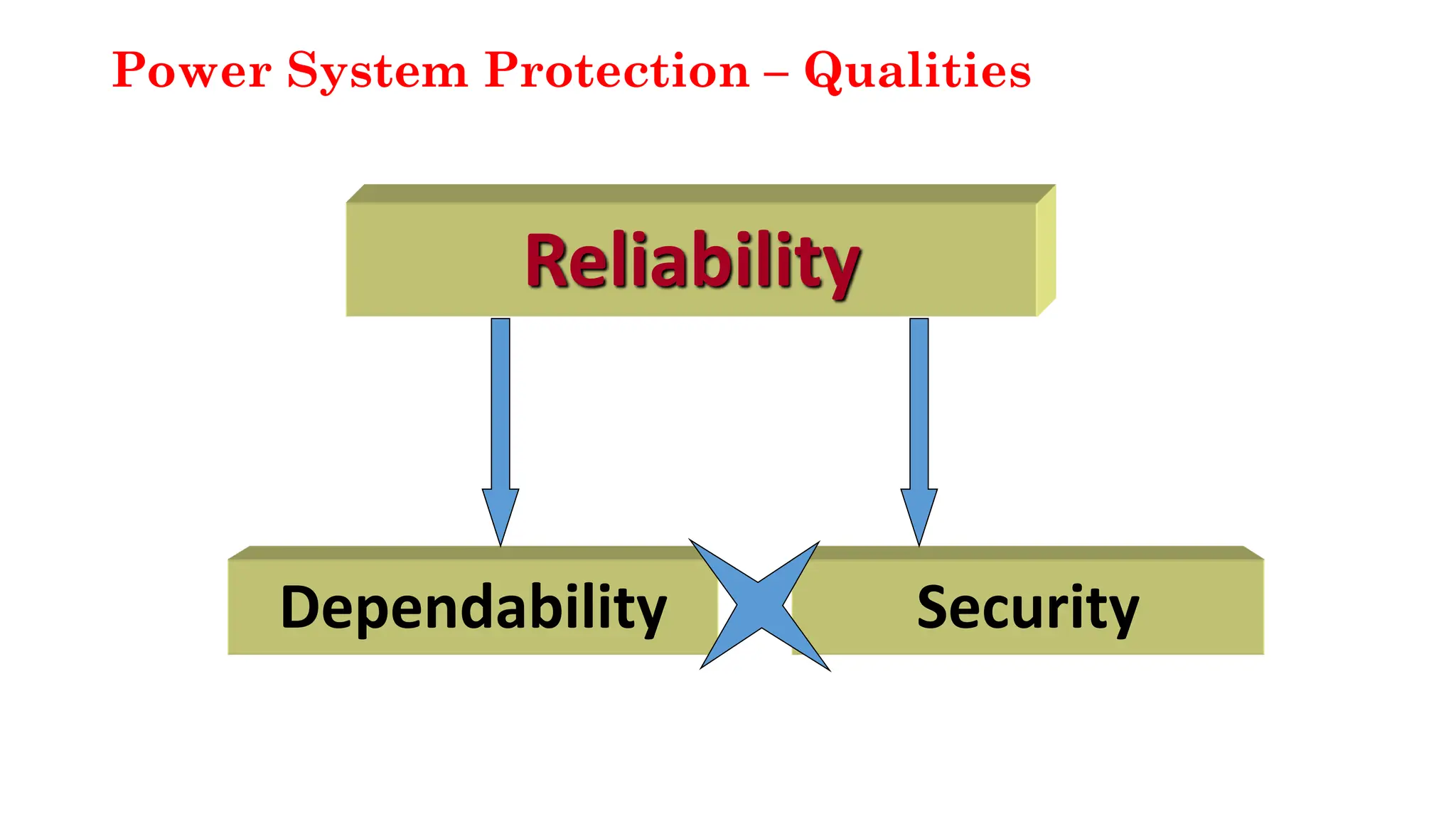
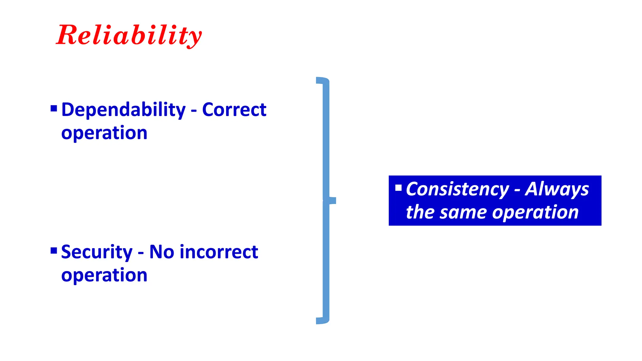
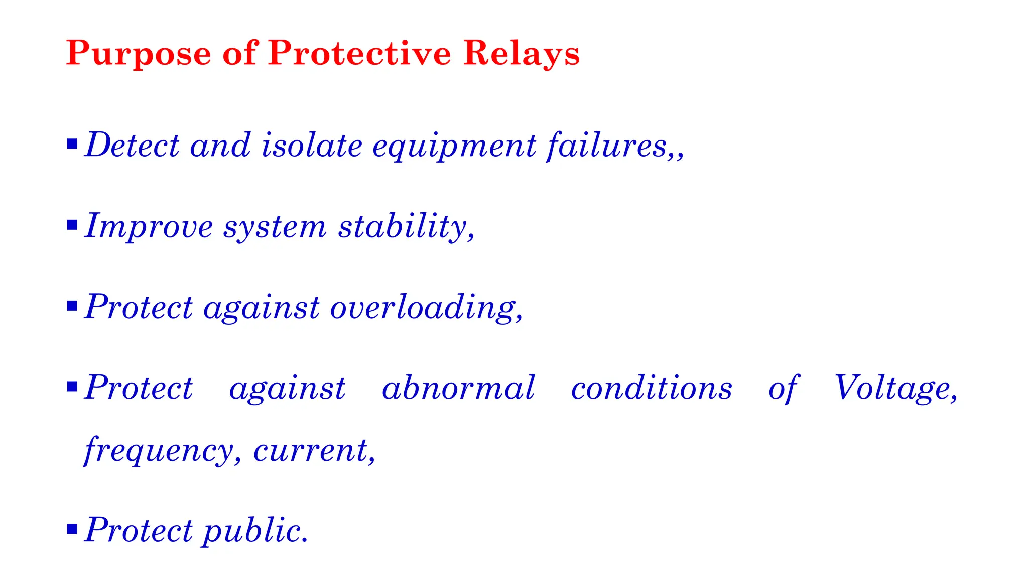
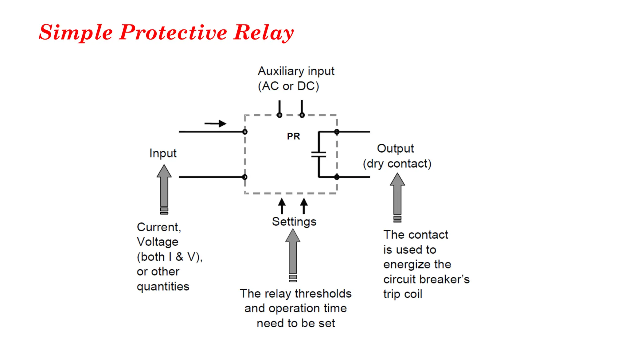
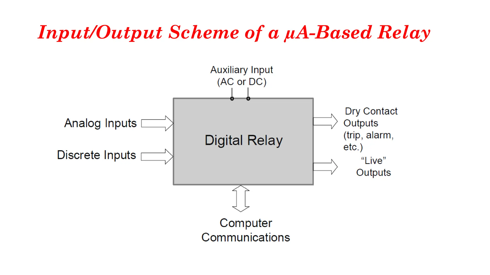
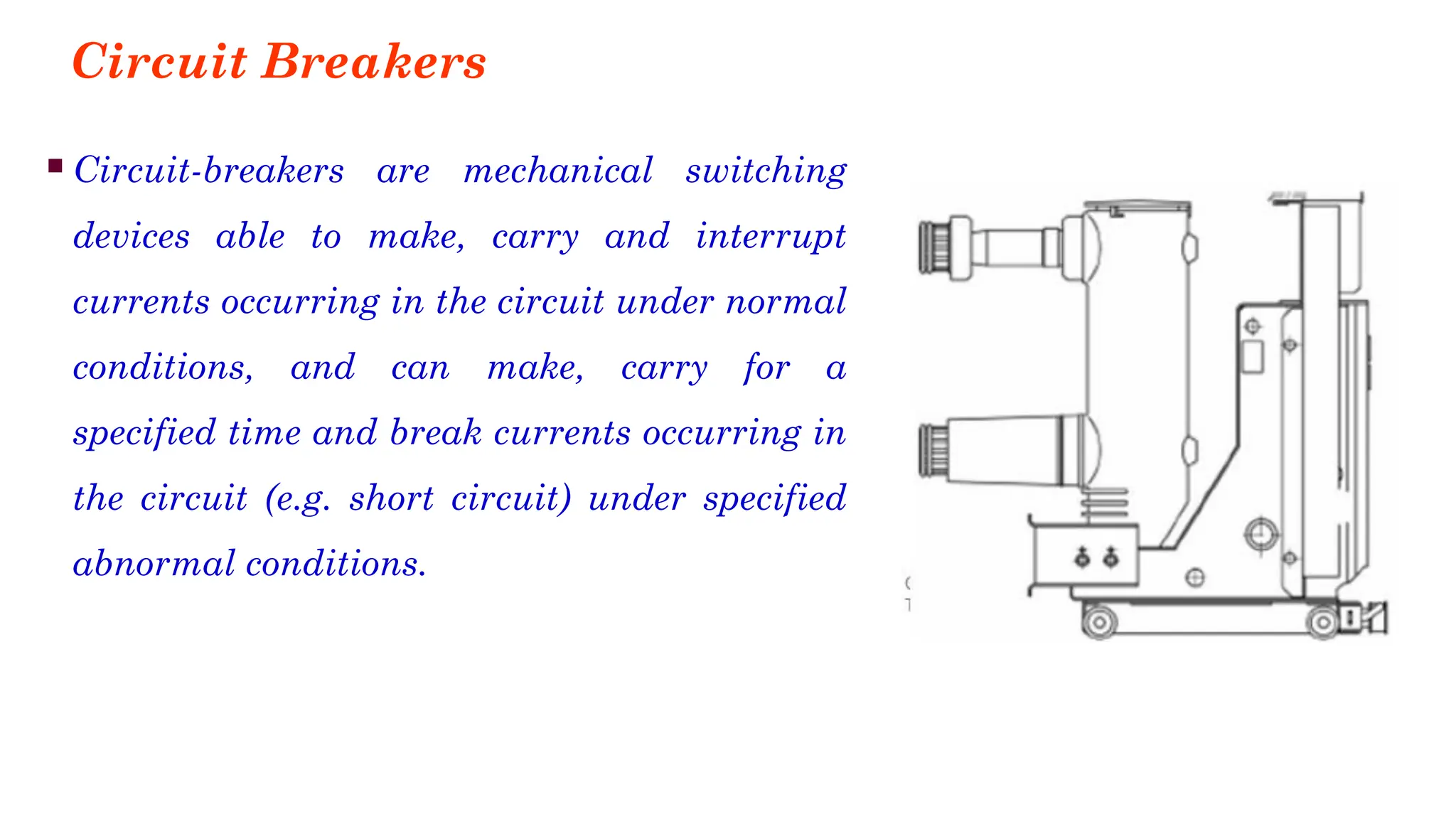
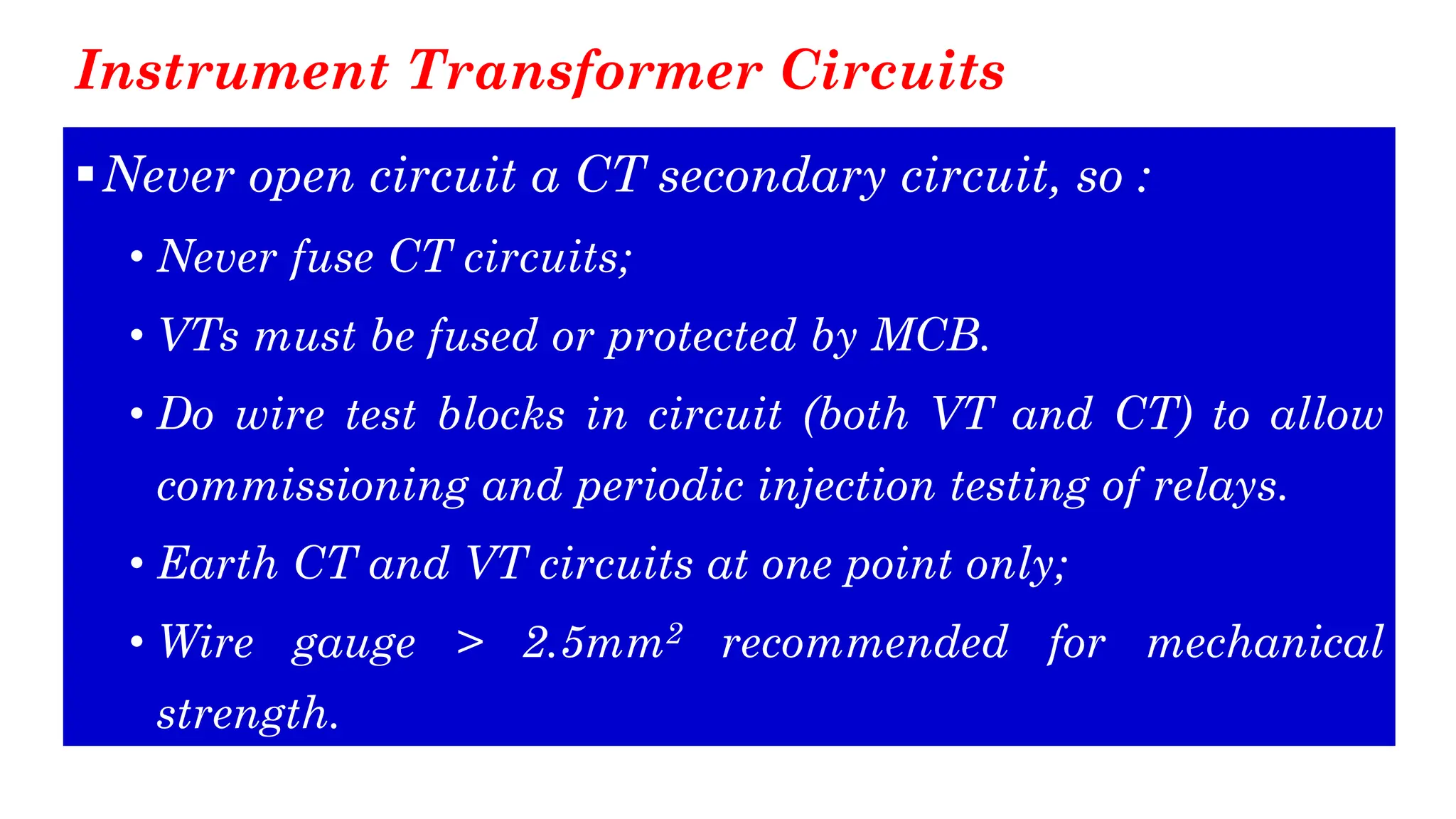
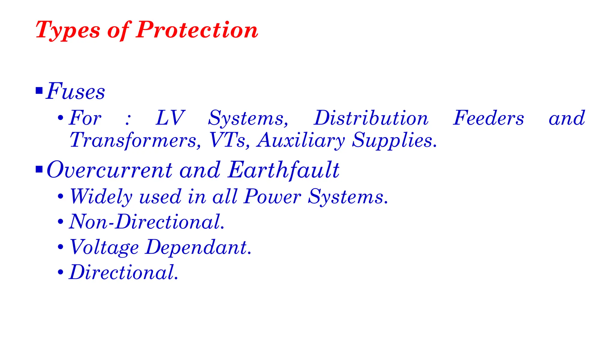
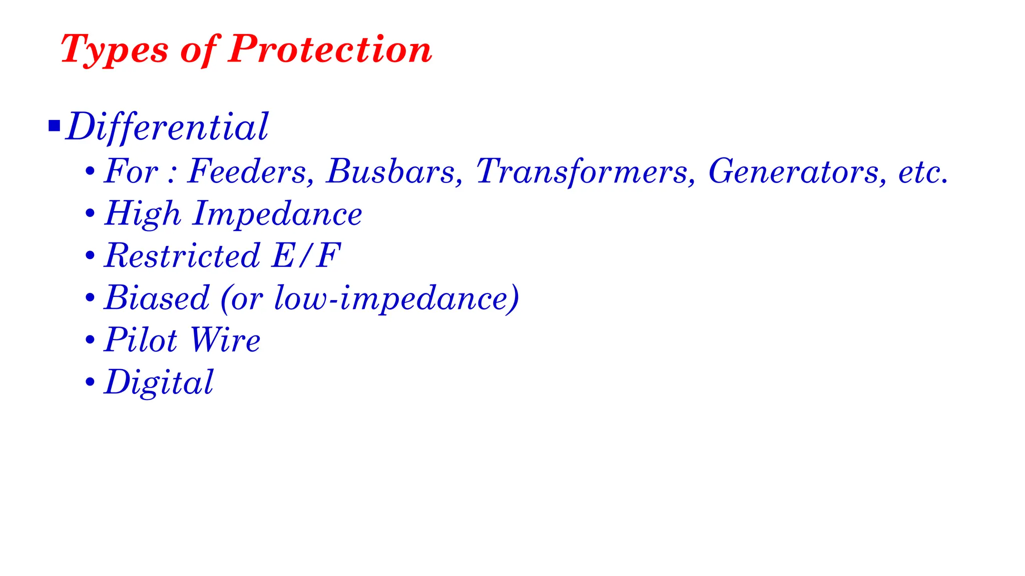
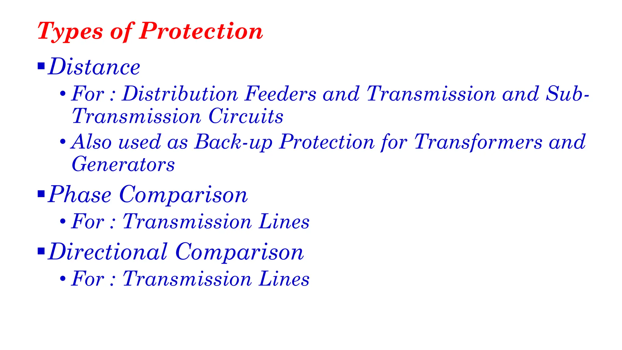
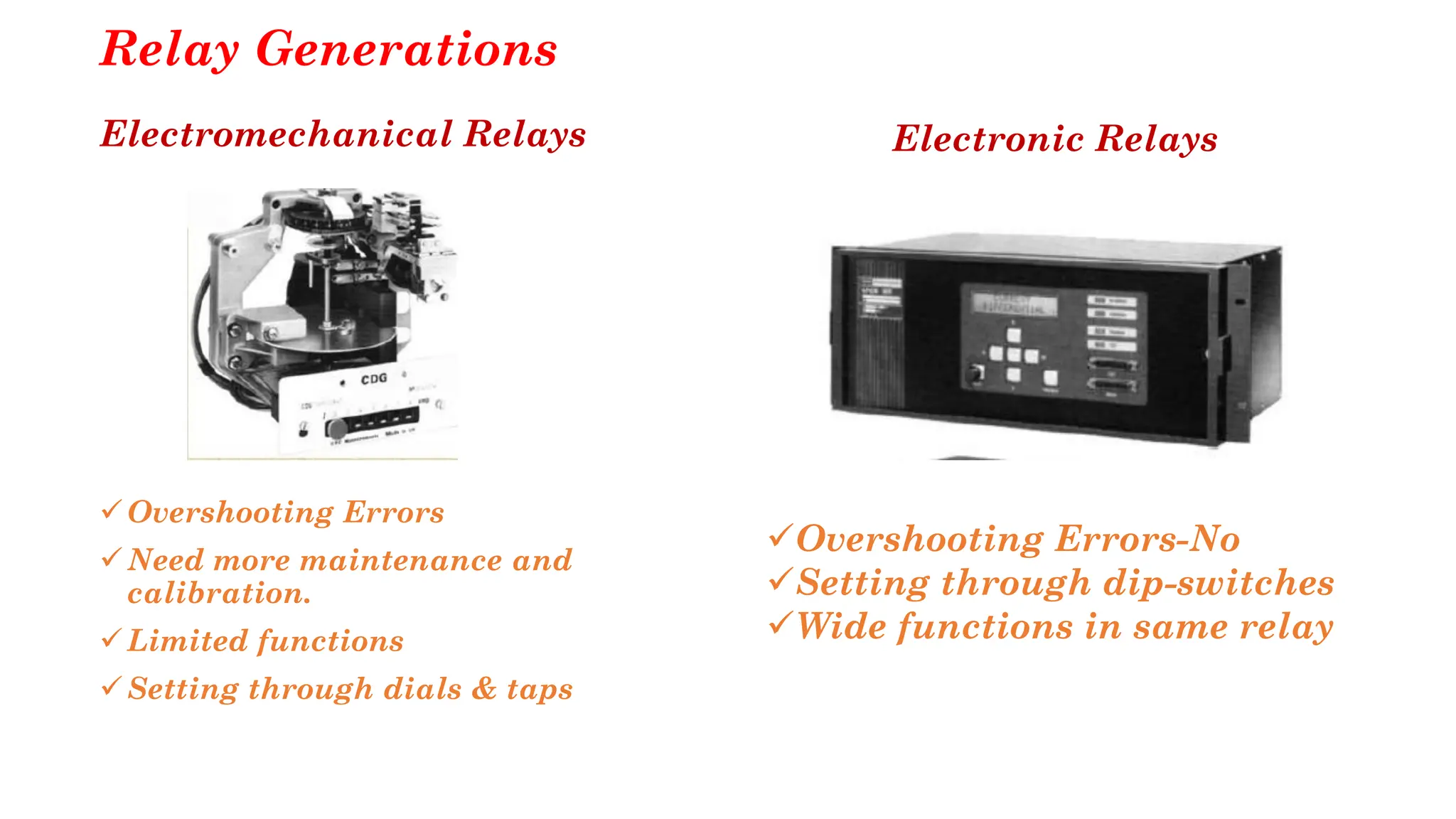
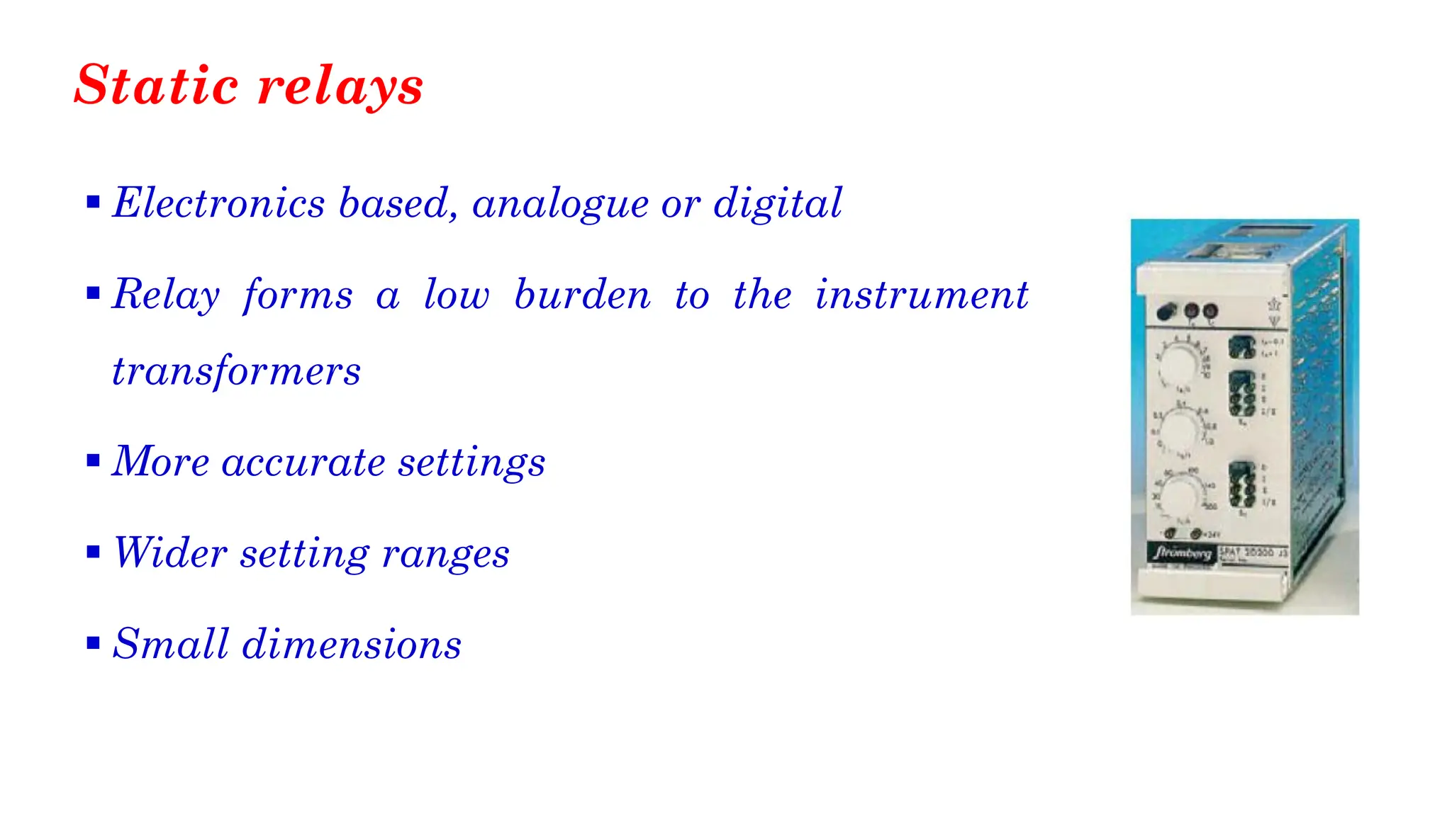
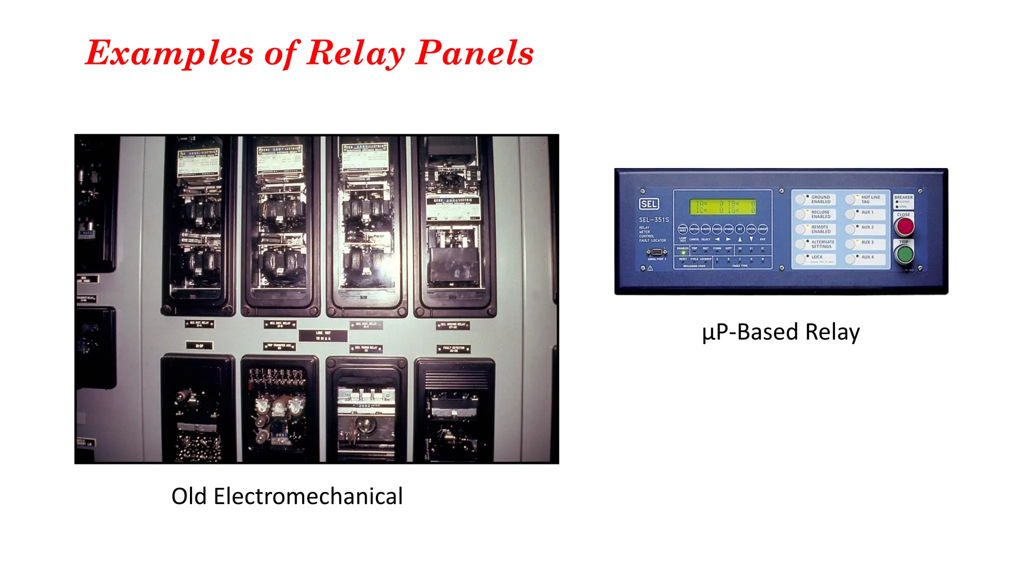
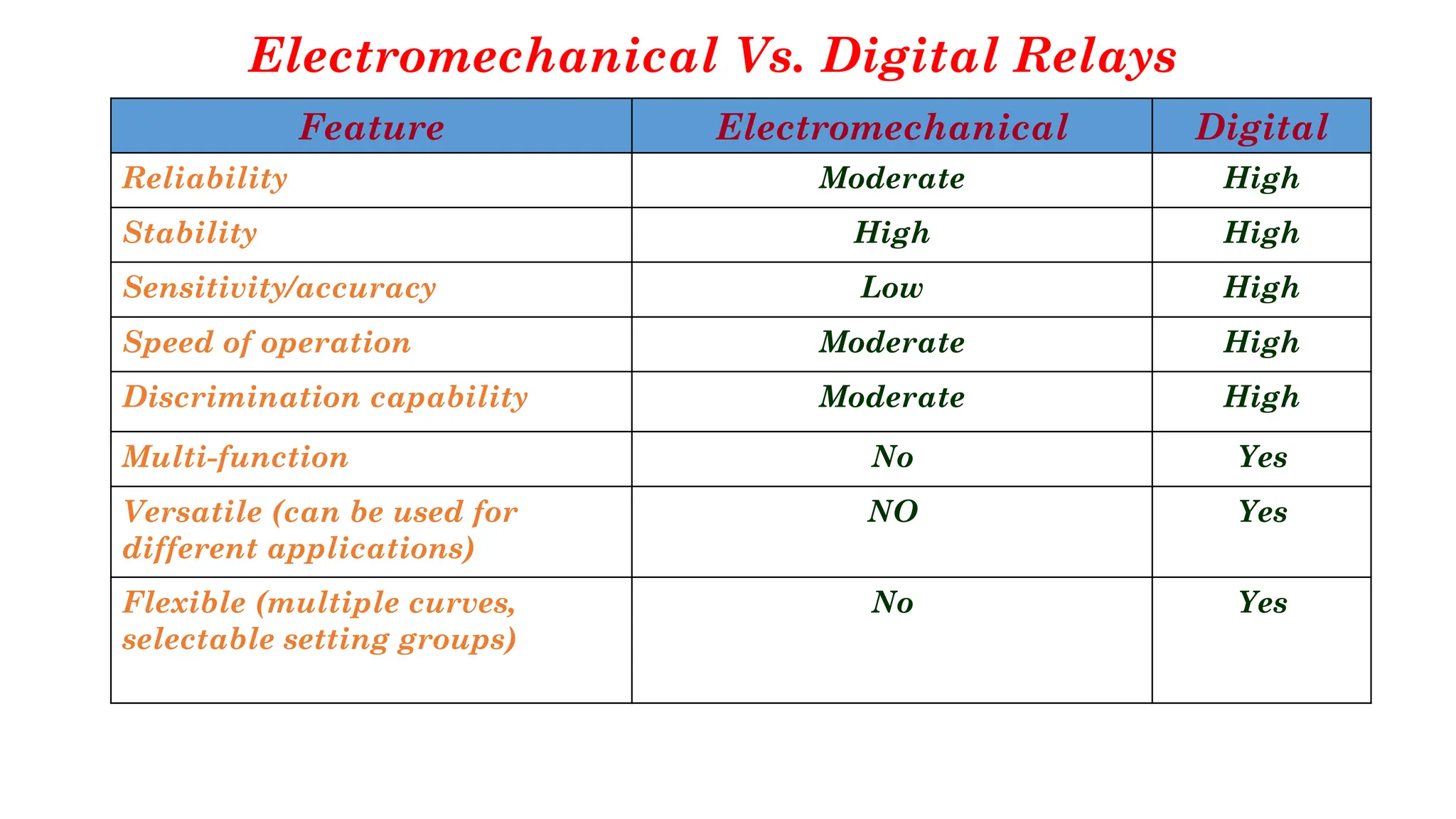
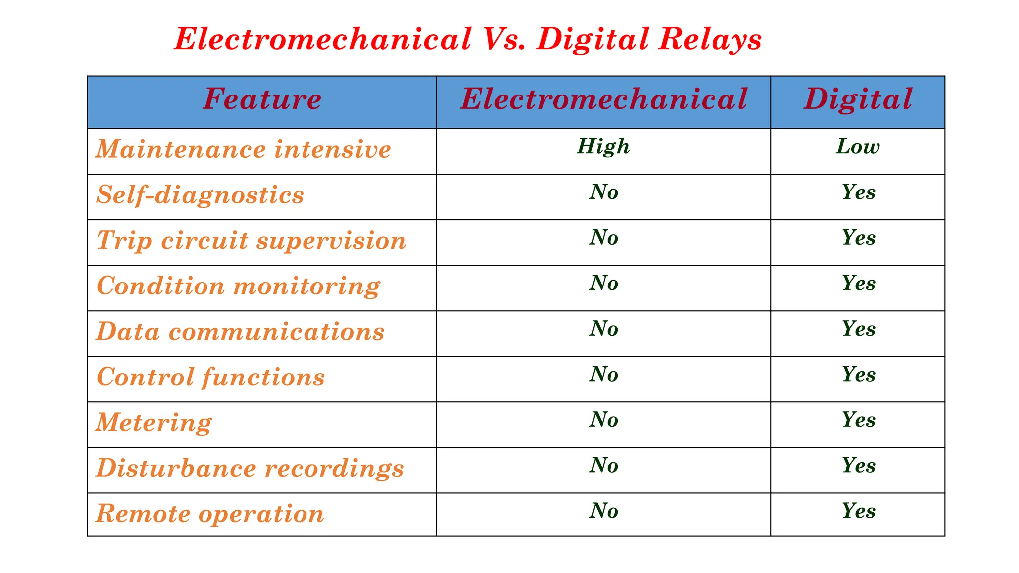
Introduction to Power System
Protection
Attia El-Fergany
Professor of EPS and Protection
Power System Protection
✓Course Code: EPE 426
✓Contents / Couse Specifications
✓Marks (Semester Work 50 / Final written 100)
✓Stuff of Materials:
http://www.aahusseinali.faculty.zu.edu.eg/
Course Aims
▪ The aim of this course is to provide students with the knowledge and skills to
define the function of protective system. The main power system protection
function is to detect and disconnect the faulted element. This prevents further
damage in the faulted element and protects the power system against the fault.
Another important function of protection systems is to provide an indication of
the fault in order to facilitate restoration. Fault location information provided
by digital relays helps line repair crews reduce repair time.
Teaching and Learning Methods
Lecture
Presentations
Discussion
Tutorial
Problem Solving
Group Working
Research and Reporting
Projects
Reading Materials
References
A protection apparatus has three main
functions/duties:
▪ Safeguard the entire system to maintain continuity of supply
▪ Minimize damage and repair costs where it senses fault
▪ Ensure safety of personnel.
Features of good Protection Schemes
•Selectivity: To detect and isolate the faulty item only.
•Stability: To leave all healthy circuits intact to ensure
continuity or supply.
•Sensitivity: To detect even the smallest fault, current or
system abnormalities and operate correctly at its setting
before the fault causes irreparable damage.
•Speed: To operate speedily when it is called upon to do
so, thereby minimizing damage to the surroundings and
ensuring safety to personnel.
Protection Reliability
▪Dependable: It must trip when called upon to do so.
▪Secure: It must not trip when it is not supposed to.
Power System Protection – Qualities
Reliability
Dependability Security
Reliability
▪Dependability - Correct
operation
▪Security - No incorrect
operation
▪Consistency - Always
the same operation
Economical requirements
1. Availability - Minimum time for repair and maintenance,
2. Simplicity - Minimum equipment and circuitry,
3. Flexibility - For an easy adaptation to the power system,
4. Large life-cycle time.
Dependability, Security and Reliabilty
Dependability % =
# of correct trips
# of desired trips
× 100
Security % =
# of correct trips
total # of trips
× 100
Reliability % =
# of correct trips
# of desired trips+incorrect trips
× 100
Purpose of Protective Relays
▪Detect and isolate equipment failures,,
▪Improve system stability,
▪Protect against overloading,
▪Protect against abnormal conditions of Voltage,
frequency, current,
▪Protect public.
Disturbances: Light or Severe
▪ The power system must maintain acceptable operation 24 hours a
day
• Voltage and frequency must stay within certain limits
▪ Small disturbances
• The control system can handle these
• Example: variation in transformer or generator load
▪ Severe disturbances require a protection system
• They can jeopardize the entire power system
• They cannot be overcome by a control system
Why protection is needed?
➢Relays CANNOT prevent
faults
Protection equipment cannot predict or
prevent a fault from happening?
Protection must cover 100% of the protected network
Back-up Protection
Primary Relaying – Zones of Protection
Back-up Protection
Remote Backup Relaying
All Protection Engineers should be able to:
▪ Calculate power system currents and voltages during fault
conditions,
▪ Check that breaking capacity of switchgear is not exceeded,
▪ Determine the quantities which can be used by relays to
distinguish between healthy (i.e. Loaded) and fault conditions,
▪ Appreciate the effect of the method of earthing (grounding) on the
detection of earth faults,
▪ Select the best relay characteristics for fault detection,
▪ Select relay settings for fault detection and discrimination,
▪ Understand principles of relay operation,
▪ Conduct post fault analysis,
▪ Ensure that load and short circuit ratings of plant are not
exceeded.
All Protection Engineers should be able to:
Protection Using Relayed Circuit Breaker
The Total Clearing Time must be less than
the Equipment Damage Time
Sequence of Events During a Fault
tr= relay time tm = mechanism time ta= arcing time
tcb = CB time tc = total clearing time
Simple Protective Relay
Input/Output Scheme of a µA-Based Relay
Factors Influencing Protection System Design
▪ Types of fault and abnormal conditions to be protected against.
▪ Quantities available for measurement.
▪ Types of protection available.
▪ Speed.
▪ Fault position discrimination.
▪ Dependability / Reliability.
▪ Security / Stability.
▪ Overlap of protections
▪ Phase discrimination / Selectivity
▪ Instrument transformers (CTs & VTs)
▪ Auxiliary supplies
▪ Back-up protection
▪ Cost
▪ Duplication of protection
Circuit Breakers
▪Circuit-breakers are mechanical switching
devices able to make, carry and interrupt
currents occurring in the circuit under normal
conditions, and can make, carry for a
specified time and break currents occurring in
the circuit (e.g. short circuit) under specified
abnormal conditions.
Instrument Transformers
Current Transformers
Very High Voltage CT
Medium-Voltage CT
Voltage Transformers
Medium Voltage
High Voltage
Note: Voltage transformers are also
known as potential transformers
Current and Voltage Transformers
▪ These are an essential part of the protection scheme to reduce primary
current and volts to a low level suitable to input to relay.
▪ They must be suitably specified to meet the requirements of the protective
relays.
▪ Correct connection of CTs and VTs to the protection is important. In
particular for directional, distance, phase comparison and differential
protections.
▪ VTs may be electromagnetic or capacitor types.
▪ Busbar VTs : Special consideration needed when used for line protection.
Instrument Transformer Circuits
▪Never open circuit a CT secondary circuit, so :
• Never fuse CT circuits;
• VTs must be fused or protected by MCB.
• Do wire test blocks in circuit (both VT and CT) to allow
commissioning and periodic injection testing of relays.
• Earth CT and VT circuits at one point only;
• Wire gauge > 2.5mm2 recommended for mechanical
strength.
Types of Protection
▪Fuses
• For : LV Systems, Distribution Feeders and
Transformers, VTs, Auxiliary Supplies.
▪Overcurrent and Earthfault
• Widely used in all Power Systems.
• Non-Directional.
• Voltage Dependant.
• Directional.
Types of Protection
▪Differential
• For : Feeders, Busbars, Transformers, Generators, etc.
• High Impedance
• Restricted E/F
• Biased (or low-impedance)
• Pilot Wire
• Digital
Types of Protection
▪Distance
• For : Distribution Feeders and Transmission and Sub-
Transmission Circuits
• Also used as Back-up Protection for Transformers and
Generators
▪Phase Comparison
• For : Transmission Lines
▪Directional Comparison
• For : Transmission Lines
Types of Protection
▪Miscellaneous
• Under and Over Voltage.
• Under and Over Frequency.
• Special Relays for Generators, Transformers, Motors,
etc.
▪Control Relays
• Auto-Reclose, Tap Change Control, etc.
▪ Tripping and Auxiliary Relays.
Relay Generations
Electromechanical Relays
✓Overshooting Errors
✓Need more maintenance and
calibration.
✓Limited functions
✓Setting through dials & taps
Electronic Relays
✓Overshooting Errors-No
✓Setting through dip-switches
✓Wide functions in same relay
Electromechanical relays
▪ 1st generation, primary connected Measurement
▪ 2nd generation, power supplied from the instrument transformers
• Relay forms a high burden to the instrument trafos
• High risk of saturation of CTs, especially when there is a DC component
in the fault current
• A lot of mechanical parts, requires regular maintenance
• Unaccurate and unsensitive settings
Static relays
▪ Electronics based, analogue or digital
▪ Relay forms a low burden to the instrument
transformers
▪ More accurate settings
▪ Wider setting ranges
▪ Small dimensions
Numerical Relays
▪ µP technology provides features as in statical relays
and more…
▪ Many protection functions integrated in one relay
▪ Self supervision of hardware and software Extensive
information handling, due to communication
▪ Integrated protection, measurement, control,
condition monitoring, communication etc, in so called
feeder terminals
Why Digital Relays
✓To improve dependability as well as security,
✓Self checking facility,
✓Immune to variation in parameters of individual
components,
✓Very low burden,
✓More flexibility because of Programmable capability,
✓Simple & Smaller Size,
✓Cheaper,
✓Less Maintenance,
Why Digital Relays
✓Fault record & event logger,
✓Relay data accessed remotely,
✓Fiber optical communication with substation LAN,
✓Adaptive relaying schemes,
✓Permit Historical data storage,
✓Allow GPS (Geographical Positioning System) Time
stamping.
The next generation of protective relays
✓Past – electromechanical
✓Present - static and µP
✓Future - Intelligent?
(ANN, ES based, GA, etc …)
Examples of Relay Panels
Old Electromechanical
µP-Based Relay
Electromechanical Vs. Digital Relays
Feature Electromechanical Digital
Reliability Moderate High
Stability High High
Sensitivity/accuracy Low High
Speed of operation Moderate High
Discrimination capability Moderate High
Multi-function No Yes
Versatile (can be used for
different applications)
NO Yes
Flexible (multiple curves,
selectable setting groups)
No Yes
Electromechanical Vs. Digital Relays
Feature Electromechanical Digital
Maintenance intensive High Low
Self-diagnostics No Yes
Trip circuit supervision No Yes
Condition monitoring No Yes
Data communications No Yes
Control functions No Yes
Metering No Yes
Disturbance recordings No Yes
Remote operation No Yes
Relay symbols and device numbers - Sample
IEC 60617-series IEEE C37.2
50
Abbreviated list of commonly used
relay device function numbers
No. Description
2 Time-delay
21 Distance
25 Synchronism-check
27 Undervoltage
30 Annunciator
32 Directional power
37 Undercurrent or underpower
51
Abbreviated list of commonly used
relay device function numbers
No. Description
38 Bearing
40 Field
46 Reverse-phase
47 Phase-sequence voltage
49 Thermal
50 Instantaneous overcurrent
51 AC time overcurrent
52
Abbreviated list of commonly used
relay device function numbers
No. Description
59 Overvoltage
60 Voltage balance
63 Pressure
64 Ground
67 AC directional overcurrent
68 Blocking
69 Permissive
53
Abbreviated list of commonly used
relay device function numbers
No. Description
74 Alarm
76 DC overcurrent
78 Out-of-step
79 AC reclosing
81 Frequency
85 Carrier or pilot-wire
86 Lock out
E N D
Any Questions,
Please…
54

Lec 1_Introduction to Power System Protection.pdf

  • 1.
    Introduction to PowerSystem Protection Attia El-Fergany Professor of EPS and Protection
  • 2.
    Power System Protection ✓CourseCode: EPE 426 ✓Contents / Couse Specifications ✓Marks (Semester Work 50 / Final written 100) ✓Stuff of Materials: http://www.aahusseinali.faculty.zu.edu.eg/
  • 3.
    Course Aims ▪ Theaim of this course is to provide students with the knowledge and skills to define the function of protective system. The main power system protection function is to detect and disconnect the faulted element. This prevents further damage in the faulted element and protects the power system against the fault. Another important function of protection systems is to provide an indication of the fault in order to facilitate restoration. Fault location information provided by digital relays helps line repair crews reduce repair time.
  • 4.
    Teaching and LearningMethods Lecture Presentations Discussion Tutorial Problem Solving Group Working Research and Reporting Projects Reading Materials
  • 5.
  • 8.
    A protection apparatushas three main functions/duties: ▪ Safeguard the entire system to maintain continuity of supply ▪ Minimize damage and repair costs where it senses fault ▪ Ensure safety of personnel.
  • 9.
    Features of goodProtection Schemes •Selectivity: To detect and isolate the faulty item only. •Stability: To leave all healthy circuits intact to ensure continuity or supply. •Sensitivity: To detect even the smallest fault, current or system abnormalities and operate correctly at its setting before the fault causes irreparable damage. •Speed: To operate speedily when it is called upon to do so, thereby minimizing damage to the surroundings and ensuring safety to personnel.
  • 10.
    Protection Reliability ▪Dependable: Itmust trip when called upon to do so. ▪Secure: It must not trip when it is not supposed to.
  • 11.
    Power System Protection– Qualities Reliability Dependability Security
  • 12.
    Reliability ▪Dependability - Correct operation ▪Security- No incorrect operation ▪Consistency - Always the same operation
  • 13.
    Economical requirements 1. Availability- Minimum time for repair and maintenance, 2. Simplicity - Minimum equipment and circuitry, 3. Flexibility - For an easy adaptation to the power system, 4. Large life-cycle time.
  • 14.
    Dependability, Security andReliabilty Dependability % = # of correct trips # of desired trips × 100 Security % = # of correct trips total # of trips × 100 Reliability % = # of correct trips # of desired trips+incorrect trips × 100
  • 15.
    Purpose of ProtectiveRelays ▪Detect and isolate equipment failures,, ▪Improve system stability, ▪Protect against overloading, ▪Protect against abnormal conditions of Voltage, frequency, current, ▪Protect public.
  • 16.
    Disturbances: Light orSevere ▪ The power system must maintain acceptable operation 24 hours a day • Voltage and frequency must stay within certain limits ▪ Small disturbances • The control system can handle these • Example: variation in transformer or generator load ▪ Severe disturbances require a protection system • They can jeopardize the entire power system • They cannot be overcome by a control system
  • 17.
    Why protection isneeded? ➢Relays CANNOT prevent faults Protection equipment cannot predict or prevent a fault from happening?
  • 18.
    Protection must cover100% of the protected network
  • 19.
    Back-up Protection Primary Relaying– Zones of Protection
  • 20.
  • 21.
    All Protection Engineersshould be able to: ▪ Calculate power system currents and voltages during fault conditions, ▪ Check that breaking capacity of switchgear is not exceeded, ▪ Determine the quantities which can be used by relays to distinguish between healthy (i.e. Loaded) and fault conditions, ▪ Appreciate the effect of the method of earthing (grounding) on the detection of earth faults,
  • 22.
    ▪ Select thebest relay characteristics for fault detection, ▪ Select relay settings for fault detection and discrimination, ▪ Understand principles of relay operation, ▪ Conduct post fault analysis, ▪ Ensure that load and short circuit ratings of plant are not exceeded. All Protection Engineers should be able to:
  • 23.
    Protection Using RelayedCircuit Breaker The Total Clearing Time must be less than the Equipment Damage Time
  • 24.
    Sequence of EventsDuring a Fault tr= relay time tm = mechanism time ta= arcing time tcb = CB time tc = total clearing time
  • 25.
  • 26.
    Input/Output Scheme ofa µA-Based Relay
  • 27.
    Factors Influencing ProtectionSystem Design ▪ Types of fault and abnormal conditions to be protected against. ▪ Quantities available for measurement. ▪ Types of protection available. ▪ Speed. ▪ Fault position discrimination. ▪ Dependability / Reliability. ▪ Security / Stability. ▪ Overlap of protections ▪ Phase discrimination / Selectivity ▪ Instrument transformers (CTs & VTs) ▪ Auxiliary supplies ▪ Back-up protection ▪ Cost ▪ Duplication of protection
  • 28.
    Circuit Breakers ▪Circuit-breakers aremechanical switching devices able to make, carry and interrupt currents occurring in the circuit under normal conditions, and can make, carry for a specified time and break currents occurring in the circuit (e.g. short circuit) under specified abnormal conditions.
  • 29.
  • 30.
    Current Transformers Very HighVoltage CT Medium-Voltage CT
  • 31.
    Voltage Transformers Medium Voltage HighVoltage Note: Voltage transformers are also known as potential transformers
  • 32.
    Current and VoltageTransformers ▪ These are an essential part of the protection scheme to reduce primary current and volts to a low level suitable to input to relay. ▪ They must be suitably specified to meet the requirements of the protective relays. ▪ Correct connection of CTs and VTs to the protection is important. In particular for directional, distance, phase comparison and differential protections. ▪ VTs may be electromagnetic or capacitor types. ▪ Busbar VTs : Special consideration needed when used for line protection.
  • 33.
    Instrument Transformer Circuits ▪Neveropen circuit a CT secondary circuit, so : • Never fuse CT circuits; • VTs must be fused or protected by MCB. • Do wire test blocks in circuit (both VT and CT) to allow commissioning and periodic injection testing of relays. • Earth CT and VT circuits at one point only; • Wire gauge > 2.5mm2 recommended for mechanical strength.
  • 34.
    Types of Protection ▪Fuses •For : LV Systems, Distribution Feeders and Transformers, VTs, Auxiliary Supplies. ▪Overcurrent and Earthfault • Widely used in all Power Systems. • Non-Directional. • Voltage Dependant. • Directional.
  • 35.
    Types of Protection ▪Differential •For : Feeders, Busbars, Transformers, Generators, etc. • High Impedance • Restricted E/F • Biased (or low-impedance) • Pilot Wire • Digital
  • 36.
    Types of Protection ▪Distance •For : Distribution Feeders and Transmission and Sub- Transmission Circuits • Also used as Back-up Protection for Transformers and Generators ▪Phase Comparison • For : Transmission Lines ▪Directional Comparison • For : Transmission Lines
  • 37.
    Types of Protection ▪Miscellaneous •Under and Over Voltage. • Under and Over Frequency. • Special Relays for Generators, Transformers, Motors, etc. ▪Control Relays • Auto-Reclose, Tap Change Control, etc. ▪ Tripping and Auxiliary Relays.
  • 38.
    Relay Generations Electromechanical Relays ✓OvershootingErrors ✓Need more maintenance and calibration. ✓Limited functions ✓Setting through dials & taps Electronic Relays ✓Overshooting Errors-No ✓Setting through dip-switches ✓Wide functions in same relay
  • 39.
    Electromechanical relays ▪ 1stgeneration, primary connected Measurement ▪ 2nd generation, power supplied from the instrument transformers • Relay forms a high burden to the instrument trafos • High risk of saturation of CTs, especially when there is a DC component in the fault current • A lot of mechanical parts, requires regular maintenance • Unaccurate and unsensitive settings
  • 40.
    Static relays ▪ Electronicsbased, analogue or digital ▪ Relay forms a low burden to the instrument transformers ▪ More accurate settings ▪ Wider setting ranges ▪ Small dimensions
  • 41.
    Numerical Relays ▪ µPtechnology provides features as in statical relays and more… ▪ Many protection functions integrated in one relay ▪ Self supervision of hardware and software Extensive information handling, due to communication ▪ Integrated protection, measurement, control, condition monitoring, communication etc, in so called feeder terminals
  • 42.
    Why Digital Relays ✓Toimprove dependability as well as security, ✓Self checking facility, ✓Immune to variation in parameters of individual components, ✓Very low burden, ✓More flexibility because of Programmable capability, ✓Simple & Smaller Size, ✓Cheaper, ✓Less Maintenance,
  • 43.
    Why Digital Relays ✓Faultrecord & event logger, ✓Relay data accessed remotely, ✓Fiber optical communication with substation LAN, ✓Adaptive relaying schemes, ✓Permit Historical data storage, ✓Allow GPS (Geographical Positioning System) Time stamping.
  • 44.
    The next generationof protective relays ✓Past – electromechanical ✓Present - static and µP ✓Future - Intelligent? (ANN, ES based, GA, etc …)
  • 45.
    Examples of RelayPanels Old Electromechanical µP-Based Relay
  • 46.
    Electromechanical Vs. DigitalRelays Feature Electromechanical Digital Reliability Moderate High Stability High High Sensitivity/accuracy Low High Speed of operation Moderate High Discrimination capability Moderate High Multi-function No Yes Versatile (can be used for different applications) NO Yes Flexible (multiple curves, selectable setting groups) No Yes
  • 47.
    Electromechanical Vs. DigitalRelays Feature Electromechanical Digital Maintenance intensive High Low Self-diagnostics No Yes Trip circuit supervision No Yes Condition monitoring No Yes Data communications No Yes Control functions No Yes Metering No Yes Disturbance recordings No Yes Remote operation No Yes
  • 48.
    Relay symbols anddevice numbers - Sample IEC 60617-series IEEE C37.2
  • 49.
    50 Abbreviated list ofcommonly used relay device function numbers No. Description 2 Time-delay 21 Distance 25 Synchronism-check 27 Undervoltage 30 Annunciator 32 Directional power 37 Undercurrent or underpower
  • 50.
    51 Abbreviated list ofcommonly used relay device function numbers No. Description 38 Bearing 40 Field 46 Reverse-phase 47 Phase-sequence voltage 49 Thermal 50 Instantaneous overcurrent 51 AC time overcurrent
  • 51.
    52 Abbreviated list ofcommonly used relay device function numbers No. Description 59 Overvoltage 60 Voltage balance 63 Pressure 64 Ground 67 AC directional overcurrent 68 Blocking 69 Permissive
  • 52.
    53 Abbreviated list ofcommonly used relay device function numbers No. Description 74 Alarm 76 DC overcurrent 78 Out-of-step 79 AC reclosing 81 Frequency 85 Carrier or pilot-wire 86 Lock out
  • 53.
    E N D AnyQuestions, Please… 54