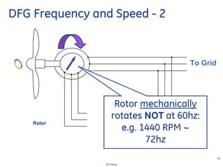
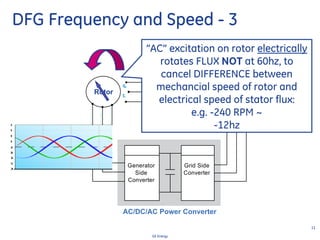
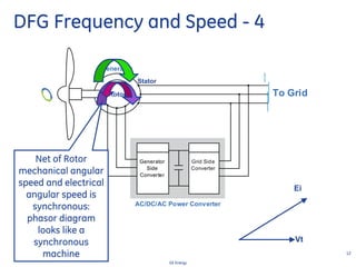
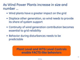
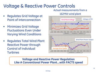
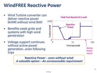
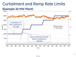
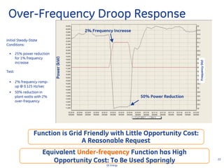
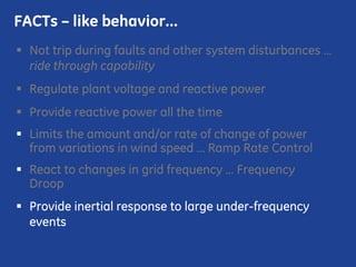
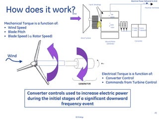
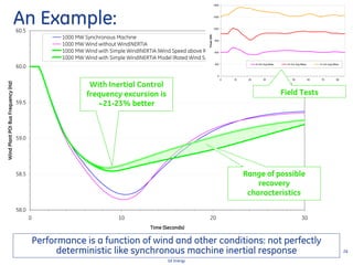
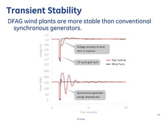
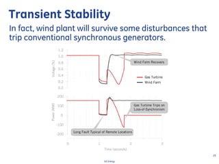
GE Energy
Facts On Grid Friendly Wind
Plants
Nicholas W. Miller
Paul E. Marken
July, 2010
IEEE GPM Minneapolis
2
GE Energy
Wind Generators are Different
Wind Turbines Need to have some degree of
speed variability due to the need to:
1. Control mechanical loads
2. Maximize energy capture (efficiency)
3
GE Energy
Structure of wind turbine generator
systems - Overall structure
Rotor
NacelleHub
Tower
Tower base
4
GE Energy
Structure of wind turbine generator
systems - Nacelle
Nose
cone
Rotor shaft
Pitch drive
Oil cooler
Hub
Main bearing
Obstruction
lights
Control
Cooler
Casing
Generator
Ground frame
Noise decoupling Yaw drives
Coupling
Gearbox
5
GE Energy
Aerodynamic Fundamentals
Rotor power: P = 1/2 cp ρAvw
3
cp - rotor power coefficient
ρ - air density
A - rotor swept area
Ideal cp = 0.593 (Betz factor)
Tip speed ratio: λ = vt / vw
cp = f(λ)
max for 3 blade rotor: cp = 0.47 at λ = 7
max for 2 blade rotor: cp = 0.45 at λ = 10
• to operate at peak cp requires variable rotor speed
• 2 blade machine will spin 30% faster, slightly lower cp
• diminishing returns for more than 3 blades
“Windturbines: Fundamentals, Technologies, Application and
Economics”, Erich Hau, ISBN: 3540570640; (April 30, 2000)
Wind Speed
Tip Speed Ratio λ
PowerCoefficeintCp
λ ∼ 7
6
GE Energy
Wind Turbine Generator
Electrical Conversion Technologies
• Type 1 – Squirrel-cage induction generator
• Type 2 – Wound rotor induction generator with variable rotor resistance
• Type 3 – Doubly-fed asynchronous generator
• Type 4 – Full converter interface
generator
Plant
Feeders
PF control
capacitors
generator
Slip power
as heat loss
Plant
Feeders
PF control
capacitors
ac
to
dc
generator
partial power
Plant
Feeders
ac
to
dc
dc
to
ac
generator
full power
Plant
Feeders
ac
to
dc
dc
to
ac
7
GE Energy
What Really is a Doubly-Fed
Generator?
• Physically – the machine resembles an induction
generator
• Conceptually – it is like a variable speed,
“synchronous” generator with bus-fed excitation
• Functionally – it tends to operate more like a
current-regulated electronic converter
It is not just a type of “induction generator”;
operationally, there is little in common with an
induction generator
8
GE Energy
Doubly-Fed Asynchronous Generators
• Machine is wound-rotor induction-type generator with 3-phase rotor winding
• AC “excitation” supplied to rotor
• Excitation supplied by a line-fed pulse-width modulated (PWM) converter
Wind Turbine
Generator
Side
Converter
Grid Side
Converter
Generator
AC/DC/AC Power Converter
To GridRotor
Stator
Generator
Side
Converter
Generator
Side
Converter
Grid Side
Converter
Generator
AC/DC/AC Power Converter
To GridRotor
Stator
9
GE Energy
DFG Frequency and Speed - 1
To Grid
Stator
60 Hz
Stator MMF rotates in
airgap at 60hz:
e.g. 1200 RPM
10
GE Energy
DFG Frequency and Speed - 2
To Grid
Rotor
Rotor mechanically
rotates NOT at 60hz:
e.g. 1440 RPM ~
72hz
11
GE Energy
DFG Frequency and Speed - 3
Generator
Side
Converter
Grid Side
Converter
AC/DC/AC Power Converter
To GridRotor
“AC” excitation on rotor electrically
rotates FLUX NOT at 60hz, to
cancel DIFFERENCE between
mechancial speed of rotor and
electrical speed of stator flux:
e.g. -240 RPM ~
-12hz
12
GE Energy
Generator
Side
Converter
Grid Side
Converter
Generator
AC/DC/AC Power Converter
To GridRotor
Stator
Generator
Side
Converter
Generator
Side
Converter
Grid Side
Converter
Generator
AC/DC/AC Power Converter
To GridRotor
Stator
DFG Frequency and Speed - 4
Net of Rotor
mechanical angular
speed and electrical
angular speed is
synchronous:
phasor diagram
looks like a
synchronous
machine
Ei
Vt
13
GE Energy
• Wind plants have a greater impact on the grid
• Displace other generation, so wind needs to provide
its share of system support
• Continuity of wind generation contribution becomes
essential to grid reliability
• Behavior during disturbances needs to be
predictable
As Wind Power Plants increase in size and
number …
Plant Level and WTG Level Controls
enable FACTS-like behaviors
Not trip during faults and other system disturbances …
FACTs – like behavior…
15
GE Energy
3-phase 18.5% retained voltage, 700ms fault:
P, Q (Mw,Mvar)
Reactive Power well
behaved: like a
STATCOM - supports
grid during voltage
depression
Field Test Results (2.5 unit)
Not trip during faults and other system disturbances …
ride through capability
Regulate plant voltage & reactive power
Provide reactive power all the time
FACTs – like behavior…
17
GE Energy
WTG Reactive Power Capability
• Full leading and lagging range over full power range
• Faster reactive response than synch. generator
• Capability of reactive compensation with no wind
• Behavior like a FACTS devices
18
GE Energy
Voltage at POI
Wind Plant Power Output
Voltage & Reactive Power Controls
Actual measurements from a
162MW wind plant
Wind Plant Voltage
• Regulates Grid Voltage at
Point of Interconnection
• Minimizes Grid Voltage
Fluctuations Even Under
Varying Wind Conditions
• Regulates Total Wind Plant
Reactive Power through
Control of Individual
Turbines
Average Wind Speed
Voltage and Reactive Power Regulation
Like A Conventional Power Plant…with FACTS speed
19
GE Energy
TurbinekVAR
75
Time (seconds)
1500
0
1500
TurbinekVAR
75
Time (seconds)
1500
0
1500
WindFREE Reactive Power
• Wind Turbine converter can
deliver reactive power
(kVAR) without wind (kW)
• Benefits weak grids and
systems with high wind
penetration
• Voltage support continues
without active power
generation…even following
trips
Active
Power
(zero)
Reactive
Power
Field Test Results (2.5 unit)
Reactive Power - even without wind:
A valuable option – An unreasonable requirement
Not trip during faults and other system disturbances …
ride through capability
Regulate plant voltage and reactive power
Provide reactive power all the time
Limits the amount and/or rate of change of power
from variations in wind speed … Ramp Rate Control
React to changes in grid frequency … Frequency Droop
FACTs – like behavior…
21
GE Energy
0
5000
10000
15000
20000
25000
30000
35000
4:30:00
AM
4:38:00
AM
4:46:00
AM
4:54:00
AM
5:02:00
AM
5:10:00
AM
5:18:00
AM
5:26:00
AM
5:34:00
AM
5:42:00
AM
5:50:00
AM
5:58:00
AM
6:06:00
AM
6:14:00
AM
6:22:00
AM
6:30:00
AM
Time
PowerkW
0
5
10
15
20
Actual power
Wind speed
Curtailment and Ramp Rate Limits
(Example 30 MW Plant)
Ramp rate limit enforced
when curtailment is
released
Curtailed to 10
MW: regulation is
very tight
22
GE Energy
Over-Frequency Droop Response
2% Frequency Increase
50% Power Reduction
Power(kW)
Frequency(Hz)
Function is Grid Friendly with Little Opportunity Cost:
A Reasonable Request
Initial Steady-State
Conditions:
• 25% power reduction
for 1% frequency
increase
Test:
• 2% frequency ramp-
up @ 0.125 Hz/sec
• 50% reduction in
plant watts with 2%
over-frequency
Equivalent Under-frequency Function has High
Opportunity Cost: To Be Used Sparingly
Not trip during faults and other system disturbances …
ride through capability
Regulate plant voltage and reactive power
Provide reactive power all the time
Limits the amount and/or rate of change of power
from variations in wind speed … Ramp Rate Control
React to changes in grid frequency … Frequency
Droop
Provide inertial response to large under-frequency
events
FACTs – like behavior…
24
GE Energy
Why Inertial Response: System Needs
• Increasing Dependence on Wind Power
– Large Grids with Significant Penetration of Wind Power
• Modern variable speed wind turbine-generators do not
contribute to system inertia
• System inertia declines as wind generation displaces
synchronous generators (which are de-committed)
• Result is deeper frequency excursions for system
disturbances
• Increased risk of
– Under-frequency load shedding (UFLS)
– Cascading outages
Inertial response enabled by power electronics
enables CONTROLLED performance
(not just Park’s equations!)
25
GE Energy
How does it work?
Wind
Electrical Torque is a function of:
• Converter Control
• Commands from Turbine Control
Mechanical Torque is a function of:
• Wind Speed
• Blade Pitch
• Blade Speed ( α Rotor Speed)
Converter controls used to increase electric power
during the initial stages of a significant downward
frequency event
Wind Turbine
f
rotor
P
rotor
f
net
P
stator
3 φ AC Windings
Converter
P rotor
F rotor
P conv
F network
Electrical Power Delivered to Grid
Wound-Rotor
Generator
Machine Terminals
Wind
26
GE Energy
58.0
58.5
59.0
59.5
60.0
60.5
0 10 20 30
Time (Seconds)
WindPlantPOIBusFrequency(Hz)
1000 MW Synchronous Machine
1000 MW Wind without WindINERTIA
1000 MW Wind with Simple WindINERTIA (Wind Speed above Rated)
1000 MW Wind with Simple WindINERTIA Model (Rated Wind Speed)
With Inertial Control
frequency excursion is
~21-23% better
An Example:
Range of possible
recovery
characteristics
Performance is a function of wind and other conditions: not perfectly
deterministic like synchronous machine inertial response
0
300
600
900
1200
1500
1800
0 10 20 30 40 50 60 70 80
Time (Seconds)
Power(kW)
8 m/s Avg Meas 10 m/s Avg Meas 14 m/s Avg Meas
Field Tests
Transient Stability
Combination of Controls and Power Electronics
of Double Fed Machines radically changes
transient stability behavior:
FACTS-like synchronization…
28
GE Energy
Transient Stability
DFAG wind plants are more stable than conventional
synchronous generators.
29
GE Energy
Transient Stability
In fact, wind plant will survive some disturbances that
trip conventional synchronous generators.
GE Energy
Thanks

Facts on Grid Friendly Wind Plants

  • 1.
    GE Energy Facts OnGrid Friendly Wind Plants Nicholas W. Miller Paul E. Marken July, 2010 IEEE GPM Minneapolis
  • 2.
    2 GE Energy Wind Generatorsare Different Wind Turbines Need to have some degree of speed variability due to the need to: 1. Control mechanical loads 2. Maximize energy capture (efficiency)
  • 3.
    3 GE Energy Structure ofwind turbine generator systems - Overall structure Rotor NacelleHub Tower Tower base
  • 4.
    4 GE Energy Structure ofwind turbine generator systems - Nacelle Nose cone Rotor shaft Pitch drive Oil cooler Hub Main bearing Obstruction lights Control Cooler Casing Generator Ground frame Noise decoupling Yaw drives Coupling Gearbox
  • 5.
    5 GE Energy Aerodynamic Fundamentals Rotorpower: P = 1/2 cp ρAvw 3 cp - rotor power coefficient ρ - air density A - rotor swept area Ideal cp = 0.593 (Betz factor) Tip speed ratio: λ = vt / vw cp = f(λ) max for 3 blade rotor: cp = 0.47 at λ = 7 max for 2 blade rotor: cp = 0.45 at λ = 10 • to operate at peak cp requires variable rotor speed • 2 blade machine will spin 30% faster, slightly lower cp • diminishing returns for more than 3 blades “Windturbines: Fundamentals, Technologies, Application and Economics”, Erich Hau, ISBN: 3540570640; (April 30, 2000) Wind Speed Tip Speed Ratio λ PowerCoefficeintCp λ ∼ 7
  • 6.
    6 GE Energy Wind TurbineGenerator Electrical Conversion Technologies • Type 1 – Squirrel-cage induction generator • Type 2 – Wound rotor induction generator with variable rotor resistance • Type 3 – Doubly-fed asynchronous generator • Type 4 – Full converter interface generator Plant Feeders PF control capacitors generator Slip power as heat loss Plant Feeders PF control capacitors ac to dc generator partial power Plant Feeders ac to dc dc to ac generator full power Plant Feeders ac to dc dc to ac
  • 7.
    7 GE Energy What Reallyis a Doubly-Fed Generator? • Physically – the machine resembles an induction generator • Conceptually – it is like a variable speed, “synchronous” generator with bus-fed excitation • Functionally – it tends to operate more like a current-regulated electronic converter It is not just a type of “induction generator”; operationally, there is little in common with an induction generator
  • 8.
    8 GE Energy Doubly-Fed AsynchronousGenerators • Machine is wound-rotor induction-type generator with 3-phase rotor winding • AC “excitation” supplied to rotor • Excitation supplied by a line-fed pulse-width modulated (PWM) converter Wind Turbine Generator Side Converter Grid Side Converter Generator AC/DC/AC Power Converter To GridRotor Stator Generator Side Converter Generator Side Converter Grid Side Converter Generator AC/DC/AC Power Converter To GridRotor Stator
  • 9.
    9 GE Energy DFG Frequencyand Speed - 1 To Grid Stator 60 Hz Stator MMF rotates in airgap at 60hz: e.g. 1200 RPM
  • 10.
    10 GE Energy DFG Frequencyand Speed - 2 To Grid Rotor Rotor mechanically rotates NOT at 60hz: e.g. 1440 RPM ~ 72hz
  • 11.
    11 GE Energy DFG Frequencyand Speed - 3 Generator Side Converter Grid Side Converter AC/DC/AC Power Converter To GridRotor “AC” excitation on rotor electrically rotates FLUX NOT at 60hz, to cancel DIFFERENCE between mechancial speed of rotor and electrical speed of stator flux: e.g. -240 RPM ~ -12hz
  • 12.
    12 GE Energy Generator Side Converter Grid Side Converter Generator AC/DC/ACPower Converter To GridRotor Stator Generator Side Converter Generator Side Converter Grid Side Converter Generator AC/DC/AC Power Converter To GridRotor Stator DFG Frequency and Speed - 4 Net of Rotor mechanical angular speed and electrical angular speed is synchronous: phasor diagram looks like a synchronous machine Ei Vt
  • 13.
    13 GE Energy • Windplants have a greater impact on the grid • Displace other generation, so wind needs to provide its share of system support • Continuity of wind generation contribution becomes essential to grid reliability • Behavior during disturbances needs to be predictable As Wind Power Plants increase in size and number … Plant Level and WTG Level Controls enable FACTS-like behaviors
  • 14.
    Not trip duringfaults and other system disturbances … FACTs – like behavior…
  • 15.
    15 GE Energy 3-phase 18.5%retained voltage, 700ms fault: P, Q (Mw,Mvar) Reactive Power well behaved: like a STATCOM - supports grid during voltage depression Field Test Results (2.5 unit)
  • 16.
    Not trip duringfaults and other system disturbances … ride through capability Regulate plant voltage & reactive power Provide reactive power all the time FACTs – like behavior…
  • 17.
    17 GE Energy WTG ReactivePower Capability • Full leading and lagging range over full power range • Faster reactive response than synch. generator • Capability of reactive compensation with no wind • Behavior like a FACTS devices
  • 18.
    18 GE Energy Voltage atPOI Wind Plant Power Output Voltage & Reactive Power Controls Actual measurements from a 162MW wind plant Wind Plant Voltage • Regulates Grid Voltage at Point of Interconnection • Minimizes Grid Voltage Fluctuations Even Under Varying Wind Conditions • Regulates Total Wind Plant Reactive Power through Control of Individual Turbines Average Wind Speed Voltage and Reactive Power Regulation Like A Conventional Power Plant…with FACTS speed
  • 19.
    19 GE Energy TurbinekVAR 75 Time (seconds) 1500 0 1500 TurbinekVAR 75 Time(seconds) 1500 0 1500 WindFREE Reactive Power • Wind Turbine converter can deliver reactive power (kVAR) without wind (kW) • Benefits weak grids and systems with high wind penetration • Voltage support continues without active power generation…even following trips Active Power (zero) Reactive Power Field Test Results (2.5 unit) Reactive Power - even without wind: A valuable option – An unreasonable requirement
  • 20.
    Not trip duringfaults and other system disturbances … ride through capability Regulate plant voltage and reactive power Provide reactive power all the time Limits the amount and/or rate of change of power from variations in wind speed … Ramp Rate Control React to changes in grid frequency … Frequency Droop FACTs – like behavior…
  • 21.
  • 22.
    22 GE Energy Over-Frequency DroopResponse 2% Frequency Increase 50% Power Reduction Power(kW) Frequency(Hz) Function is Grid Friendly with Little Opportunity Cost: A Reasonable Request Initial Steady-State Conditions: • 25% power reduction for 1% frequency increase Test: • 2% frequency ramp- up @ 0.125 Hz/sec • 50% reduction in plant watts with 2% over-frequency Equivalent Under-frequency Function has High Opportunity Cost: To Be Used Sparingly
  • 23.
    Not trip duringfaults and other system disturbances … ride through capability Regulate plant voltage and reactive power Provide reactive power all the time Limits the amount and/or rate of change of power from variations in wind speed … Ramp Rate Control React to changes in grid frequency … Frequency Droop Provide inertial response to large under-frequency events FACTs – like behavior…
  • 24.
    24 GE Energy Why InertialResponse: System Needs • Increasing Dependence on Wind Power – Large Grids with Significant Penetration of Wind Power • Modern variable speed wind turbine-generators do not contribute to system inertia • System inertia declines as wind generation displaces synchronous generators (which are de-committed) • Result is deeper frequency excursions for system disturbances • Increased risk of – Under-frequency load shedding (UFLS) – Cascading outages Inertial response enabled by power electronics enables CONTROLLED performance (not just Park’s equations!)
  • 25.
    25 GE Energy How doesit work? Wind Electrical Torque is a function of: • Converter Control • Commands from Turbine Control Mechanical Torque is a function of: • Wind Speed • Blade Pitch • Blade Speed ( α Rotor Speed) Converter controls used to increase electric power during the initial stages of a significant downward frequency event Wind Turbine f rotor P rotor f net P stator 3 φ AC Windings Converter P rotor F rotor P conv F network Electrical Power Delivered to Grid Wound-Rotor Generator Machine Terminals Wind
  • 26.
    26 GE Energy 58.0 58.5 59.0 59.5 60.0 60.5 0 1020 30 Time (Seconds) WindPlantPOIBusFrequency(Hz) 1000 MW Synchronous Machine 1000 MW Wind without WindINERTIA 1000 MW Wind with Simple WindINERTIA (Wind Speed above Rated) 1000 MW Wind with Simple WindINERTIA Model (Rated Wind Speed) With Inertial Control frequency excursion is ~21-23% better An Example: Range of possible recovery characteristics Performance is a function of wind and other conditions: not perfectly deterministic like synchronous machine inertial response 0 300 600 900 1200 1500 1800 0 10 20 30 40 50 60 70 80 Time (Seconds) Power(kW) 8 m/s Avg Meas 10 m/s Avg Meas 14 m/s Avg Meas Field Tests
  • 27.
    Transient Stability Combination ofControls and Power Electronics of Double Fed Machines radically changes transient stability behavior: FACTS-like synchronization…
  • 28.
    28 GE Energy Transient Stability DFAGwind plants are more stable than conventional synchronous generators.
  • 29.
    29 GE Energy Transient Stability Infact, wind plant will survive some disturbances that trip conventional synchronous generators.
  • 30.