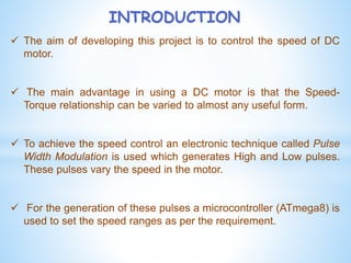
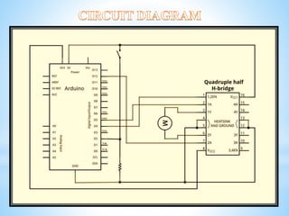
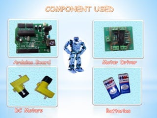
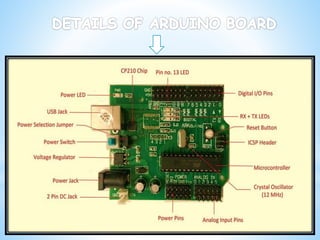
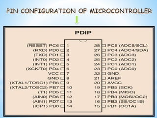
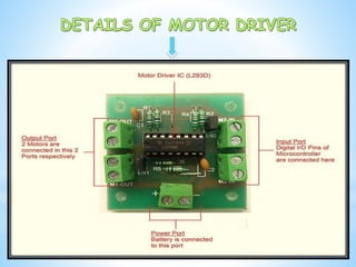
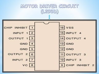
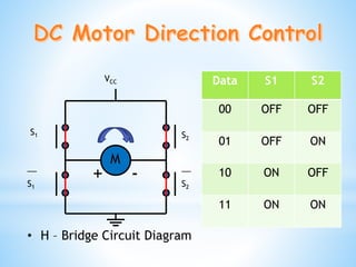
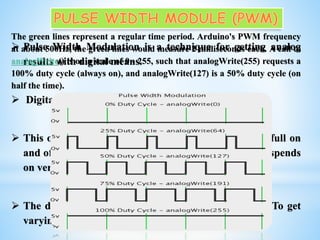
Speed Control ofDC MotorUsingMicrocontroller
Oral Presentation
on
Prepared By-
1. Snehasis Bhar (25301613072)
2. Soumya De (25301613076)
3. Sudip Mondal (25301613087)
Sir J. C. Bose School of Engineering
(Supreme knowledge Foundation group of Institutions)
Mankundu ,Hooghly
INTRODUCTION
 The aim of developing this project is to control the speed of DC
motor.
 The main advantage in using a DC motor is that the Speed-
Torque relationship can be varied to almost any useful form.
 To achieve the speed control an electronic technique called Pulse
Width Modulation is used which generates High and Low pulses.
These pulses vary the speed in the motor.
 For the generation of these pulses a microcontroller (ATmega8) is
used to set the speed ranges as per the requirement.
 The electric and electromechanical methods are less
adaptive so electronic techniques are used for speed
control.
 One such technique is Pulse Width Modulation.
 We can easily apply this technique in Microcontroller
using Aurdino.
 It is easy to compile program with this language.
• H – Bridge Circuit Diagram
S1
__
S1
S2
__
S2
M
+
VCC Data S1 S2
00 OFF OFF
01 OFF ON
10 ON OFF
11 ON ON
-
 Pulse Width Modulation is a technique for getting analog
results with digital means.
 Digital control is used to create a square wave.
 This on-off pattern can simulate voltages in between full on
and off by changing the portion of the time the signal spends
on versus the time that the signal spends off.
 The duration of "on time" is called the pulse width. To get
varying analog values, you change that pulse width.
The green lines represent a regular time period. Arduino's PWM frequency
at about 500Hz, the green lines would measure 2 milliseconds each. A call to
analogWrite() is on a scale of 0 - 255, such that analogWrite(255) requests a
100% duty cycle (always on), and analogWrite(127) is a 50% duty cycle (on
half the time).
 Microcontroller needs software like compiler to
insert logics as inputs.
 It cannot interface high power devices directly.
 It is susceptible to EMI (Electromagnetic
Interference), sometimes even produces audible
noises.
 Speed control is little bit slow due to delay of clock
pulse.
We wish to express our sincere gratitude to Ms.
Srima Nandi, HOD of HU-Department for
giving us such opportunity to do a project. We
sincerely thank Mr. Vishwanath Gupta, Asst.
Prof. of EE-Department for guidance and
encouragement in carrying out this project
work.
Speed Control of DC Motor using Microcontroller

Speed Control of DC Motor using Microcontroller

  • 1.
    Speed Control ofDCMotorUsingMicrocontroller Oral Presentation on Prepared By- 1. Snehasis Bhar (25301613072) 2. Soumya De (25301613076) 3. Sudip Mondal (25301613087) Sir J. C. Bose School of Engineering (Supreme knowledge Foundation group of Institutions) Mankundu ,Hooghly
  • 2.
    INTRODUCTION  The aimof developing this project is to control the speed of DC motor.  The main advantage in using a DC motor is that the Speed- Torque relationship can be varied to almost any useful form.  To achieve the speed control an electronic technique called Pulse Width Modulation is used which generates High and Low pulses. These pulses vary the speed in the motor.  For the generation of these pulses a microcontroller (ATmega8) is used to set the speed ranges as per the requirement.
  • 4.
     The electricand electromechanical methods are less adaptive so electronic techniques are used for speed control.  One such technique is Pulse Width Modulation.  We can easily apply this technique in Microcontroller using Aurdino.  It is easy to compile program with this language.
  • 10.
    • H –Bridge Circuit Diagram S1 __ S1 S2 __ S2 M + VCC Data S1 S2 00 OFF OFF 01 OFF ON 10 ON OFF 11 ON ON -
  • 11.
     Pulse WidthModulation is a technique for getting analog results with digital means.  Digital control is used to create a square wave.  This on-off pattern can simulate voltages in between full on and off by changing the portion of the time the signal spends on versus the time that the signal spends off.  The duration of "on time" is called the pulse width. To get varying analog values, you change that pulse width. The green lines represent a regular time period. Arduino's PWM frequency at about 500Hz, the green lines would measure 2 milliseconds each. A call to analogWrite() is on a scale of 0 - 255, such that analogWrite(255) requests a 100% duty cycle (always on), and analogWrite(127) is a 50% duty cycle (on half the time).
  • 14.
     Microcontroller needssoftware like compiler to insert logics as inputs.  It cannot interface high power devices directly.  It is susceptible to EMI (Electromagnetic Interference), sometimes even produces audible noises.  Speed control is little bit slow due to delay of clock pulse.
  • 15.
    We wish toexpress our sincere gratitude to Ms. Srima Nandi, HOD of HU-Department for giving us such opportunity to do a project. We sincerely thank Mr. Vishwanath Gupta, Asst. Prof. of EE-Department for guidance and encouragement in carrying out this project work.