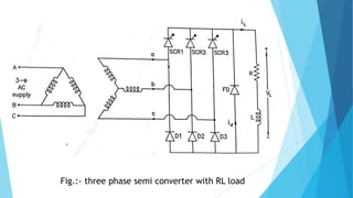
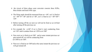
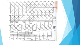
Three phase semi converter
Power electronics -I
PRESENTED BY:-
Rami nirav (161310109048)
Arpit raval (161310109050)
Sem.:-5
Electrical engineering
Fig.:- three phase semi converter with RL load
 the circuit of three phase semi converter consists three SCRs,
three diodes and load of RL type.
 The firing angle should be measured from ωt = 60°, scr1 is fired at
ωt = 60°+0°= 60° and for α= 60°, scr1 is fired at ωt = 60°+60°=
120°.
 Before turning off the scr next scr will not be fired so scr id fired
after turning off the previous scr.
 For example for α=60° if scr is fired it start conducting from
ωt=120° and it conduct from ωt=120°to ωt=240°
 Now next scr is fired at ωt=240° and at same instant previous scr
gets turned off. scr will be conducting from
ωt=240°to ωt=360°.
 Next scr is fired at ωt=360°and at the same instant the previous scr
will get turned off.
 Scr3 is already conducting through D2. scr1 conduct
for 120° and it fired at ωt=60°
 The output voltage vab and vac are obtained when
scr1 is conducting. Similarly vbc and vba are obtained
when scr2 is conducting. Again scr2 conducts for
120°and it is fired at ωt=180°.
 At ωt=300°, when scr3 is fired, voltage vca and vcb
are obtained. Scr3 conduct for 120° from ωt=300°to
ωt=420° the above cycle repeat with scr1.
 The output voltage and current waveforms for α=60°
 scr1 is fired at ωt=120° and scr3 is already conducting through
d2.scr1 and d3 conduct simultaneously for 120° and voltahe vac is
obtained. Scr2 is fired at ωt=240° and it conducts through diode
d1.
 In this case voltage vba is obtained. Similarly the scr3 conducts
and vcb is obtained. here it should be noted that freewheeling
diode does not come into play for α≤60° and voltage vab ,vbc ,vca
do not appear in the output voltage waveform for α=60°.
 The phase voltage are ;
van = vm sinωt
vbn = vm sin(ωt-2∏/3)
vcn = vm sin(ωt+2∏/3)
 And corresponding line to line voltage are
vac = van – vcn = √3vm sin(ωt-∏/6)
vcb = vcn – vbn = √3vm sin(ωt+∏/6)
vab = van – vbn = √3vm sin(ωt+∏/6)
For α≤ 60° ( continues output
voltage);the average voltage is given by
Three phase semi converter

Three phase semi converter

  • 1.
    Three phase semiconverter Power electronics -I PRESENTED BY:- Rami nirav (161310109048) Arpit raval (161310109050) Sem.:-5 Electrical engineering
  • 2.
    Fig.:- three phasesemi converter with RL load
  • 3.
     the circuitof three phase semi converter consists three SCRs, three diodes and load of RL type.  The firing angle should be measured from ωt = 60°, scr1 is fired at ωt = 60°+0°= 60° and for α= 60°, scr1 is fired at ωt = 60°+60°= 120°.  Before turning off the scr next scr will not be fired so scr id fired after turning off the previous scr.  For example for α=60° if scr is fired it start conducting from ωt=120° and it conduct from ωt=120°to ωt=240°  Now next scr is fired at ωt=240° and at same instant previous scr gets turned off. scr will be conducting from ωt=240°to ωt=360°.  Next scr is fired at ωt=360°and at the same instant the previous scr will get turned off.
  • 5.
     Scr3 isalready conducting through D2. scr1 conduct for 120° and it fired at ωt=60°  The output voltage vab and vac are obtained when scr1 is conducting. Similarly vbc and vba are obtained when scr2 is conducting. Again scr2 conducts for 120°and it is fired at ωt=180°.  At ωt=300°, when scr3 is fired, voltage vca and vcb are obtained. Scr3 conduct for 120° from ωt=300°to ωt=420° the above cycle repeat with scr1.
  • 6.
     The outputvoltage and current waveforms for α=60°  scr1 is fired at ωt=120° and scr3 is already conducting through d2.scr1 and d3 conduct simultaneously for 120° and voltahe vac is obtained. Scr2 is fired at ωt=240° and it conducts through diode d1.  In this case voltage vba is obtained. Similarly the scr3 conducts and vcb is obtained. here it should be noted that freewheeling diode does not come into play for α≤60° and voltage vab ,vbc ,vca do not appear in the output voltage waveform for α=60°.
  • 7.
     The phasevoltage are ; van = vm sinωt vbn = vm sin(ωt-2∏/3) vcn = vm sin(ωt+2∏/3)  And corresponding line to line voltage are vac = van – vcn = √3vm sin(ωt-∏/6) vcb = vcn – vbn = √3vm sin(ωt+∏/6) vab = van – vbn = √3vm sin(ωt+∏/6)
  • 8.
    For α≤ 60°( continues output voltage);the average voltage is given by